1
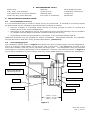
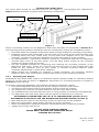
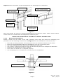
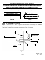
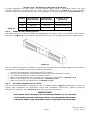
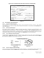
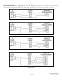
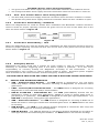
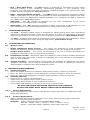
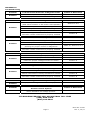
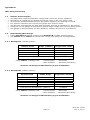
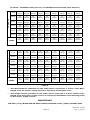
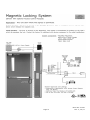
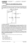
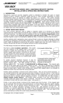
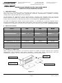
Securitron Magnalock Corp. Tel 800.624.5625 Phoenix, AZ www.securitron.com [email protected] ASSA ABLOY, the global leader in door opening solutions MAGNALOCK MODELS M32, M62 AND M82B INSTALLATION INSTRUCTIONS 1. INTRODUCTION The Securitron Magnalock family represents the state of the art in electromagnetic locking. There are three (3) models with operational electrical characteristics including mounting configuration options addressed in this manual. The BondSTAT “B” Magnalock Series, Bond Sensor, monitors the magnetic field. An internal sensor activates a SPDT dry contact relay connection designed for interface to access control and/or alarm systems for reporting the status of the Magnalock. (Section 5.2.4) The DPS “D” Magnalock Series, Door Position Sensor, is activated by a special magnetic strike armature assembly. The isolated SPDT reed switch, with an internal resettable protection device, is designed for interface to access control and/or alarm system for door status. (Section 5.2.4) 2. SPECIFICATIONS MODEL M32 M62 M82B Holding Force 600 Lbs [272 kg] 1200 Lbs [544 kg] 1800 Lbs [816 kg] Dimensions: Length 8" [203mm] 8" [203mm] 12" [305mm] Height 1.88" [48mm] 3" [76mm] 3" [76mm] Depth 1.6" [41mm] 1.75" [44mm] 1.75" [44mm] Dual Voltage 12/24 Volts DC Current: @ 12 VDC 300mA 250mA 350mA @ 24 VDC 150mA 150mA 200mA Capacitance: @ 12 VDC 6.8 mF 44 mF 44 mF @ 24 VDC 6.8 mF 11 mF 11 mF BondSTAT Rating Voltage: 30 VDC (Maximum) ~ Current: 1 Amp (Maximum) DPS Rating Voltage: 30 VDC (Maximum) ~ Current: 125 mA (Maximum) 3. PRODUCT OVERVIEW Upon unpacking this product, an inventory should be made to ensure that all the required components and hardware have been included. Along with these instructions and the installation template, the lock assembly should include the following items: Sex Bolt Magnalock Strike Plate Hardware Pack Figure 1 © Copyright, 2011, all rights reserved Page 1 PN# 500-10420 Rev. F, 02/11 4. RECOMMENDED TOOLS Power Drill Hammer Wire Strippers/Cutter 1/8”, 3/8”, 1/2” Drill Bits Center Punch Crimp Wire Connectors 1/2” Open end or Crescent Wrench Masking Tape Crimp Tool 3/16” Hex Key (Allen Wrench) Fish Tape or Lead Wire Multimeter 5. INSTALLATION INSTRUCTIONS 5.1 Pre-Installation Survey It is recommended that an initial on sight survey be performed. A method of mounting should be determined and an installation plan should be reviewed as follows: Physical strength of mounting areas should be strong enough to meet or exceed the holding force of the required Magnalock. Placement of the Magnalock wiring and protection from potential damage due to intruders or vandals external attack should be considered during the survey. Accessibility should be considered for prevention of any potential safety hazard. Additional brackets may be needed for proper installation. Specialized brackets are available through Securitron and their many product distributors. (Section 6) 5.2 Out-Swinging Door The installation shown below in Figure 2 illustrates the door swinging away from the Magnalock. This is a common configuration on the secure side of exit doors. The Magnalock mounts to the door frame header near the corner opposite the hinge side. The Magnalock may be mounted horizontally or vertically depending on the installation required. The brackets shown in Figure 2 are to assist installation to door frames that may need modifications to complete the installation. Door Frame & Stop Blind Nuts UHB Bracket Rubber Washers SFP Bracket Magnalock Sex Bolt & Strike Mounting Screw Mounting Screws Door Flat Washers Strike Plate Dress Plugs M32 ~ 2-1/4” M62 ~ 2-1/2” M82 ~ 2-1/2” Figure 2 Page 2 PN# 500-10420 Rev. F, 02/11 Mounting the Strike Plate The strike plate should be mounted prior to the magnet in out-swinging door applications. Figure 3 below illustrates a typical strike mounting configuration. Strike Mounting Screw 2-3 Washers Strike Plate Door Frame & Stop 2X Roll Pins Strike Bushing 2X Roll Pin Bushings Sex Bolt Figure 3 Select a mounting location for the Magnalock and strike assembly as mentioned in Section 5.1. The following general guideline should be used for consideration during the installation review: 5.2.1 Read and follow the template instructions which include drilling and mounting instructions. Installing a strike plate horizontally, the top edge of the strike will be approximately 1/8" [3.2mm] below the door frame stop. If the strike and magnet are to be mounted vertically, increase this clearance between the strike and frame to 3/16" [4.8mm]. An approximated 1” [25.4mm] clearance should be considered between the Magnalock and the edge corner of the door frame. This will allow proper access for the mounting locations for drilling and tool access. Use the template provided for positioning and marking the mounting locations of the Magnalock and strike. Check the external and internal areas of the marked door and frame for any obstacles such as wire chases or internal structural features. Make necessary adjustments to avoid these obstacles. Offset strikes are available for lowering a strike alignment 1/4” [6.0mm] allowing clearance when door construction contains obstructions in the mounting locations. Mounting the Magnet Installations with blade stops require an Aluminum Spacer Bracket (ASB) for clearance without having to cut the stop as shown in Figure 4. Information on mounting brackets is located in Section 6 of this manual. To properly install the Magnalock, the following conditions should be verified: The entire Magnalock mounting area for the magnet must be a flat surface. The frame area selected must be structurally strong enough for support. The magnet face must be mounted parallel to the door face when closed. The installed strike must still allow the door to close properly by clearance and alignment. The Magnalock face and strike plate must be aligned so that they are centered. ALIGNMENT IS IMPORTANT FOR “B” & “D” MAGNALOCKS (Section 5.2.4) ALIGNMENT IS CRITICAL FOR THE MAGNALOCK HOLDING FORCE (Section 2) Mark and drill all holes for the mounting screws as instructed on the template. Make wire connections, apply power and test for proper operation. Mount the Magnalock using the hardware and thread locking compound provided. Tighten the screws until secure. DO NOT OVER-TIGHTEN SCREWS NEVER DRILL MAGNALOCK MOUNTING HOLES – DAMAGE MAY OCCUR – Page 3 PN# 500-10420 Rev. F, 02/11 Figure 4 below illustrates a typical Magnalock out-swinging door installation. Blind Nuts Door Frame & Stop ASB Bracket (Not Included) Magnalock Flat Washers Mounting Screws Mounting Hole Dress Plugs Figure 4 Blind nuts MUST be used for mounting Magnalocks to aluminum and/or hollow metal frames. These items are included with the Magnalock hardware pack. NEVER USE SHEET METAL SCREWS TO MOUNT MAGNALOCKS 5.2.2 Blind Nut Installation Install a blind nut into each of the 3/8” [9.5mm] hole using the blind nut collapsing tool provided. Use the following instructions and Figure 5 for the installation of the blind nuts: Drill 3/8” [9.5mm] diameter mounting holes into the marked locations of the frame. Insert the assembled Blind Nut and Installation Tool into a mounting hole. Use 1/2” [13mm] box-end wrench for holding the Install Nut. Use a 3/16” [5.0mm] Hex Wrench with the Socket Cap Screw to collapse the Blind Nut. Remove the collapsing tool when finished. Check that the blind nut is collapsed properly. The collapsing tool is reusable for several blind nut installations. Blind Nut Install Nut Socket Cap Screw 2X Flat Washers Figure 5 Page 4 PN# 500-10420 Rev. F, 02/11 Lock/Strike Installation for “B” and “D” Magnalocks IMPORTANT! PLEASE READ AND APPLY THIS INFORMATION WHEN ALIGNING/INSTALLING THE LOCK AND STRIKE. THE ALIGNMENT TOLERANCES INDICATED FOR EACH LOCK MODEL ARE CONSIDERED CRITICAL FOR THE PROPER OPERATION OF BOTH THE MAGNETIC BOND SENSING AND DOOR POSITION SENSING SYSTEMS! SENSOR RANGES (PHYSICAL POSITIONING): The BondSTAT “B” and DPS “D” Magnalock “Secure Zone” sensing ranges for each lock model is listed in Table A. Secure Sensor Indication Range (Dimensions from Center) Model "X" (+/-) "Y" (+/-) M32B/D 9/32" 1/8" M62B/D 5/16" 1/8" M82B/D 9/16" 1/8" X (-) 0 (+) Y (+) 0 (-) (+) (-) (-) Table A (+) Figure 6 (The Figure 6 illustration is a visual reference to the sensing ranges outlined in Table A). 5.2.5 In-swinging Door Installation Figure 7 below illustrates a typical in-swinging door mounting configuration. This installation requires the use of a face mount style Magnalock (i.e. M32F, M62F, or M82FB) and a “Z” bracket (Z-32, Z-62, or Z-82) or an adjustable “ZA” bracket (ZA-32/62 or ZA-82) for offsetting the mounting of the strike must be used. Follow the installation instructions provided with the “Z” or “ZA” bracket product to correctly install the Magnalock in this arrangement. THE M62F AND M82FB INCLUDE FIVE (5) MOUNTING HOLES FOR FLEXIBILITY Z-Bracket or “ZA Bracket (Dress cover not shown) Blind Nuts and Mounting Screws Strike Mounting Hardware and T-Nut Door Frame and Stop Strike Plate Sex Bolt Magnalock Bracket Mounting Hardware Door Figure 7 Page 5 PN# 500-10420 Rev. F, 02/11 Single Lock - Double Door Magnalock Mounting A single Magnalock can be used to secure double doors using a split strike plate. The part numbers reduction of holding force for each model is listed below in Table B. Use the template and instructions provided with the split strike package for proper installation. (See Section 7) Table B 5.2.3 Model Offset Strike Part Number Split Strike Part Number Holding Force (per leaf) M32 N/A ASS-32 230 lbs. [104 kg] M62 AOS-62 ASS-62 550 lbs. [250 kg] M82 AOS-82 ASS-82 850 lbs. [385 kg] DM62 Double 62 Magnalock The DM62 consists of two (2) Model 62 Magnalocks arranged in one (1) stainless steel housing as shown in Figure 8. This product individually secures out-swinging double door applications. Figure 8 Use the template diagram installation instructions included with the DM62 Magnalock assembly. The features to consider during the installation procedure: 5.2.4 Position the Magnalock centered between the doors. The mounting diagram measurement and marking placement are critical. The mounting diagram is NOT a scaled template. Refer to the Magnalock out-swinging door mounting procedures in Section: 5.2. Refer to the strike mounting procedures in Section: 5.2.1. Refer to the blind nut instructions in Section: 5.2.3. Mounting Magnalocks for Gates The “G” Series Magnalock is suitable for use on outdoor gates. Figure 9 illustrates a variety of typical gate operations for application types and installation techniques. Special mounting brackets are available. See Section 6.2 for gate bracket information. IMPORTANT THE STRIKE PLATE SHOULD NOT BE WELDED DIRECTLY TO THE GATE THE STRIKE MUST BE MOUNTED USING THE HARDWARE PROVIDED HOLDING FORCE AND ALIGNMENT WILL OTHERWISE BE AFFECTED Page 6 PN# 500-10420 Rev. F, 02/11 GATE STYLE OPERATIONS AND INSTALLATION TECHNIQUES Figure 9 5.3 5.3.1 ELECTRICAL INSTALLATION General Characteristics The Magnalock is a low current load device using specialized internal circuitry. The normal characteristic of an inductive load, such as inductive kick-back, is not present. See Section 2 for more information. 5.3.2 Electrical Standards DC voltage, full-wave rectified, must be provided for proper operation of the Magnalocks. The red wire receives +12VDC or +24VDC, and the black wire, 0 Volts (negative). If the lock is connected with reverse polarity, it will not operate. The M32, M62 and M82B Magnalocks are auto sensing dual voltage locks. The Magnalock circuit design will automatically select the proper operational conditions for the applied voltage. See Section 2 for more information. 5.3.3 Poor Release Characteristics The Magnalock is designed with quick release circuitry. Wiring errors may cause a Magnalock to release slowly. Figure 10 illustrates a parallel installation of a resistive load (correct). Figure 11 illustrates a parallel reverse diode (incorrect). Figure 10 5.3.4 Figure 11 Sensor Ranges (ELECTRICAL) The “B” version monitoring system is also voltage sensitive. The specified voltage ranges must be properly applied. Refer to Section 2 for the recommended operating voltage ranges. Page 7 PN# 500-10420 Rev. F, 02/11 Electrical Wiring The following diagrams, Figures 12, 13, 14 and 15 represent the proper electrical wiring connections required for Magnalock Standard, BondSTAT “B”, DPS “D” and “BD” versions. Figure 12 Figure 13 Figure 14 Figure 15 Page 8 PN# 500-10420 Rev. F, 02/11 5.3.5 5.3.6 BondSTAT Sensor status wiring description The green and white wires supply electrical connection when the lock is ON and secure. The orange and white wires supply electrical connection when the lock OFF or unsecure. DPS – Door Position Sensor status wiring description The blue and yellow wires supply electrical connection when the door condition is closed. The brown and yellow wires supply electrical connection when the door condition is open. Double Door Status Wiring – BondSTAT When two Magnalocks are used for double door installation the BondSTAT contacts should be wired in series for proper reporting. Connect the green wire of one lock to the white wire of the other as shown below in Figure 16. Figure 16 5.3.7 Double Door Status Wiring – DPS When two Magnalocks are used for double door installation the DPS contacts should be wired in series for proper reporting. Connect the blue wire of one lock to the yellow wire of the other as shown below in Figure 17. Figure 17 5.3.8 Emergency Release Magnalocks are often wired into a system for quick release in case of emergency. Manual switching or automatic triggering from a fire alarm system is practical. It is the user's responsibility to correctly hookup the Magnalock according to the instructions. It is recommended to use a switch or relay to perform break of power. Securitron power supplies have terminals for the interconnection of such emergency release switches. THE END USER & INSTALLER ARE LIABLE FOR FIRE & BUILDING CODES COMPLIANCE 6. SPECIALIZED MOUNTING BRACKETS ASB – Aluminum Shim Bracket – The ASB bracket is designed for 1/2” [12.7mm] blade stop and/or weather trim clearance mounting of Magnalocks on aluminum frame glass doors. CWB – Concrete/Wood Header Bracket – The CWB bracket is designed for mounting Magnalocks on concrete filled and/or wood headers. FMK-SL & FMK-SW – FLEX-MOUNT Kit – The FMK (FLEX-MOUNT) bracket kits are designed to install on most gate applications. Adapts to round or square posts from 1” [25.4mm] to 3” [76.2mm]. The FMK-SL is designed for slide gate type applications. The FMK-SW is designed for swing gate type applications. GDB – Glass Door Bracket – The GDB bracket is designed for mounting a Model 32 or Model 62 strike to solid-type framed and unframed glass doors. An AKG adhesive kit used for bonding. HEB Bracket – The HEB is a 90 degree bracket designed to extend the door stop and create a flat surface for mounting the Magnalock. HEB-3G Bracket – The HEB-3G bracket is a 90 degree bracket designed for mounting to solid-type framed and unframed glass headers. An AKG adhesive kit used for bonding. Page 9 PN# 500-10420 Rev. F, 02/11 SFP – Stop Filler Plate – The SFP bracket is designed for extending the door frame mounting surface 1-1/4” [31.8mm]. Thicknesses available in 1/4” [6.4mm], 3/8” [9.5mm], 1/2” [12.7mm] and 5/8” [15.9mm]. Lengths available in 8” [203mm] for M32 or M62 and 12” [305mm] for M82B Magnalocks. UHB – Universal Header Bracket – The UHB bracket is designed to extend the frame width 1” [25.4mm] to 1-1/2” [38.1mm] deeper on steel and aluminum headers not wide enough to mount the Magnalock. Lengths available in 8” [203mm] for M32 or M62 and 12” [305mm] for M82B Magnalocks. Z-Bracket – The “Z” bracket is designed for use with installations of “F” Series Magnalocks for in-swinging doors and gates. ZA-Bracket – The “ZA” bracket is designed to allow a full range of adjustability for use with installations of “F” Series Magnalocks for in-swinging doors and gates. 7. SPECIALIZED STRIKES The AOS – Armature Offset strike is designed for offset drilling doors with mechanical interference hardware present in the door structure. It is also accommodates errors that may have occurred in the field from incorrect mounting placement. (See Section 5.2.5) The ASS – Armature Split strike is designed for single lock/double door installation. There is a reduced holding force when using the split strike. (See Section 5.2.5) 8. SPECIALIZED ACCESSORIES 8.1 Dress Covers Single Magnalock Dress Covers – The covers are designed to meet architectural finishes for matching specified installations. Available in four (4) architectural finishes. Double Dress Covers – The covers are designed to fit over a double door/dual lock installation. Available in two (2) architectural finishes. 8.2 Installation Tool Kit – Securitron offers an installation tool kit which includes special drill bits, a heavy duty drill guide, a blind nut collapsing tool, extra fasteners and hardware. Metric is also available. 8.3 Tamper Proofing – Special tamper proof screws are available for Magnalock and strike armature mounting. The screws are pinned-socket hex head. A special hex wrench is required and is available when purchasing the screws. 9. MAGNALOCK MAINTENANCE 9.1 9.2 Visual Inspection Check the rubber washers for elasticity and proper pivoting. Tighten as required. Check for build-up of debris on the Magnalock and strike armature. Clean as required. Check for rust on the Magnalock and strike plate armature. Clean as required. Cleaning Methods Cleaning once a year is recommended. Clean every six months where minor rusting occurs. Clean every three months if rust conditions are severe. Use a plastic dishwashing scrub pad to aid in the removal of rust. DO NOT USE PETROLEUM BASED PRODUCTS FOR CLEANING DO NOT USE STEEL WOOL BASED SCRUB PAD OR SANDPAPER 9.2.1 Indoor Applications Apply rubbing alcohol onto a clean cloth and thoroughly wipe down the Magnalock and strike plate armature. 9.2.2 Outdoor Applications Apply a silicone based cleaner/lubricant onto a clean cloth and thoroughly wipe down Magnalock and strike plate armature. Example: Super Lube® Aerosol with SYNCOLON® (PTFE) Part No.: 31040 ~ 6oz. / 31110 ~ 11 oz. / 32015 ~ 14 oz. Phone: (631) 567-5300 / Website: www.super-lube.com Page 10 PN# 500-10420 Rev. F, 02/11 APPENDIX A Troubleshooting Problem Lock Does Not Generate a Magnetic Field Points of Reference Check for specified voltage at Magnalock Section 2 Check for specified current draw at Magnalock Section 2 Reduced Holding Force Points of Reference Check DC power source is Full-Wave Rectified (Half-wave Rectifier or AC Power unacceptable) Section 5.3.2 Check for specified voltage at Magnalock Section 2 Check for specified current draw at Magnalock Section 2 Check strike mounting for proper installation Section 5.2.1 and 5.2.5 Check the Magnalock and strike for obstructions and that contact surfaces are properly cleaned Section 8 BondSTAT Does Not Report Secure Points of Reference Check for specified voltage at Magnalock Section 2 Check for specified current draw at Magnalock Section 2 Check strike mounting for proper alignment and pivoting for proper closure to Magnalock Table A / Section 5.2.4 Check the Magnalock and strike for obstructions and that contact surfaces are properly cleaned Section 8 DPS Does Not Report Door Status Points of Reference Check strike mounting for proper alignment Table A / Section 5.2.4 Check for proper door closure Section 8.1 Check for proper voltage/current on switch Section 2 Check resettable protection device Section 1 The Magnalock Does Not Release Points of Reference Make sure no voltage is present at Magnalock Section 2 Make sure the Magnalock is not drawing current Section 2 Check if the strike is sticky and hard to release Section 8 Check the Magnalock and strike for obstructions and that contact surfaces are properly cleaned Section 8 Problem The Magnalock is Dirty or Rusty Points of Reference Solution Improper cleaning – Maintenance Equipment Section 8 Problem Electronic Noise Interference with Access Control System Points of Reference Solution Check for voltage from Magnalock to door frame. There should be no voltage present. Section 2 Solution Problem Solution Problem Solution Problem Solution Problem Solution IF PROBLEMS PERSIST CALL SECURITRON TOLL FREE (800) MAG-LOCK (800) 624-5625 Page 11 PN# 500-10420 Rev. F, 02/11 Appendix B Wire Gauge Factoring 1.1 1.2 Remote Power Supply The Magnalock requires adequate voltage and current for proper operation. Resistance is created by the length and gauge (size) of the wire being used. An accurate estimated distance from the power supply to the opening is crucial. For superior operation the correct size gauge wire must be used. The devices used operate the best with the least amount of resistance on the source. Using the correct gauge wires protects against large voltage and current (load) losses. The gauge is determined by the wire distance, voltage and current of all devices. Determining Wire Gauge Follow Example A (12VDC system) and Example B (24VDC system) below. Use Tables 1 and Table 2 to choose the correct wire gauge for the application. 1.2.1 Example A: (12VDC system) Devices Used Amps (12VDC) Progressive Totals M62 Magnalock DK-26 Access XMS Motion EEB2 Timer 0.250 0.160 0.050 0.025 0.250 0.410 0.460 0.485 0.600A Total Current Rounded Up (Table 1) Using Table 1 (12VDC) Find: - Current Draw - Wire Distance .600 Amps 200 Feet (One-Way) Solution: 18 Gauge is indicated for proper installation 1.2.2 Example B: (24VDC system) Devices Used 24VDC Amps Progressive Totals 0.200 0.025 0.070 0.050 0.020 0.200 0.225 0.295 0.345 0.365 M82 Magnalock TSB Touch Bar DK-11 Access XDT-24 Delay MK Bypass/Reset Total Current Rounded Up (Table 2) Using Table 2 (24VDC) Find: - Current Draw - Wire Distance 0.400A .400 Amps 1000 Feet (One-Way) Solution: 14 Gauge is indicated for proper installation Page 12 PN# 500-10420 Rev. F, 02/11 TO SOLVE: INTERSECT ROW (Current) and INTERSECTING COLUMN (Wire Distance) C U R R E N T 1.00A 20 Gauge 18 Gauge 16 Gauge 14 Gauge 14 Gauge 12 Gauge 10 Gauge 10 Gauge 8 Gauge .800A 22 Gauge 18 Gauge 18 Gauge 16 Gauge 14 Gauge 12 Gauge 10 Gauge 10 Gauge 8 Gauge .600A 22 Gauge 20 Gauge 18 Gauge 18 Gauge 16 Gauge 14 Gauge 14 Gauge 12 Gauge 10 Gauge .400A 22 Gauge 22 Gauge 20 Gauge 18 Gauge 18 Gauge 16 Gauge 14 Gauge 14 Gauge 12 Gauge .300A 24 Gauge 22 Gauge 22 Gauge 20 Gauge 18 Gauge 18 Gauge 16 Gauge 14 Gauge 14 Gauge .200A 24 Gauge 22 Gauge 22 Gauge 22 Gauge 20 Gauge 18 Gauge 18 Gauge 16 Gauge 14 Gauge 50’ [15m] 100’ [30m] 150’ [46m] 200’ [61m] 300’ [91m] 400’ [122m] 500’ [152m] 750’ [229m] 1000’ [305m] 12VDC WIRE DISTANCE Table 1 C U R R E N T 1.0A 22 Gauge 20 Gauge 20 Gauge 18 Gauge 16 Gauge 14 Gauge 14 Gauge 12 Gauge 10 Gauge .800A 22 Gauge 22 Gauge 20 Gauge 18 Gauge 18 Gauge 16 Gauge 14 Gauge 14 Gauge 12 Gauge .600A 24 Gauge 22 Gauge 22 Gauge 20 Gauge 18 Gauge 18 Gauge 16 Gauge 14 Gauge 14 Gauge .400A 24 Gauge 22 Gauge 22 Gauge 22 Gauge 20 Gauge 18 Gauge 18 Gauge 16 Gauge 14 Gauge .300A 24 Gauge 24 Gauge 22 Gauge 22 Gauge 22 Gauge 20 Gauge 20 Gauge 18 Gauge 16 Gauge .200A 24 Gauge 24 Gauge 24 Gauge 22 Gauge 22 Gauge 22 Gauge 20 Gauge 20 Gauge 18 Gauge 50’ [15m] 100’ [30m] 150’ [46m] 200’ [61m] 300’ [91m] 400’ [122m] 500’ [152m] 750’ [229m] 1000’ [305m] 24VDC WIRE DISTANCE Table 2 The Wire Distance indicated on the table above represents a 2-wire “One-Way” length from the power supply source to entryway installation area. The Gauge values specified on the table above represent a 2-wire “Round Trip” length from the power supply source to entryway installation and returning back to the power supply source. IMPORTANT THE 200’ [61m] WIRE RUN IN EACH TABLE FACTORS A 400’ [122m] ROUND TRIP Page 13 PN# 500-10420 Rev. F, 02/11 MAGNACARE LIFETIME REPLACEMENT WARRANTY For warranty information visit www.securitron.com/en/site/securitron/About/MagnaCare-Warranty/ PATENTS BondSTAT Magnetic Bond Sensor - Patent Pending. Page 14 PN# 500-10420 Rev. F, 02/11 Page 15 PN# 500-10420 Rev. F, 02/11 Why choose a genuine Magnalock ? The Securitron Advantages... Electrical Advantages • Low Current Consumption (125mA-350mA) Less Heat for Longer Product Life Smaller Gauge Wire Longer Wire Runs Smaller Power Source Job Cost Savings Double/Triple the Battery Back-up Time for a Secure Facility • Patented “State of the Art” Electronic Circuitry Instant Release Circuit “50 Milliseconds” No Inductive Kickback No Welded Switch Contacts Built-in Noise Suppression No Interference with Sensitive Electronics • Smart Auto Switching Dual Voltage No Jumpers, No Switches, No Errors Sealed and Weatherproof • Securitron Magnetic Locks are 100% Plated & Sealed (excludes M38 & M68 series) Outdoor Installation; Gates, Pool Areas, and Marina Stainless Steel lock casing will not rust Operating Temperature: -40F to +140F [-40C to +60C] • Optional Universal Conduit Fitting (M62 & M82) Secures and Conceals Magnetic Lock cable Increases the Integrity of the Lock Mounting Hardware, Brackets and Tools • Aerospace Collapsing Blind Nuts 1000 lbs tensile strength per blind nut • Grade One Machine Screws 1/4-20 Allows use of “Thread Locker” adhesive • Complete Line of Mounting Hardware for Doors & Frames Herculite, glass, aluminum, metal clad, and wood • Optional Installation Kit A real “Tools of the Trade” kit that reduces installation error and speeds installation time - increasing profits • M38 & M68 Integrated mounting bracket and built-in wire access chamber Fast, easy and fool-proof installation You don’t become the best selling or best warrantied products in the industry without a few firsts. 1ST “E” profile electromagnetic lock 1ST sealed & weatherproof electromagnetic lock 1ST electromagnetic lock that suppresses inductive kickback and electronic noise and provides instant release 1ST electric lock to mount in a standard door strike opening without cutting the frame (UnLatch) 1ST manufacturer in the security industry to offer a “no strings attached” lifetime replacement warranty (MagnaCare) 1ST electromagnetic lock manufacturer to achieve ISO 9001 certification Page 16 PN# 500-10420 Rev. F, 02/11