1
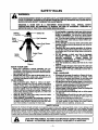
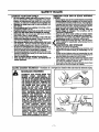
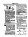
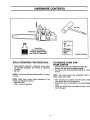
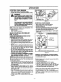
IMPORTANT
MANUAL
Do Not Throw Away
Operator's
Manual
@
Model No.
358.351040
- 14"
Always Wear Eye Protection
CUSTOMER
ASSISTANCE
1-800-235-5878
R# °
2.1 cu. in./34cc 2-CYCLE
GASOLINE CHAIN SAW
WARNING:
READ THE OPERATOR'S
MANUAL AND FOLLOW
ALL WARNINGS AND
SAFETY INSTRUCTIONS.
FAILURE TO DO SO CAN
RESULT iN SERIOUS
iNJURY.
•
•
•
•
•
Assembly
Operation
Customer Responsibilities
Service and Adjustments
Repair Parts
• Table of Contents Inside Back Cover
Sears, Roebuck and Co., Hoffman Estates, IL 60179 U.S.A.
530-083667-1-02/14/95
SAFETY RULES
WARNING:
ALWAYS DISCONNECT SPARK PLUG WIRE AND PLACE WIRE WHERE IT CANNOT CONTACT SPARK
PLUG TO PREVENT ACCIDENTAL STARTING WHEN SE'n'ING UP, TRANSPORTING, ADJUSTING OR
MAKING REPAIRS EXCEPT CARBURETOR ADJUSTMENTS.
BECAUSE A CHAIN SAW IS A HIGH-SPEED WOOD-CUt"rING TOOL, SPECIAL SAFETY
PRECAUTIONS MUST BE OBSERVED TO REDUCE THE RISK OF ACCIDENTS. CARELESS OR
IMPROPER USE OF THIS TOOL CAN CAUSE SERIOUS INJURY.
Headng
Protection _
Do not handle or operate a chain saw when you am
fatigued, III, or upset, or If you have taken alcohol,
drugs, or medication. You must be in good physical
Safety Hat
| _1
•
S_t_!?ng..__
ii_mi_
ous. Ifyou have anyconditionthat might beaggravated
by strenuouswork,check withyour doctor beforeoperating a chain saw.
conditionand
mentallyalert. Chain saw work isstrenuDo not attempt to use your chain saw during bad
weather conditionssuchas strongwind, rain, snow,ice,
_
ores
Carefully plan your sawing operatlon In advance.
Do not startcuttinguntilyou have a clear workarea, secure footing,and, if you are fellingtrees, a plannedre-
Safety
Do not operate a chain saw that Is damaged,
Impropedy adjusted, or not completely and
treat path. assembled.
securely
Always replace the
_..U,....'!i}; afety Chaps
"_N
handgusrd
If It becomes damaged,
broken, or IsImmediately
other wise removed.
Keep the handles dry, clean, and free of oll or fuel
mixture.
• With the engine stopped, hand carry the chain saw
with the muffler away from your body, and the guide
bar and chain to the rear, preferably covered with e
scabbard.
FUEL HANDLING
• EIImlneta all sources of sparks or flames in the areas where fuel Is mixed, poured, or stored. There
shouldbe no smoking,open flames, or work thatcould
cause sparks. Altow engine to cool before refueling.
• Mix and pour fuel In an outdoor area on bare ground;
store fuel in a cool,dry,well ventilatedplace; and usean
approved, marked containerfor all fuel purposes.
• Wipe up ell fuel spills before starting saw.
• Move at least 10 feet (3 meters) from the fueling site
before starting the engine.
• Do not smoke while handling fuel or while operating the saw.
• Turn the engine off end let your saw cool in a noncombustible area, noton dry leaves, straw,paper,etc.
Slowlyremove fuel cap and refuel unit•
• Store the unitand fuel in an area where fuel vaporscannot reach sparks or open flames from water heaters,
eleotdcmotors or switches,fumacas, etc.
•
Figure I
KNOW YOUR SAW
•
Read your operator's manual carefully until you
completely understand and can follow all safety rules,
precautions,and operating instructionsbefore attempting to operate the unit.
Reetrlct the use of your saw to adult users who understand and can follow safety miss, precautions, and
operatingInstructionsfound in this manual.
PLAN AHEAD
•
Wear protective gear. Figure 1. Always use steeltoed safety footwear with non-slip soles; snug-fitting
clothing; heavy-duty, non-slip gloves; eye protection
suchas non-fogging, vented gogglesor faca screen; an
approved safety hard hat; and sound barriers---ear
plugsormufflars to protectyourheadng. Regular users
should have hearing checked regularly as chain saw
noise can damage hearing.
i
when
engineof Isyour
running.
eep the
all parts
body away from the chain
Keep children, bystanders, end anlmal# • minimum
of 30 feet (10 Meters) away from the work ares. Do
not allow other people or animals to be near the chain
sew when starting or operating the chain saw.
I
SAFETY
NOTICE
Exposure to vibrations through prolonged use of gasoline powered hand tools could cause blood vessel or nerve damage in the
f!ngers, hands, and joints of people prone to circulation disorders or abnormal swellings. Prolonged use in cold weather has been
linked to blood vessel damage in otherwise healthy people. If symptoms occur such as numbness pain loss of strength change
in skin color or texture, or loss of feeling in the fingers, hands or joints discontinue the use of this tool and seek medical attention.
An anti-vibration system does not guarantee the avoidance.of these problems. Users who operate power tools on a continual and
regular basis must monitor closely their physical condition and the condition of this unit.
LOOK FOR THIS SYMBOL
IT MEANS- ATI'ENTIONIll
TO POINT OUT IMPORTANT SAFETY PRECAUTIONS.
BECOME ALERTlll YOUR SAFETY IS INVOLVED.
-2-
I
I
I
I
|
J
J
SAFETY RULES
OPERATE YOUR SAW SAFELY
Injury to the operator, helpers, byst._ders or any co.mbination of these persona may resultfrom one-nanoea
o not operate
a chain
with one
hand, Serious
operation.A
chain
saw is saw
intendedfor
two-handed
use.
Operate the chain saw only in well-ventilated out.
door areas.
i
•
i
•
•
•
MAINTAIN
YOUR SAW IN GOOD WORKING
ORDER
Have all chain saw service performed by your Sears
•
specifica|lytrained to do so.
Position ell parta of your body to the left of cut aria
Do
notfrom
operate
• ladder
or In aIstree,
unless
away
the saw
chainfrom
when
the engine
running.
Cut wood only. Do not use your saw ro pry or ShOVe
away limbs, roots, or otherobjects,
Make sure the chain will not make contact with any
object while starting the engine. Never try to startthe
saw when the guide bar Is In a cut or ken.
•
•
Service Center with the exception of the items listedin
the maintenancesectionof this manual. For example, if
impropertools are used to remove or hold the flywheel
when servicing the clutch, structuraldamage to the flywheel can occur and cause the flywheel to burst.
Make certain the chain stops moving when the
throttle trigger is released. For correction, refer to
"CarburetorAdjustments."
Stop the saw If the chain strikes a foreign object.
Inspect unitand repair or replace parts as necessary.
Dleoonnect the spark plugbefore penonnmg any
maintenance except for carburetor adjustments.
Never modifyyour saw In any way. Use only attachments supplied or specifically recommended by the
manufacturer.
and saplings. Slender matedal can catch the chain /_.
AND STORAGE
and
se be
extreme
whipped
caution
toward
when
you or
cutting
pull you
small
off balance,
size brush "TRANSPORTING
Be alert for springbeek when cuttinga limbthat is unStop the unitbefore transporting.
der tension so you will not be struck bythe limb or saw
Allowengine tocool, cover the guide bar and chain, and
when the tension in the wood fibers is released.
secure the unit before storingor transporting in a vehicle.
Do not put pressure on the saw etthe and of • cut.
• Empty fuel tank before storingor transportingthe unit.
Applying pressure can cause you to lose controlwhen
the cut, is completed.
Use up any fuel left in the carburetorby startingthe engine and leffingthe engine run until it stops.
Stop the engine before setting the saw down.
• Store unitandfuel in an area where fuel vapors cannot
Keep fuel end oll caps, screws, end fasteners eeroach sparks or open flames from water heaters, eleccurely tightened.
tric motorsor switches, furnaces, etc.
• Store unitso the chainsannot ascidentally cause injury.
• Store the unitout of the reach of children.
i
GUARD AGAINST
i
KICKBACK - Kickback is a dangerous reaction that can lead to serious injury.
KICKBACK WARNING
Kickback
Path
\
KICKBACK CAN OCCUR WHEN THE
MOVING
CHAIN
CONTACTS
AN
OBJECT AT THE UPPER PORTION OF
THE TIP OF THE GUIDE EAR OR WHEN
THE WOOD CLOSES IN AND PINCHES
THE CHAIN IN THE CUT. CONTACT AT
THE UPPER PORTION OF THE TIP OF
THE GUIDE BAR CAN CAUSE THE
CHAIN TO DIG INTO THE OBJECT,
WHICH STOPS THE CHAIN FOR AN
INSTANT. THE RESULT IS A LIGHTNING
FAST, REVERSE REACTION WHICH
KICKS THE GUIDE BAR UP AND BACK
TOWARD THE OPERATOR.
IF THE
CHAIN IS PINCHED ALONG THE TOP
OF THE GUIDE BAR, THE GUIDE BAR
CAN BE DRIVEN RAPIDLY BACK
TOWARD THE OPERATOR. EITHER OF
THESE REACTIONS CAN CAUSE LOSS
OF SAW CONTROL WHICH CAN
RESULT IN SERIOUS INJURY. DO NOT
RELY ONLY ON THE SAFETY DEVICES
PROVIDED WITH YOUR SAW. AS A
CHAIN SAW USER, YOU MUST TAKE
SPECIAL SAFETY PRECAUTIONS TO
HELP KEEP YOUR cUTrlNG JOBS
FREE FROM ACCIDENT OR INJURY.
Figure 2
Avoid
Obstructions
Clear The
Working Area
Figure 3
-3-
i
SAFETY RULES
Never Reverse
Hand Positions
t
1
q
_m
MAINTAIN CONTROL
Stand To
The Left
Of The Saw
•
Keep a good, firm grip on the saw with both h_a_jd_m
when the engine Is running and don't let go. r'U_n
4. A firmgripcan neutralizekickbackand help yoUm_._
laincontrolot thesaw. Keepthe tingers ofyourlen-_'_"
encirclingend your leftthumbunder the fronthandle_"_
Keep your righthandcompletelyaroundthe rear ha_ 'r
whetheryou are righthanded or left handed. Keep you
loft arm straightwith the elbow locked.
/1
Position your left hand on the front handlebar so-:
Is in a straight line with your right hand on fha.r!..ra,
handlewhen making bucking cuts. Figure4. Nev_
reverse dgnt and left hand positionsfor anytype otcue-
Bbow
\
On
Under Side Of
Handlohar
Figure 4
REDUCE THE CHANCE
OF KICKBACK
• Recognize that kickback can happen. With a basic
understandingof Idckback,you can reducethe element
of surprisewhich contributes to accidents.
• Never lot the moving chain oontect any obJecdat the
tip of the guide bar. Figure 2.
• Keep the workln S area free from obstructions such
as other trees, branches, rocks, fences, stumps, etc.
Rgura 3. Eliminate or avoid a..nyobstructionthat your
chain couldhitwhile you are cumngthrougha particular
log or branch.
• Keep your chain sharp and properly tensioned. A
loose or dull chain can increasethe chance of kickback
to occur. Followmanufacturer's chain sharpening and
maintenance instructions. Check tension at regular intervals with the engine stopped, never with the engine
running. Make sure the bar clamp nuts are securely
tightenedafter tensioningthe chain.
• Begin and continue cutting at full throttle.
If the
chain is moving at a slower speed, there is greater
chance for Idckbackto occur.
Cut one log at s time.
Use extreme caution when re-enlarlng a previous
cut.
• Do not attempt plunge cut=.
• Watch for shlfUng logs or otherforcesthat couldclose
cut the
and pinch
or fall into chain.
• a
Use
Reduced-Kickback
Guide Bar end Low
•
_nd
with your weight evenly balanced on both
feel
• Stand slightly to the left aide of the nw to keep your
body from being in a direct line with the cuu,-u
chain, Figure 4.
Do not overreaoh. You could be drawn or thrown olt
balance and lose controlof the saw.
• Do not cut above shoulder height. It is difficultto
maintain controlof saw above shoulder height.
UNDERSTANDING
Kickback Chain specified for your saw.
KICKBACK SAFETY FEATURES
•
&
•
REACTIVE FORCES
b
Pinch-Kickback and Pull-in occur when the chain.
suddenly stopped by being pinched caught, orin_
centering a foreign object In the wood. This stOPP__
of me onain resultsin a reversal of the chaintome useu
cutwood and causes the saw tomove inthe oppositedirecs
tionof the chain rotation. Either reaction can result m los
of controland possible serious injury.
• Pinch-Kickback
occurs when chain on top of guide bar is sudden_J
stopped.
rapidlydt_vessaw straightback towardoperator.
• PulHn
occurswhen the chainon the bottomofthe guide t_ar
is suddenly stopped,
~ pulls the saw rapidlyfonvaro.
THE FOLLOWING FEATURES ARE INWARNING
CLUDED ON YOUR BAWTO HELP REDUCE
THE HAZARD OF KICKBACK; HOWEVER,
SUCH FEATURES WILL NOT TOTALLY
ELIMINATE THIS DANGEROUS REACTION.
AS A CHAIN SAW USER, DO NOT RELY
ONLY ON SAFETY DEVICES, YOU MUST
FOLLOW ALL SAFETY PRECAUTIONS,
INSTRUCTIONS, AND MAINTENANCE IN
THIS MANUAL TO HELP AVOID KICKBACK
AND OTHER FORCES WHICH CAN RESULT
IN SERIOUS INJURY.
•
*
sampleofchainsaWsbelow3.8_'ubic'inchdisplace_antspa"
siftedin ANSI B175.1-1991.
Handguerd,designedtoreducethechanceofyourle_,h_rd'
contacting
thechainifyourhandslipsoffthefronthsno_e_:_'
Posttlonof front and'rear handlebars,designedwith._.he
tance betweenhandles end "in-line"with eachother', despreadend*in-line"positionofthe handsprovidedbYthtnS_O'
_
signworktogetherto givebaanceand resistance
i_ p°n,."_,.k
lingthe pivotofthe saw backtowardthe operatorif leer,us-occurs,
chain
ANSIBI75.1-1991
-SsfetyrequtrernentsforgssolinepoWSrce.d..
nsaws as set by the American Nation_dStandards In.lute,
de,rd 5175.1-1991.
In -.
Contoured
Def_lc_
Reduced-Kickback Guide Bar, designedwitha small radius
tip whichreduces the size o| the kickbac_ danger zone on the
guidebartip. Figure5. A Reduced-KiekbackGuide Baris one
which hasbeen demonstrated tosignificantlyreducethe humber and seriousnessof kickbackswhen tested in accordance
withANSI B175.1. 1991
Low-Kickback Chain, designed with a contoured depth
gauge and guard linkwhich deflect kickbackforce and allow
wood to graduallydde into the cutter. Figure5. Low-Kicld_ck
Chain is chain which has met kickbackbedormenoa requirements of ANSI B175.1-1991 when tasted on a representative
-4-
Redu¢_l KIckbiCk
Symm_t_d
Guide B4_
Sm•ll
R•allul T_
And AJtoWl
into C,_
SY I11*11etti_
_
Chim
Figure 5
WI_
High
•
PRODUCT SPECIFICATIONS
CONGRATULATIONS on your purchase of a Sears
Craftsman Gasoline Chain Saw. It has been designed, engineered and manufactured to give you the best possible
dependability and performance.
GUIDE BAR: .......................... 14" (36cm)
Should you experience any problems you cannot easily
remedy, please contact your nearest Sears Service Canter/Department. Sears has competent, well trained technicians and the proper tools to service or repair this unit.
CHAIN: .................................. Low Profile 3/8" Pitch
Chrome Cutters
DISPLACEMENT: ................. 2.1 Cubic Inches (34cc)
ENGINE: ................................
FUEL MIX: .............................
OILER: ...................................
IGNITION: .............................
Please read and retain this manual. The instructionswill
enable you to assemble and maintain your unit properly.
Always observe the =SAFETY RULES."
2-cysts Air Cooled
40:1 (3.2oz oil per gallon gas)
Automatic, 6.0 oz Tank
Solid State
(Air gap .010'-.Ot4")
IGNITION TIMING: ................ Non-Adjustable, Fixed
MODEL NUMBER:
SPARK PLUG TYPE: ............ Champ=on CJ-7Y
358.351040 - 14"
SPARK PLUG GAP: ............... 025" (.65ram)
MUFFLER: ............................ Spark Arresting Screen
DATE CODF_JSERIAL NO.
ENGINE RPM: ...................... 12,600 RPM Maximum
,.
DATE OF PURCHASE:
THE MODEL AND SERIAL NUMBER WILL BE FOUND
ON THE PRODUCT.
YOU SHOULD RECORD BOTH SERIAL NUMBER
AND DATE OF PURCHASE AND KEEP IN A SAFE
PLACE FOR FUTURE REFERENCE.
MAINTENANCE
SPECIAL
AGREEMENT
A Sears Maintenance Agreement is available onthis product. Contact your nearest Sears Store for details.
CUSTOMER
If you operate 8 chain sew In • state or locale where such
regulations exist, you ere legally responsible for
malntalnlng the operatlng condition of these parts.
Failure to do so Is • violation of the law. Refer to the
Spark
Arrestor
section
under
=Customer
Responslbnlifes" for maintenance.
RESPONSIBILITIES
•
Read and observe the safety rules.
•
Follow a regular schedule
and using your unit.
•
Follow the instructions under"Customer
Responsibilities and Storage sectionsofthlsOperatorsManual.
in maintaining,
FULL ONEYEAR
NOTICE
Your sewls equipped with etemperature limiting muffler
and spark
arresting
screen
which
meets the
requirements of California Codes 4442 and 4443. All U.S.
forest land and the states of California, idaho, Maine,
Minnesota, New Jersey, Washington, and Oregon require
many intemal combustion engines to be equipped with a
spark arrestor screen by law.
caring for,
MANUFACTURED
UNDER ONE OR 14K)Re OF THE FOLLOWING
OTHER U.S. AND FOREIGN PATENTS PENDING.
WARRANTY
PATENTS: 4,940.0_8.
ON GAS CHAIN SAW
For one year from the date of purchase, when this Craftsman Gas-Powered Chain Saw is maintained, lubricated, and
tuned up according to the owner's manual, Sears will repair, free st charge, any defect in material or workmanship.
This warranty excludes the bar, chain, spark plug, and air filter, which are expendable parts and become worn during normal use.
If this Gas Chain Saw is used for commercial or rental purposes, this warranty applies for 30 days from the date of purchase.
WARRANTY SERVICE IS AVAILABLE BY RETURNING THIS CHAIN SAW TO THE NEAREST SEARS SERVICE CENTER IN THE UNITED STATES.
This warranty gives you specific legal rights, and you may also have other rightswhich vaq/from state to state.
SEARS, ROEBUCK AND CO., D/817WA, HOFFMAN
NOTICE." Refer to the Code of Federal Regulations, Section 1910.266,
safety codes when using a chain saw for producing income.
-5-
ESTATES, IL 60179
ANSI B175.1-1991; ANSI Z133.1; and state
HARDWARE
CONTENTS
1
Chain Saw
FueVOil Mix
(Bar Oil not included)
Purchase Craftsman Bar
and Chain Oil Separately
TOOLS REQUIRED
'm
¸
_j._-=----OperatoFsManual
FOR OPERATION
TO REMOVE CHAIN SAW
FROM CARTON
• Torque Wrench (optional) - Reference torque values
are provided throughout this manual for tightening
hardware.
• Bar Tool
• Remove loose parts bag included with Chain Saw.
• Remove your saw lrom the packing material.
• You may use the opened packing matedai as a work
surface.
NOTE: It is normal to hear the fuel filter rattle in an empty
fuel tank.
NOTE: This model comes fully assembled. Chain is
sharp; unpack with caution.
NOTE: Check chain tension using instructions in the
Service and Adjustment Section:
• Before first use.
• After 1 minute of operation.
• After removing the contents from the carton, check
parts against the Carton Contents list.
• Examine the parts for damage. Do not use damaged
parts.
• Notify your SEARS store immediately ff a part is missing or damaged.
-6-
OPERATION
KNOWYOUR
CHAIN
SAW (See Fig. 6)
READ THIS OPERATOR'S MANUAL AND SAFETY RULES BEFORE OPERATING YOUR CHAIN SAW. Compare the
illustrationswith your unitto familiarize yourselfwiththe locationof the various controlsand adjustments.Save thismanual
for future reference.
FRONT
HANDLE
STARTER
ROPE HANDLE
ON/STOP
SWITCH
CHAIN
PRIMER
BAR OIL
FILL CAP
FUEL MIX
STARTER
HOUSING
FILL CAP
CYLINDERCOVER
FAST IDLE
LOCK
THRO'I-rLE
LOCKOUT
ADJUSTING
SCREW
REAR
HANDLE
THRO'I-I'LE
TRIGGER
CHAIN TRAVEL
DIRECTION
CHOKE
KNOB
BAR CLAMP
_'
CHAIN
CATCHER
GUIDE BAR
NUTS
Figure 6
The ON/STOP SWITCH is usedto stopthe engine.
The STARTERROPE HANDLEisusedforstartingtheengine;.
The CHOKE KNOB activatesthe choke to provideadditional
fuel Io the engine when startinga coldengine,
The THROI-rLE LOCKOUT preventsthe THROTTLETRIGGER frombeing squeezedaccidentally,
The FAST IDLE LOCK allowsforfasterenginespeedsduring
starting.
-7-
The THROI-rLE TRIGGER controls enginespeed.
The GUIDE BARisdesigned to carrythe chain.
The CUTTERS are designed to cutthewood.
The BAR CLAMPNUTS are designedto hold the guide bar
after adjustmentshavebeen completed.
The ADJUSTINGSCREWis designedto tensionthe chainon
the guidebar.
The PRIMER BULBcirculatesfueltothe carburetor.
OPERATION
HOW TO USE YOUR CHAIN SAW
FAST IDLE LOCK
• The fast idle lock allows for faster engine speeds during starting.
• The fast idle lock is engaged by the followingsteps:
- Grasp the rear handleand depress the throttlelockout.
- Squeeze the throttletrigger fully and hold.
- Depress the fast idlelock with your thumb and hold,
- Release your gripon the throttle tdgger and throttle
lock while continuingto hold the fast idle lock.
NOTE: Verify the throttletrigger stays in the advanced
position.
STOPPING
YOUR ENGINE
• Move on/stop switch to the "STOP" position.
• If engine does not stop, pull blue choke knob out fully.
CHAIN OILER (Fig. 7)
• The chain oiler providescontinuous lubrk_.ation
to the
chain and guide bar. Be sure to fill the bar oil tank
when you fill the fuel tank (Capacity = 6.8 fl. oz.).
• Yourchain saw will consume approximatelyone tank
of bar oil for each tank of fuel used.
• Your chain oiler is automatic and requires no adjustmerit.
•
^B,ar
uilFill
Cap
_L t._. Front Handle
u,,-,,,j_ _
Fue Mix Cap
_ _
/
ut
ottle
Trigger
Figure 8
CHOKE (Fig. 9)
Figure 7
THRO'I'FLE CONTROL
• The choke provides additional fuel when starting a
cold engine.
• The choke isactuated by pullingthe bluechoke knob.
• The choke has two positions: partial and full.
GROUP (Fig. 8)
THROTTLE LOCKOUT
• The throttle lockout disables the throttle trigger.
• The throttle lockoutpreventsunintentionalactuationof
the throttle trigger.
THROTrLE TRIGGER
• The throttle trigger allows for variable control of
engine speed.
• The throttle trigger is actuated by the index finger on
your right hand,
Figure 9
-8-
OPERATION
BEFORE STARTING ENGINE:
WARNING:
BE SURE TO READ THE FUEL HANDLING
INFORMATION IN THE SAFETY RULES
SECTION ON PAGE 2 OF THIS MANUAL
BEFORE YOU BEGIN.
IF YOU DO NOT UNDERSTAND THE FUEL
HANDLING SECTION DO NOT ATTEMPT
TO FUEL YOUR UNIT; SEEK HELP FROM
SOMEONE THAT DOES UNDERSTAND THE
FUEL HANDLING SECTION OR CALL THE
CUSTOMER ASSISTANCE HOTLINE AT
1-800-235-5878.
FUEL STABILIZER
Fuel stabilizer is an acceptable alternative in minimizing the
formationoffuelgum depositsduringstorage. Addstabilizer
to gasoline in fuel tank or storagecontainer. Always follow
the fuel mix ratio found on the stabilizer container. Run
engine at least5 minutesafter addingstabilizer to allow the
stabilizerto reach the carburetor.You do not have to drain
the fuel tank for storage if you are using fuel stabilizer.
CRAFTSMAN 40:1 2-cycle engine oil (AIR-COOLED) Is
speciallyblended with fuel stabilizers.If you do not use this
Sears oil, you san add a fuel stabilizer (such as Craftsman
No. 33500) to your fuel tank.
2-CYCLE OIL:
CRAFTSMAN 40:1 2-cycle engine oil (AIR-COOLED) is
specially blended with fuel stabilizers.If you do not use
this Sears oil, you can add a fuel stabilizer (such as
Craftsman No. 33500) to your fuel mix. See Gasoline
and oil mixture"instructionsbelow.
If CRAFTSMAN 40:1 2-cycle engine oil (AIR-COOLED)
is not available, use a good quality40:1 2-cycle engine oil
(AIR-COOLED) that has a recommendedfuel mix ratio
40:1.
IMPORTANTI Do not usa:
GUIDE BAR AND CHAIN OIL
For maximum guide bar and chain life, we recommend
you use CPaftsmanchain saw bar oil. If Craftsman bar oil
is not available, you may use a good grade SAE30 oil
until you are able to obtain Craftsman brand.The oil output is automaticallymetered during operation.Your saw
will use approximately one tank of bar oil for every tank
of fuel mix. Always fill the bar oil tank when you fill
the fuel tank.
• AUTOMOTIVE OIL
• BOAT OILS (NMMA, BIA. etc.)
These oils do not have properadditives for 2.-cycle (AIRCOOPED) engines and can cause engine damage.
GASOUNE
GASOUNE
The two-cycle engine on this productrequiresa fuel mixture
of regularunleadedgasoline and a highquality 40:1 2-cycle
engineoil (AIR-COOLED) for lubricationofthe beadngs and
other moving parts. The correct fuel/oil mixture is40:1 (see
Fuel MixtureChart). Too little oil orthe incorrectoil type will
cause poorperformanceand may cause the engine to overheat and seize.
AND OIL MIXTURE
MIX GASOLINE AND OIL AS FOLLOWS:
• Consult chart for correctquantities.
• Do not mix gasoline and oildirectly in the fuel tank.
FOR ONE GALLON:
Pour 3.2 ounces of high quality, 2-cycle engine oil
(AIR-COOLED) into an empty, approved one gallon
gasoline container.
• Add one gallonof regular
unleededgasoline
to the
galloncontainer,
then securelyreplacethe cap.
Shake thecontainer
momentarily.
• The mixture
isnow readyforuse. Fuelstabilizer
can
be added atthis
timeif
desired;
follow
mixinginstructionson thelabel.
Gasoline and oil must be pmmixed in a clean approved fuel
container. Always use fresh regular unleaded gasoline.
This engine is certified to operate on unleaded gasoline.
IMPORTANT:
Experience indicates that alcohol
blended fuelscalled gasohol (or using ethanol or methanol) can attract moisture, which leads to oil/gas separation and formation of acids during storage. Acidic gas
can damage the fuel system of an engine while in storage. To avoid engine problems, the fuel system should
be emptiedbefore storage for 30 days or longer. Drain
the gas tank, then run the fuel out of the carburetor and.
fuel lines by starting the engine and letting it run until it
stops. Use fresh fuel next season. See STORAGE
instructionsfor additional information. Never use engine
or carburetorcleaner products in the fuel tank or permanent damage may occur.
FUEL MIXTURE CHART
40:1 Fuel:Oil Mix Ratio
1 gallon
3.2
2.5 gallons
8.0
NOTE: Measure fuel correctly. Fuel containers can hold
more than the manufacturer's
specified amount. If too
much gasoline is in the container, the resulting gas-to-oil
ratio will not be correct for proper engine operation.
-9-
OPERATION
STOPPING
YOUR
ENGINE
• Move on/stop switch to the "STOP"position.
• If engine does not stop, pull blue choke knob out fully.
A
WARNING:
STOP y/ll
/1
Choke Po=ltlona."t /
_u__Primer'_ _
ALWAYSWEAR GLOVES; SAFETY FOOTWEAR, SNUG-FR'nNG CLOTHING; AND
EYE, HEARING, AND HEAD PROTECTION
DEVICES WHEN OPERATING A CHAIN
SAW.
___._
A
-- _,_.:--,
I%' '-' I--- OJ
Figure 10
THE CHAIN MUST NOT MOVEWHEN THE
ENGINE RUNS AT IDLE SPEED, REFER
TOTHE "CARBURETOR ADJUSTMENTS"
SECTION FOR CORRECTION.
STARING
AWAR.ENGI"E
•
•
•
•
Move on/stop switch to the "ON"position.
Be sure choke is in the "OFF"position.
Activate fast idle lock.
With saw on ground, grip front handle with left hand
and place right foot through opening in rear handle.
• Pull starter rope handle until engine starts.
• Squeeze and release throttle trigger to return engine
to idle speed.
NOTE: Check chain tension using instructionsin the
Service and Adjustment Section:
• Before firstuse.
• After 1 minute of operation.
BASIC STARTING PROCEDURE
(Fig. 10 & 11)
Right Hand
on
Starter Rope Handle
COLD ENGINE/WARM ENGINE AFTER
RUNNING OUT OF FUEL
• Fuel engine with 40:1 fuel mix.
• Pillbar oil tank with bar oil.Your saw will use approxi*
mately one tank of bar oil for each tank of fuel mix.
• Prime engine by pressing primer bulb six times.
• Turn on ignitionby moving on/stop switch to the "ON"
position.
• Actuate choke by pulling blue choke knob fully out.
Then set the saw on the ground.Gripthe front handle
with your left hand and place your right foot through
the opening in the rear handle.
• Set fast idle by depressing the throttle lock with your
right hand. Then squeeze throttle trigger and hold.
With your thumb, press the fast idle lock down and
hold. Next, release the throttle trigger.
• IFTHROTTLE TRIGGER IS SQUEEZED ACCIDENTALLY DURING STARTING IT WILL BE NECESSARY TO RESETTHE FAST IDLE LOCK.
NOTE: When pullingthe starter rope, do not use the full
extent of the rope as this can cause the rope to break.
Do not let the starter snap back holdthe handle and let
the rope rewind slowly.
-= Pull starter rope handle with your right hand until the
engine attempts to start. Then push the blue choke
knob in to the partial position. Resume pulling handle
until engine starts.
• Above 40 degrees, allow engine to run for approximately 5 seconds, push the choke knob in to the OFF
position,then squeeze and release throttle trigger to
allow engine to idle.
• Below 40 degrees, allow engine to warm up 30 seconds - 1 minute with choke at partial position:Push
choke knobin to the OFF position,then squeeze and
release thmttte trigger to allow engineto idle.
• To stop engine, move on/stop switch to the "STOP"
position.
_"
[" STARTING POSITION ]
/
.,
Left Hand
Right Foot through Openingin Handle
Figure 11
DIFFICULT STARTING/FLOODED
ENGINE
The engine may be flooded with too much fuel if it has
not started after 20 pulls.
Flooded engines can be cleared of excess fuel with the
followingprocedure:
• Activate the fast idle lock.
• Push the choke knob to the "OFF" position
• Verify that on/stop switchis in the "ON" position.
• With saw on ground, grip front handle with left hand
and place right foot throughopening in rear handle.
• Pull starter rope handle untilengine starts.
Starting could require pulling starter rope handle many
times depending on how badly unit is flooded.
If engine still fails to start, refer to "TROUBLE SHOOTING" chart or call the 1-800 number listed on the front
page of this manual.
-10-
OPERATION
- GENERAL
TREE FELLING
F=ellingDirection
WARNING
IF THE TRUNK OR MMBS ARE ROTTING,
THEY CAN FALL UNEXPECTEDLY AND
CAUSE SERIOUS INJURY.
Top
Notch
CUt
AS YOU MAKE YOUR FELUNG CUT, IF
THE SAW APPEARS TO BE BINDING,
THE TREE IS STARTING TO FALL IN THE
WRONG DIRECTION. IMMEDIATELY STOP
THE SAW AND USE A FELLING WEDGE
AND MAUL (HAMMER) TO FORCE THE
FELUNG CUT OPEN. THE WEDGE WILL
HOLD THE FELLING CUT OPEN
ALLOWING YOU TO REMOVE THE SAW.
KEEP EVERYONE AWAY FROM THE
TREE IN ALL DIRECTIONS.
Bottom
Notch _
Cut
/3 I
ree I
dthl
Buttress
Root
/
Figure 12
DETERMINE
•
•
•
•
THE NATURAL FALL DIRECTION
Wind - A tree evenly balanced will fall in the same direction the wind is blowing.
Lean - Use a carpenter's iovel or plumb bob to determine iftree has a natural lean. A leaning tree willtend to
fall in direction of lean.
Shape- A tree willtend to fall towards side that is more
heavily branched.
Other Factors- Contacting or nearby trees, buildings,or
wires can influencethe direction the tree will fall.
CUTI'ING
PROCEDURE
(Fig. 12)
After determiningthe Natural Fall Direction, the tree should
be cut as follows:
IMPORTANT: BEFORE FELLING ATREE, MAKE SURE
YOU HAVE AT LEAST 3 FELLING WEDGES AND A MAUL
(HAMMER) AVAILABLE FOR USE IF NEEDED.
•
Use some means to visually mark the Natural Fall
Direction.
• Mark your notchcut on the Natural Fall Directionside of
the tree approximately18-24 inches above the ground.
• Cut top of the notch first at a 45 degree angle. Saw
through 1/3 of the width of the tree.
• Cut bottom of the notch at a 45 degree angle untilyou
meet the top notch cut. Remove notch of wood.
• On the side of the tree opposite the notchcut, make the
fellingcut. The fellingcut should be 2 inches above the
center point of the notch cut. Before the felling cut is
complete, use wedges to open the cut when necessary
to controlthe direction of the fall. Use wood or plastic
wedges, but never steel or iron, to avoid kickback and
chain damage.
• Cracking sounds,widening of the fellingcut, movement
in the upper branches are aUsignsthat the tree is ready
to fall.
•
If your chain saw binds in the fellingcut, you have three
options:
• If the wrong direction of fall is acceptable, carefully remove the fellingwedge. CUt deeper in the notch side of
the tree until tree starts to fall.
• If the wrengdirectionof fall isnot acceptable,attemptto
use one or more felling wedges to force the tree in the
original direction of fall. Do so by driving the wedges
deeper intothe felling cut.
• Keep everyone away from the tree in all directions and
then seek professional helpl
OPERATION USE/TIPS
•
Clear the work area of debris where you can have secure footing.
• MakesurethereisenoughroomforthstreetofalL Maintain a distanceof 21/2 tree lengthsfromthe nearest person or other objects. Engine noise can drown out a
warning call.
Remove dirt, stones,loose bark, nails,staples, and wire
from the tree where cuts are to be made.
• Plan to standon the uphill side whencuffingon a slope.
• Plan a clear retreat path to the rear and diagonal to the
line of fall.
• Large buttressroots should be removedprior to notch
cut.
• Use a wedge if there is any chance thatthe tree will not
fall in the desired direction.
• We recommendyou cutbranches belowshoulderheight
before fellingtree, (See LImbingand Pruning).
Be alert to signsthat the tree is ready tofall:
• Crackingsounds.
• Widening of the telling cut.
• Movement In the upper branches.
As tree begins to fall, turn off saw, and move quickly
away from directionof fall.
-11-
OPERATION - GENERAL
OPERATION
• Begin cuffingwith the saw chassis against the log.
• Keep engine at full throttle dudngcuttingprocedure.
• Allow the chain to cut for you; exert only light downward pressure. If you force the cut, damage to the
bar, chain, or engine can result.
• Release the throttletdgger as soonas the cut iscompleted, anowin_ the engine to idle. I1you runthe unit
at full throttlewithout cutting,unnecessarywear can
occur to the chain, bar, andengine.
• To avoid losingcontrol when completingthe cut, do
not put pressureon the saw dudngthe end of thecut.
• Stop engine beforesetting unitdownafter operation.
USE/TIPS
•
Cutwood only.Do not cut metal; plastics;masonry;nonwood buildingmaterials;etc.
• Stopthe saw ifthe chainstdkes a foreignobject. Inspect
the saw and mpetr or replace parts as necessary.
• Keep the chain out of dirt and sand. Even a small
amountof dirtwillquicklydull a chain and thus increase
the possibilityof kickback.
To get the "feel"of usingyoursaw before you begin a major
sawingoperation,practicecutting a few small logsusingthe
followingtechnique:
• Accelerate engine to full throttle before enteringcut
by squeezing the throttle tdgger.
• Never cut with engine at partial speeds.
OPERATION SAFETY - GENERAL
GENERALSAFETY
AVOID REACTIVE
PINCH FORCES
Pinch-Kickbackand Pull-In occurwhen the chain issuddenly stopped by being pinched, caught, or by contactinga foreignobjectin the wood. This suddenstoppingof
the chain resultsin a reversal of the chainforce used to
cut wood and causes the saw to move in the opposite
direction of the chain rotation. Pinch-Kickbackdrives
the saw straightback toward the operator. Pult-ln pulls
the saw away from the operator. Eitherreaction can resuit in loss of controland possiblyseriousinjury.
WARNING
IF SAW BECOMES
PINCHED OR HUNG IN A
LOG, DO NOT TRY TO FORCE IT OUT. YOU
CAN LOSE CONTROL OF THE SAW
RESULTING IN INJURY AND/OR DAMAGE
TO THE SAW. STOP THE SAW, DRIVE A
WEDGE OF PLASTIC OR WOOD INTO THE
CUT UNTIL THE SAW CAN BE REMOVED
EASILY. RESTART
THE
SAW AND
CAREFULLY REENTER THE CUT. TO
AVOID KICKBACK AND CHAIN DAMAGE,
DO NOT USE A METAL WEDGE. DO NOT
ATTEMPT TO RESTART YOUR SAW WHEN
IT IS PINCHED OR HUNG IN A LOG.
KICKBACK CAN OCCUR WHEN THE
MOVING CHAIN CONTACTS AN OBJECT
AT THE UPPER PORTION OF THE TIP OF
THE GUIDE BAR OR WHEN THE WOOD
CLOSES IN AND PINCHES THE SAW CHAIN
IN THE CUT. CONTACT AT THE UPPER
PORTION OF THE TIP OF THE GUIDE BAR
CAN CAUSE THE CHAIN TO DIG INTO THE
OBJECT AND STOP THE CHAIN FOR AN
INSTANT. THE RESULT IS A LIGHTNING
FAST, REVERSE REACTION WHICH KICKS
THE GUIDE BAR UP AND BACK TOWARD i
THE OPERATOR. IF THE SAW CHAIN IS!
PINCHED ALONG THE TOP OF THE GUIDE
BAR, THE GUIDE BAR CAN BE DRIVEN
RAPIDLY BACK TOWARD THE OPERATOR.
EITHER OF THESE REACTIONS CAN
CAUSE LOSS OF SAW CONTROL WHICH
CAN RESULT IN SERIOUS INJURY.
-12_
TO AVOID PINCH-KICKBACK:
• Be extremely aware of situationsor obstructionsthat
can cause matedai to pinch the top of or otherwise
stop the chain.
• Do not cut more than one log at a time.
• Do not twistthe saw as the bar iswithdrawnfroman
under-cutwhen bucking.
TO AVOID PULL-IN:
• Always begin cutting with the engine at full throttle
and the saw housing against wood.
• Use wedges made of plastic or wood, (never of
metal) to hold the cut open.
OPERATION SAFETY - GENERAL
FELLING SAFETY
DON'T PUT YOURSELF IN THESE PosmoNs
4--...-
Check the wind--Don't cut down wind
Check the lean--Don't cut on lean side
WARNING
can
and falland
towan:lthe
operator.
Looksnap
for decay
rot. If the
trunk is rotted, it
Check for broken or dead branches which can
fall on you while cutting.
• Be extremely cautious with partially fallen trees
that may be poorly supported. When a tree
doesn't fall completely,set the sew aside and pull
down the tree with a cable winch, block and
taclde,or tractor. To avoidinjuw, do not cut down
a partiallyfallen tree with your saw.
i
- 13-
Check the balance-Don't cut on weighted side
OI ERATION
i
ii
BUCKING
BUCKING USING A SUPPORT (Fig. 15& 16)
Bucldngis cutting a fallen tree to the desired log size.
Anotherlogora stand,suchas a sawhorse,may be useOas
supportswhen bucking.
• Area A - Undercut I/3 of the way through the log.
- Finishwith an overcut.
• Area B - Overcut 1/3 of the way throughthe log.
- Finishwith an undemut.
TYPES OF CUTTING
(Fig. 13)
• Overcutting - begin on the top side of the log with
the bottom of the saw chassis against the log;exert
light pressure downward.
• Undemutting - begin on the under side of the log
with the top of the saw chassis against the log;exert
light pressure upward. Dudng undercutUng,the saw
will tend topush back at you. Be prepared for this
reaction and hold the saw firmly to maintain control.
Undercut
Figure t5
Saw Chassis
Figure 13
BUCKING
ONTHE
GROUND (Fig. 14)
• Overcutwith a 1/3 diameter cut.
• Roll logover and finish with an overcut.
Figure 16
r'll II, 1
, F_.,,,.-.,I ei
Figure 14
OPERATING
USErrlPS
• Cut only one log at a time.
• Cut shetteredwoed vet7 carefully.Sharppieces of woed
could be flung toward the operator.
• Use a sawhorse to cut small logs. Never allowanother
person to hold the log while cuttingand never hold the
log with your leg or foot.
• Do not cut in an area where logs, limbs, and rootsare
tangled such as ina blown downarea. Drag the logsinto
a clear area before cutting by pulling out exposed and
cleared logs first.
• Give spoc=alattention to logs understrainto preventthe
saw from pinching. Make the first cut on the pressure
side to relieve the stress on the log.
OPERATION-SAFETY
BUCKING SAFETY
i
i
I
Stay on uphill side of tree when cutting.
rf-
,
WARNING
DO NOT STAND ON THE
LOG BEING
CUT. ANY PORTION CAN ROLL CAUSING LOSS OF FOOTING AND CONTROL.
NEVER TURN THE SAW UPSIDE DOWN
TO UNDERCUT. THE SAW CANNOT BE
CONTROLLED IN THIS POSITION,
Use Common Sense
-14-
Maintain Secure Footing
OPERATION
PRUNING AND LIMBING
Pruning is removingbranchesfrom a standing tree.
Umblng is removingbranchesfrom a felled tree.
LIMBING (Fig. 17)
•
•
Start at base of the felled tree and work toward the top.
Leave the larger nmbs underneaththe felled tree to support the tree as you work.
Pruning Proeeclure
Rret- Undercut1/3 ofthe waythrough the limbnear
the trunk of the tree.
Second - Finishwith an overcut farther outfrom the
trunk untilthe limb fails.
Third - Cut the remainingstump flush near trunkof
the tree.
Second
Pruning CUt /
i"il
ql First
Figure 18
OPERATING
Figure 17
•
PRUNING
(Fig. 18 )
Small branches- smaller then width of guidebar.
Large branches - larger than width of guidebar.
• Remove small limbswith one cut.
• Remove larger, supportingbranches with the 1/3 - 2/3
cutting techniquesdescribedin the bucking section.
•
•
•
•
•
USE/TIPS
Work slowly, keeping both hands firmly grippedon the
saw. Maintain secure footingand balance.
Keep a clear workarea. Frequentlyclear branchesoutof
the way to avoid trippingover them.
Leave the larger limbsunderneath the felledtree tosupport the tree as you work.
Start at the base of the felled tree and work towardthe
top.
Keep the tree between you and the chain. Cut from the
side of the tree oppositethe branch you are cutting.
Umit pruningto limbsshoulder height or below.
Keep out of the way of the falling limb.
OPERATION-SAFETY
PRUNING AND LIMBING SAFETY
•
Watch out for sprlngpoles. Use extreme caution
when cutting small size limbs. Slender material may
catch the saw chain and be whipped towardyou or pull
you off balance.
•
Be alert for sprlngback. Watch out for branchesthat
are bent or under pressure as you ere cuffingto avoid
being struck by the branchor the saw when the tension
in the wood fibers is released.
WARNING
NEVER CLIMB INTO A TREE
TO LIMB OR
PRUNE UNLESS SPECIFICALLY TRAINED
TO DO SO. DO NOT STAND ON LADDERS,
PLATFORMS, A LOG, OR IN ANY POSITION
WHICH CAN CAUSE YOU TO LOSE YOUR
BALANCE OR CONTROL OF THE SAW.
BE ALERT FOR AND GUARD AGAINST
KICKBACK. DO NOT ALLOW THE MOVING
CHAIN TO CONTACT ANY OTHER
BRANCHES OR OBJECTS AT THE NOSE
OF THE GUIDE BAR WHEN LIMBING OR
PRUNING. ALLOWING SUCH CONTACT
CAN RESULT IN SERIOUS INJURY.
DO NOT CUT IF BRANCHES ARE HIGHER
THAN YOUR SHOULDER. GET A PROFESSIONAL TO DO THE JOB. THIS MAY RESULT IN SERIOUS INJURY.
-15-
CUSTOMER
RESPONSIBILITIES
MAINTENANCE SCHEDULE
Fill in dates as you complete regular service
Before
Use
Alter
Use
Every
5 hrs.
Every
25 hrs.
Yearly
v"
e"
v"
v-
Service Dal
i
Clean Unit and Labels
P"
Check for Damaged or Worn Parts
Check for Loose Fasteners and Parts
_'
_"
_"
Check Chain Sharpness
P,
1!
Guid_ B_r Maintenanc_
P'
Check Vibration Mounts (if so equipped)
_"
Check Clutch DrumSprocket
P"
Clean Air Filter
_"
P"
Replace Spark Plug
Clean/Inspect Spark Arrestor Screen and InspectMuffler
Check Guide Bar Lube
e"
Filter in Fuel Tank
GENERAL RECOMMENDATIONS
The warranty on this unit does not cover items that have
been subjectedto operator abuse or negligence. To receive full value from the warranty, the operatormust maintain unitas instructedin this manual.
Some adjustments will need to be made periodically to
properly maintain your unit.
All adjustmentsin the "Service and Adjustments"section
of this manualshouldbe checked at least once each season.
• Once a year, replace the spark plug,replaceair filterelement and check guide bar and chain for wear. A new
spark plug and a clean/new air filter element assures
properair-fuel mixtureand helpsyour engine run better
and last longer.
• Followthe maintenance schedule in this manual.
P"
BEFORE EACH USE
CHECK FOR DAMAGED/WORN
PARTS
The followingdamaged/worn parts shouldbe referrec
yourSears Service Center.
NOTE: it is normal for a small amount ofoilto appear
der the saw after engine stops. Do not confusethiswi
leakingoil tank.
• On/Stop Switch - ensureon/stop switchfunctionsp
erty by moving the switchto the =Stop" positionan(
surethat engine stops,then restartyourengine and;
tinue.
• Fuel Tank - discontinue use of chain saw if fuel
showssigns of damage or le_#,s.
• Oil Tank - discontinueuse of chain saw ifoil tank
signsof damage or leaks.
• Chain Catcher - replace chain catcher if bent,
damaged in any way.
LUBRICATION
CHART (Fig. 19)
WARNING
DISCONNECT
THE SPARK PLUG BEFORE
PERFORMING
MAINTENANCE
EXCEPT
FOR CARBURETOR ADJUSTMENTS,
INSPECT THE ENTIRE UN_
REPLACE
DAMAGED PARTS. CHECK FOR FUEL
LEAKS AND MAKE SURE ALL FASTENERS
AREINPLACEANDSECURELYFASTENED.
CLEAN UNIT AND LABELS
• Clean the unitusing a damp clothwith a milddetergent.
• Wipe offthe unitwith a clean dry cloth.
Figure 19
(_) Craftsrnanchain saw bar oil.
-16-
CUSTOMER RESPONSIBILITIES
CHECK
FOR LOOSE OR WORN
• Bar Clamp Nuts
• Chain
• Muffler
• Cylinder Shield
• Air Filter
• Clutch Drum/Sprocket
• Throttle TdggeriLockout
• Handle Screws
PARTS
Move on/stop switch to the "STOP" position.
Adjustchain for proper tension. (See Chain Tension).
•" Positionthe file holderlevel (90 °) so that it restson the
top edges of the cutter and depth gauge.
File Holder
GUIDE BAR LUBRICATION
(Fig.20)
For maximum guide bar and chain life, we recommendyou
use Craftsman chain saw bar oil. If Craftsman chain saw
bar oil is not available,you may use a good gradeSAE30 oil
until you are able to obtain Craltsman brand.The oil output
is automaticallymetered during operation.Yoursaw will use
approximatelyone tank of bar oil for every tank of fuel mix.
Always fill the bar oll tank when you fill the fuel tank.
i
I s,oE
Cu tter
er
_.
I
J
"_--_'_t
I FRO VIEW
I
Depth _''-e
"_-*£
Gaug
"_
Guide Bar
& Chairt
Figure 22
Alignthe 30 ° file holder marks parallelwith the bar.
File
30"File
ITop,nEw
I
Cutter
Bar Oil
Fill Cap.
utter
Figure 23
File frominsidetoward outsideofcutter, straightacross
on forward stroke in one direction only. Use 2 or 3
strokes per cutting edge.
Figure 20
SHARPENING CHAIN
(Fig. 21, 22, 23, 24, 25,26, 27 & 28)
Marks
_
WARNING
Figure 24
Keep all cutters the same lengthwhen filing.
File enough to remove an _,damage to cuttingedges
Cutters Same
IMPROPER CHAIN SHARPENING
TECHNIQUES ANDIOR DEPTH GAUGE
MAINTENANCE WILL INCREASE THE
CHANCE OF KICKBACK WHICH CAN
RESULT IN SERIOUS INJURY.
Len_
ALWAYS WEAR GLOVES WHEN
HANDLING THE CHAIN. THE CHAIN CAN
BE SHARP ENOUGH TO CUT YOU EVEN
THOUGH IT IS TOO DULL TO CUT WOOD.
Side Plate
TopPlate
Figure 25
File chain to meet specificationsshown below.
85 °
I FULL
VIEWI
Figure 21
Figure 26
-17-
CUSTOMER
RESPONSIBILITIES
i i
•
•
Place depth gauge tool over each cutter depth gauge.
Rle depth gaugewith a flat fileunUlIt is levelwlththe top
of the depth _auge tool.
"°
•
.
i
• Move on/stop switch to the =STOP"position.
• Remove bar and chain from saw.
• Clean all saw dust and any otherdebris from the guide
bar groove and guide bar oil lubrication hole.
• Lubricateguide bar nose sprocketafter each use.
• Burringof bar roils is a normal processof guide bar rail
wear. Remove these burrs by filing guide bar rail side
edges square with a flat file.
•
Figure 27
Maintain roundedfrontcomer ofdepth gaugewith a flat
file. The very top ofthe depth gauge shouldbe flat with
the front half rounded offwith a flat file.
.0_5" Roundedl
Squared
/
Off
Corned
Figure 30
CLEAN AIR FILTER (Fig. 31)
Figure 28
CHECK GUIDE BAR (Fig. 29 & 30)
A worn guide bar will damage the chain and make cutting
difficult.Check the oondltion of the guide bar e_chtime the
chain is sharpened. Conditionsinc|ude:
• Chain sew cutsto one side or at an angle.
• Chain sew has to be forced throughthe cut.
• Inadequate supplyof oil to the bar and chain.
If replacement is necessary,use only the replacement reduced kickback guide bar specifiedfor your saw. Replace
the guide bar when:
•
•
•
the inside grooveof the guide bar roils is worn.
the guide bar is bent or cracked.
excess heatin
, of the railsis noted.
A dirty air filterdecreases the life and performanceof the
engineand increasesfuel consumptionand harmfulemissions,
Always clean your air filter after 25 tanks of fuel or 5
hours of operation, whichever is less• Clean more Ire.
quentlyin dusty conditions.A used air filter can never be
completelycleaned. It is advisable to replace your air tilter with a new one after every 50 hours of operation, or
annually,whicheveris less•
• Loosen 3 screws on cylinder cover.
• Remove cylindercover.
• Remove air filter.
• Clean the air filter using hot soapy water. Rinse with
clean cool water, and air dry completely prior to reinstalling.
• Lightlyoil air filter prior to installing.Use 2-cycle engine
oilor motor oil (SAE 30). Squeeze excess oil from filter.
This will improve the efficiency of the air filter.
• Reinstallair filter.
• Reinstallcylindercover and 3 screws (15-20 in-lbs).
I
Correct
G roove
Worn Grooves
Cylinder
Cover
Air
Filter
File Edges
Square
Cylinder
Cover
Figure 29
Figure 31
-18-
CUSTOMER RESPONSIBILITIES
REPLACE SPARK PLUG (Fig. 32)
REPLACE
The sparkplug shouldbe replacedeach year to ensurethe
engine startseasier and runsbetter,
Spark Plug gap should be .025"
• Loosen 3 screws on cylindercover.
• Remove cylinder cover.
• Twist,then pull off the spark plug boot.
• Remove spark plug from cylinderand discard.
• Replace with correct spark plug and tighten with 3/4"
socket wrench (10-12 Ib-ff).
• Reinstall spark plug booL
• Reinstall cylinder cover and 3 screws (15-20 in-lb).
The fuelfilterahould be replaced aftereachssason. Never
operate your saw without a fuel tilter. Be careful not to
damage fuel linewhile removing the fuel filter.
FUEL FILTER (Fig. 34, 35 & 36)
Run fuel tank dry of fuel before replacingfuel filter.
Move on/stopswitch to the "STOP" position.
Remove the fuel cap.
Pull out fuel cap retainer using a small pair of pliers.
Bend a piece of wire.
Insert the bent wire intothe fuel tank and hookthe fuel
line. Carefully pull out the fuel line and grab eitherthe
fuel filter or the fuel line with your fingers.
Remove fuel tilter from the tank.
Remove fuel filter from the fuel line.
Either clean the fuel filteror replace it with a new one.
To clean, submerge in warm soapy water for 10 minutes. A very light dish washing liquidis recommended.
Agitate fuel filter until it is clean. Rinse thoroughlyin
warm water and air dry.
Reverse process for installation.
Spark
Plug
Figure 32
INSPECT MUFFLER AND
SPARK ARRESTOR SCREEN (IF INSTALLED)
(Fig. 33)
Asthe unitis used, carbon depositsbuildup on the muffler
and spark arrestor screen (if installed), and must be ramoved to avoid creating a fire hazard or affecting engine
performance.
Required cleaning is even/25 hoursof operation or annually, whichever is less.
Figure 34
Replace the spark arrestor screen if breaks occur.
CLEANING THE SPARK ARRESTOR SCREEN
• Loosen and remove the 2 mufflercover screws.
• Remove the muffler cover (cover snaps into muffler
body).
•
•
•
•
•
Bent Wire -_
FUel Line_'_F-_--'_----_'_
Remove mufflerdiffuserand spark arrestor screen assembly. Notice the orientationof these parts tot reassembly.
Clean the spark arrestor screenwith a wire brush or replace it breaks are found in the screen.
Replace any broken or cracked parts.
Reinstall diffuser and spark arrestor screen assembly
with round holes facing up and towards mufflercover.
Reinstall mufflercover and 2 screws (7-8 ft-lbs).
/_
Figure 35
MUffier Diffuser/
park Arrestor
I Screen
,.,o.,or
Cover
_"f
Fuel Line
Fuel Fi_ilter
Barrel
Filter Neck'
Body
Figure 36
Figure33
-19-
Fuel Filter
SERVICE AND ADJUSTMENTS
CHAIN REPLACEMENT
(Fig. 37, 38, 39 & 40)
I
handling chain. The chain is sharp end
CAUTION: Wear protective gloves when J
can cut you even when it is not moving.
• Move on/stop switch to the "STOP"position.
• Replace the old chainwhen it becomes worn or damaged.
• Use only the Low-Kickbackreplacement chain speci• fled in the "Product Specifications."
• See your Sears Service Center to replace and sharpen individualcutters for matching your chain.
• Loosen and remove the 2 bar clamp nuts.
• Remove bar clamp.
• Remove the old chain.
• Turn adjusting screw by hand counterclockwiseuntil
adjusting pin just touchesthe stop.
• Carefully remove new chain from package. Hold chain
with the drive links as shown in Fig 38.
• Place chain over and behind the clutch.
• Fit bottom of drive links between teeth in sprooket
nose.
• Fit chain drive links intotop of guide bar. Fig 39.
Bar C,_
Figure 40
CHAIN ADJUSTMENT
/
__Y
Bar Clamp Nuts
Dept_ Gauge
Figure 38
• Pull guide bar forward until chain is snug in guide bar
grooves.
• Now, install bar clamp making sure the adjusting pin is
positioned in the lower hole in the guide bar.
Figure 42
To check chain tension:
• Use the screwdriverend of the bar tool to move chain
around the guide bar (Fig 44).
• If chain does not rotate, it is too tight- slightlyloosen
bar clamp nuts and turn adjusting screw 1/4 turn
counterclockwise.Retighten bar clamp nuts•
• If chain is too loose, it will sag below the guide bar
(Fig. 43).
Bar Clamp
\
Adjusting
Pin 1.1
"--_ _ _"
Guide Bar
Figure 41
• Lift up tip of guide bar to check for sag, release tip of
guide bar, then turn adjusting screw 1/4 turn clookwise. Repeat this step until a sag does not exist.
• While littini]tip of guide bar, tighten bar clamp nuts
with the bar tool (provided).Torque 10-15 ft-lbs.
Figure 37
Cutters
(Fig. 41,42, 43 & 44)
• Roll chain around guide bar to ensure kinks do not
exist (rotatesfreely).
• Loosen bar clamp nuts.
• Turn adjustingscrew clockwise until chain just barely
touches the bottomof guide bar.
Guide Bar
//Sag
Figure 39
• Install bar clamp nuts and finger tighten only. Do not
tighten any further at this point,
• Now proceed to the =Chain Adjustment"section.
Figure 43
-20-
SERVICE AND ADJUSTMENTS
• If chain is too loose, refer to "Chain Adjustment."
Loosen bar clamp nuts;then, turn adjustingscrew 114
turn clockwise.Lift up tip of guide bar to check for sag,
Retighten bar clamp nuts.
,Tab
Pulley
Starter
Rope
Handle
Pulley
Figure 44
STARTER
ROPE REPLACEMENT
(Fig. 45, 46, 47, 48 & 49)
i_
ALWAYS WEAR EYE PROTECTION
WARNING:
WHEN SERVICING THE STARTER ROPE.
THE RECOIL SPRING BENEATH THE
" PULLEY IS UNDER TENSION. IF THE
SPRING POPS OUT, SERIOUS INJURY
CAN RESULT.
Replace a broken starter rope or one that is badl
frayed.
NOTE: A recoil spring lies beneath the pulley and is
under tension. If the recoil spring is disturbed, consldereble time and effort will be required to reinstall.
For this reason you may want to let your Sears Service
Center handle this repair. If you try to repair the starter
rope and the recoil spdng popsout, take the unit to your
Sears Service Center.
Pulley Ratchet
Figure 46
• Remove the rope retainer screw and remove any
remaining rope.
• Move away from the fuel tank and melt the end of the
new rope to be installed.Allow the melted end to drop
once.Then, while the rope is still hot, pull the melted
end through a rag to obtain a smooth pointed end.
• Feed rope through starter rope hole in starter housing.
• Guide the rope inside the pulley,then up through the
pulley hole. It may be necessary to push the rope
through with a small Phillipsscrewdriver inserted into
the small hole on the underside of the pulley.
• Wrap rope counterclockwise around the pulley ratchet
and tuck loose end back under rope, leaving a 1" tail
between the retainer rib and screw post.
• Pull rope to tighten.
• install the rope retainer screw and tighten until snug.
Do not over-tighten.
• Rewind all the rope onto the pulley in a clockwise
direction.
• Remove the four fan housing screws and loosen the
two screws on the cylinder cover.
Remove fan housing from the unit.
Fan
Screw
Housing
_
Starter
Rope
Hole
I
\Fan
Housin
,linder
Cover
Screws
_
\
Screw
€_
__
Figure 47
• Twist and push pulley intostarter housing.
Replace and tighten the pulley screw.
j
(Inside Fan Housing)
Figure 45
• To take out rope tension, pull out 10" of rope.While
holdingdown pulley ratchet with thumb, push several
inchesof ropeback intolan housingand catchin notch.
Either hold pulley ratchet with thumb or hold starter
rope handle.Retain rope in the notch and slowlyallow
pulleyto turn counterclockwiseuntiltension is gone.
• Remove the pulley screw in the center of the pulley.
• Gently twistand lift pulley while rotatingcounterclockwise.
Io
-21-
Tab
Figure 48
o
Rope
Retainer
Screw
Screw
SERVICE AND ADJUSTMENTS
• Pullout 10" of rope and catch rope in tab in the pulley.
• Carefully turn the pulleytwo completeturnsclockwise,
keeping the rope against the tab to wind the spring.
• While holding the pulley ratchet, pull the excess rope
throughthe starter rope hole.While holdingtension on
the rope, let rope slowly rewind intothe housing.
--L_
Wind Up Spring
fo_4_r
Rewind
Tension
Figure 49
-22-
• Reinstallfan housing by aligning the fan housing to
the chassis. Then while holding the fan housing
against the chassis, pull the rope handte out until you
feel the fan housing drop into place against the chassis. Slowly,let the rope rewind into starter housing.
• Reinstallthe 4 fan housingscrews and tighten the 2
cylindercover screws.Fig 45.
SERVICE AND ADJUSTMENTS
CARBURETOR
ADJUSTMENTS
Carburetor adjustment Is critical and If done Improperly can permanently damage the engine as well as the
carburetor. Please read all Instructions and consult the Troubleshooting section of this manual before
beginning this process. If the engine does not operate according to these Instructions after repeating the
adjusting steps, do not use the unit. For further 8ssistsnca, please call our customer aselstsnca hotllne at
1-800-235-5878.
If engine does not start, it may be flooded. If in doubt,
read the section on flooded engine in the starting section of this manual prior to beginning any adjustments.
The carburetor has been adjusted at the factory for sea
level conditions.Adjustments may become necessary if
the saw is used at significantlyhigher altitudesor if you
notice any of the following conditions:
• Chain moves when the engine runs at idle speed. See
"Idle Speed Adjustment."
• Saw will not idle. See =Idle Speed Adjustment"and
=Low SpeedMixture Adjustment;
• Engine dies or hesitates when it should accelerate.
See "Acceleration Adjustment."
• Loss of cutting power which is not correctedby air tilter cleaning. See "High Speed Mixture Adjustment."
NOTE: There are three adjustments on the carburetor.
• The Idle Speed Adjustment is marked with the letter
• The two remaining adjustments on the carburetor
are the mixture adjustments. One is marked =L"for
low speed, and the other "H"for high speed.
A
WARNING:
THE CHAIN WILL BE MOVING DURING
MOST OF THIS PROCEDURE. WEAR
YOUR PROTECTIVE EQUIPMENT AND
OBSERVE ALL SAFETY PRECAUTIONS.
CARBURETOR
PRESETS (Fig. 50)
If your engine will not start due to suspected improper
carburetor adjustment, the following presets may be requirad. If used, it is recommended that all steps within
the adjustment procedure be completed in order to
assure a properlyset carburetor. If presets are not needed, proceed to section "Idle Speed Adjustment."
When making adjustments, be careful not to force the
plastic limiter caps beyond the stops or damage will
OCCUr.
Very small adjustments can affect engine performance.
It is important to make slight adjustments and test performance before proceeding. Each adjustment should
be no more than 1/16 of a rum.
• Turn bothof the mixture adjustments countemlockwise untilthey stop.
• Turn the idle speed adjustment clockwise until it
stops. Now turn countemlockwise 4-1/2 turns.
• If engine fails to start after performing carburetor presets, the unit may be flooded. Review the "Difficult
Starting"section of the manual. If problems continue
call the 1-800 number listed on the front cover of this
manual for further assistance.
• Start the engine and operate for three (3) minutes to
warm up.Go to "AdjustingProcedure."
IN "LOW SPEED MIXTURE ADJUSTMENT;' RECHECK IDLE SPEED AFTER
EACH ADJUSTMENT.THE CHAIN MUST
NOT MOVE AT IDLE SPEED,
Figure 50
"23-
SERVICE AND ADJUSTMENTS
ADJUSTING
PROCEDURE
HIGH SPEED MIXTURE ADJUSTMENT"H"
IMPORTANT: DO NOT OPERATE ENGINE AT FULL
THROTTLE FOR PROLONGED PERIODS WHILE
MAKING HIGH SPEED ADJUSTMENTS AS DAMAGE
TO THE ENGINE CAN OCCUR.
IDLE SPEED ADJUSTMENT -'r"
• Allow the warm engine to idle.
• Adjust the Idle Speed until the engine continuesto run
without stalling and without the chain moving.
- Turn clockwise to increase engine speed if engine
stalls or dies.
- Turn counterclockwise to slow engine down and/or
to keep the chain from turning.
No further adjustments are necessary if chain does
not move at idle speed and if performance is satisfactory.
LOW SPEED MIXTURE ADJUSTMENT "L"
• Allow engine to idle.
• Turn the Low Speed Mixture Adjustmentslowlyclockwise untilthe RPM starts to drop.Note the position.
• Turn the Low Speed Mixture Adjustmentslowlycountemlockwise until the RPM speeds up and starts to
drop again. Note the position.
• Set the Low Speed Mixture at the midpoint between
the two positions.
• Make a test cut.
• Based on pedormance ofthe saw whilecutting, adjust
the high speed mixture in 1/16 turn increments as follows:
- Clockwiseif saw smokes or loses power in the cut.
Do not adjust for best power by soundor speed, but
judge by how well the saw performs in the cut.
- Counterclockwiseif the saw has speed while out of
the cut, but dies in the cut or lacks power while cutting.
• Repeat the test cut.
• Continue with 1/16 turn adjustmentsuntilthe saw performanceis acceptable while cutting.
• After completingadjustments,check for acceleration.
ACCELERATION CHECK
• If the engine dies or hesitatesinstead of accelerating,
turn the Low Speed Mixture Adjustment1/16 of a turn
at a time Counterclockwiseuntil you have smooth
acceleration.
• Check the idle speed for stability and no chain movement. Adjustas necessary.
• Recheck for smooth acceleration and stable idle.
Repeat process as necessary for acceptable perforrnance.
-24-
STORAGE
Immediately prepare yourunitfor storage at the end ofthe
season or if it will not be used for 30 days or more.
WARNING
ALLOW THE ENGINE TO COOL, ANn
SECURE THE UNIT BEFORE STORING
OR TRANSPORTING IT IN A VEHICLE.
STORE UNIT AND FUEL IN AN AREA
WHERE FUEL VAPORS CANNOT REACH
SPARKS OR OPEN FLAMES FROM
WATER HEATERS, ELECTRIC MOTORS
OR SWITCHES, FURNACES, ETC.
STORE UNIT WITH ALL GUARDS IN
PLACE. POSITION SO THAT ANY SHARP
OBJECT SUCH AS THE CHAIN CANNOT
ACCIDENTLY
CAUSE
INJURY TO
PASSERS BY.
STORE THE UNIT OUT OF THE REACH
OF CHILDREN.
GAS CHAIN SAW STORAGE
INSTRUCTIONS
Ifyourchain saw is tobe storedfor a period oftime, cleanit
thoroughly prior to storage. Remove any dirt, sawdust,
leaves, oil, grease, etc. Store in a clean dry area.
•
Clean the entire unit.
•
Clean air filter, Refer to "CustomerResponsibilities".
Inspectthe bar clamp area and clean anydirt,sawdust,
grass, or debris that has collected. Inspect the guide
bar and chain; replace a guide bar that is bent,warped,
cracked, broken, or damaged in any other way. Replace a damaged or worn chain.
•
Lightlyoil extamal metal surfaces to prevent rustfrom
forming.
&
handling
chain Is
sharpwhen
end ]
CAUTION:chain.
Wear The
protective
gloves
can cut you even when It Is not moving.
ENGINE
Never use engineor carburetorcleaner productsin the fuel
tank or permanent damage may occurto fuel system Components.
Follow these instructions:
1. Drain the fuel from the unit intoan approved
fuel container.
2. Drain the fuel linesand carburetor by starting
the engine and letting it run untilit stops.
3. Allow the engine to cool before storage.
IMPORTANT:
It is important to prevent gum deposits
from formingin essentialfuel system partssuch as the carburetor, fuel filter, fuel line, or tank during storage. Also,
experience indicates that alcohol blended fuels called
gasohol (or using ethanol or methanol) can attract moisture, which leads to oiVgas separation and formation of
acids during storage which will damage your engine. To
avoid engine problems,the fuel system shouldbe emptied
before storage of 30 days or longer.
Fuel stabilizer is an acceptable alternative in minimizing
the formation of fuel gum deposits during storage. Add
stabilizer to the gasoline in the fuel tank or fuel storage
container. Alwaysfoilewthe mix instructionsfound on stabilizer container. Run engine at least 5 minutes after adding stabilizer to allow stabilizer to reach the carburetor.
Craftsman 40:1 2-cycle engine oil isspeciallyblended with
fuel stabilizers. If you do not use this SEARS oil, you can
add a fuel stabilizer (such as Craftsman #33500) to your
fuel tank.
• Remove spark plug and pour 1 teaspoon of40:1 oil mix
through the spark plug opening. Slowlypullthe starter
rope 8 to 10 times to distribute oll to inner engine surfaces.
• Replace spark plug with a new one of the recommended type and heat range. Refer to "ProductSpecifications".
• Cleaneirfilter. Refer to"Customer Responsibilities*.
• Reinstallall covers and hardware removedfor access;
tighten all screws and fasteners.
• Checkentireunitforleosescrews, nuts, andboits. Replace any damaged, broken, or worn parts.
• Use fresh fuel having the proper gasolineto oil ratio at
the beginning of the next season.
OTHER
• Do not store gasolinefrom one season to another.
• Replace your gasoline can if your can starts to rust.
Rust and/or dirt in your fuel system will cause problems.
•
Apply a coating of oilto the entire surface of the guide
bar and chain; wrap it in heavy paper, cloth, or plastic.
Store your unit in a well ventilated area and covered, if
possible, toprevent dust and dirtaccumulation. Do not
cover with plastic. Plastic cannot breathe and will induce condensationand eventual rustor corrosion.
•
Besure all handles and guardsare in place andare securelyfastened. Replace any damaged parts.
IMPORTANT: Never cover unitwhile engine and exhaust
areas are stillwarm.
-25-
TROUBLE SHOOTING
POINTS
TROUBLE SHOOTING CHART
SYMPTOM
CAUSE
REMEDY
Idle speed set too fast ortoo slow.
Low speed mixture requiresadjustment.
Crankshaft seals worn.
Compressionlow.
None of the above.
1.
2.
3.
4.
5.
6.
7.
1.
2.
3.
4.
5.
Fill tank withcorrect fuel mixture
See "StartingInstructions."
Install new p]ug/sheckignitionsystem.
Clean fuel filter;,inspectfuel line.
See "CarburetorAdjustments."
Move switchto the "START"position.
Contact yourSears Service Center/Dept.
Sea "CarburetorAd ustments."
See "Carburetor Ad ustments."
Contactyour Sears ServiceCenter/Dept.
Contactyour Sears Service Center/Dept.
Contactyour Sears Service Center/Dept.
1.
2.
3.
: 4.
5.
i 6.
Air filterdirty.
Spark plug fouled.
Carburetorrequires adjustment.
Exhaust portsor muffler outlets plugged.
Compressionlow.
None of the above.
1.
2.
3.
4.
5.
6.
Clean or replace air filter.
Clean or replace spark plugand re-gap.
See "Carburetor Adjustments."
Contact yourSears Sewice Center/Dept.
Contact yourSears Service Center/Dept.
Contact your Sears Service Centar/Dept.
Engine
smokes
eXcessively.
1.
2.
3.
4.
5.
Air filter dirty.
Fuel mixture incorrect.
High speed mixturerequires adjustment.
Choke partially on.
Crankcase leak.
1.
2.
3.
4.
5.
Clean or replace air filter.
Refuel with correct fuel mixture.
See "CarburetorAdjustments."
Push Choke knob in.
Contact yourSears Service Center/Dept.
Engine runs hot.
1.
2.
3.
4.
5.
6.
7.
Fuel mixtureincorrect.
High speed mixtureset too low (Lean).
Spark plug incorrect.
Exhaust ports or muffleroutletsplugged.
Carbon build-up on muffleroutletscreen.
Fan housing/cylinderfins dirty.
None of the above.
1.
2.
3.
4.
5.
6.
7.
See "FuelingYour Unit."
See "Carburetor Adjustments."
Replace with correct plug.
Contact yourSeers Service Centsr/Dspt.
Clean spark arrestor screen.
Clean area.
Contactyour Sears Service Center/Dept.
Oil inadequate for
bar and chain
lubdcaUon.
1. Oil tank empty.
2. Oil pump or oil filter clogged.
3. Guide bar oil hole blocked.
1. Fill oiltank.
2. Contactyour Sears Service Center/Dept.
3. Remove bar and clean.
Chain moves at Idle
Speed.
1. Idle speed requires adjustment.
2. Clutch requiresrepair.
1. See "CarburetorAdjustments."
2. Contact your Sears Service Center/Dept.
Chain does not move
when engine is
accelerated.
1.
2.
3.
4.
1.
2.
3.
4.
See "ChainTension."
See =CarburetorAdjustments."
Repair or replace.
Contactyour Sears Service Center/Dept.
Chain clatters
or cuts roughly.
1.
2.
3.
4:
Chain tension incorrect.
Cutters damaged,
Chain worn.
Cuttersdul!, improperlysharpened, Or
depth gauges too high.
5. Sprocketwom.
6. Chain installedbackwards.
1.
2.
3.
4.
See "ChainTension."
Contactyour Sears Service Center/Dept.
Resharpen or replace chain.
Seethe chain Sharpenin_]insti'uctions:
Chain stopswithin
the cut.
1. Chain cutter tops not filedflat.
2. Guide bar burredor bent; rails uneven.
3. Clutch slipping.
1. See the chain sharpeninginstructions.
2. Repair or replace guide bar.
3. Contact your Sears Service Center/Dept.
Chain cuts at an
angle.
1. Cutters damaged on one side.
Enginewill not start
or will run only for
a few seconds after starting.
1.
2.
3.
4.
5.
6.
7.
Fuel tank empty.
Engine flooded.
Spark plug not fidng.
Fuel not reaching carburetor.
Carburetor requiresadjustment.
Stop Switch off.
None of the above.
Enginewill not idle
properly.
1.
2.
3.
4.
5.
Enginewill not
accelerate,lacks
power, or dies
under a load.
Chain tension too tight.
Carburetor requires adjustment.
Guide bar rails pinched.
Clutch slipping.
5. Contactyour Sears Service Center/Dept.
6. Install chain in right direction.
1. Resharpenuntil all cutters have equal
angles and lengths.
2. Chain dull on one side.
2. Resharpen until altcutters have equal
angles and lengths.
3. Guide bar bent or worn.
3. Replace guide bar.
If situationsoccur'which ire not covered in this manual, use care and good judgernenL
Ifyou need assistance, contactyour SEARS Service Center/Department or the
CUSTOMER ASSISTANCE HOTLINE at 1-800-235-5878.
-26-
REPAIR PARTS
61
29
Ref.
I.
2.
3.
4.
5.
6.
7.
8.
Part No.
53O-O47439 Trigger- Throttle
530-015701
Pin
530-037809
Wire - Throttle
530-037803
Cover - Clutch
530-015917
Nut - Bar Mounting
530.037805
Lever - Choke
530-083406 Grommet - Choke Knob
530.037794 Assy - Chassis
10.
530-015701
530.047061
II.
12.
13.
14.
15.
16.
17.
18.
19.
20.
21.
22.
530.01561 I
530-014949
530-038227
530-016095
530-047440
530-015922
530.029850
530.015905
i 530-01590"/
530-015826
530-038593
530-0161 I(
9.
Descdption
(incl. 36.37. 38, 40. 41.
62.63, 64. [29 & 31
from page 281)
Pin
Assy - Clutch Drum
w/Brg
Washer - Thrust
Assy - Clutch
Lever - Kill Switch
Spring - Switch
Lock-out
Clip - Cyl Shield Scow
i Chain Catcher
Screw
Washer - Clutch
Pin - Bar Adjusting
Retainer - Bar Adjustin
Screw - Bar Adjusting
Ref.
l_No.
23.
24.
i 530-038238
530-069698
Hate - Bar Mounting
Kit Oil Pump
(incl. 25-30 & 451
25.
26.
27.
28.
29.
30.
31.
32.
33.
34.
35,
36.
530.038546
530-038543
530-019216
530-037818
530-016097
530-019206
530-038241
530-038373
530-037821
530-030189
530-015775
530-069216
Plug - Dust*
Hunger - Gear Assy
O-Ring*
Body - Oil Pump
Screw - Oil Pump
Block - Seal
Fitting - Elbow
i Pick-Up Tube
i Filter - Oil
37.
38.
530-023877
530-047192
39.
40.
41
42.
43.
44.
45,
530-0i9212
530-016133
530-038278
530-016020
530-016132
530-015905
530-016138
Description
Plug - Oil Filter
Screw
Kit - Fuel Line
(Large Dia.)
Pitting - Fuel Line
Assy - Fuel Cap
w/Retainer (incl. 39)
O-Ring*
I Bolt - Bar
Insert - Chassis
Screw
Bolt
Screw
Pin - Cam
* Included in Gasket Set 530-069608
-27-
ReL
Part No.
Description
46.
47.
48.
49.
50.
51.
52.
53.
54,
55.
56.
57,
58.
530-037820
530-037799
530-038224
530-015940
530-037485
530-069232
530-015892
530-037816
530-027531
530-037817
530-047534
53O-4OO897
530-092322
Worm Gear
Handle - Front
Hand Guard
Screw
Handle - Starter
Kit - Rope
Screw
59.
60.
61.
62.
63.
64.
530-016134
530-015920
530-016080
530-026119
530-038264
530-010846'
65.
66.
530-019143
71-3617
: 71-3629
:71-36365
71-36366
67.
Hsg - Fan
Spring- Recoil
Pulley - Starter
Assy - Flywheel
Washer - Flywheel
Lock Washer Flywheel
Nut - Flywheel
Screw - Pulley
Screw - Rope Anchor
Check Valve
, Plug - Oil Vent
Assy - Oil Cap
(incl. 65}
O-Ring Oil Cap*
Chain14"
Chain - 16"
Bar- 14"
Bar- 16"
REPAIR PARTS
14
30
33
l\
25
_7
35
Ref.
Part No.
Description
Ref.
Part No.
Description
530-069247
29.
17.
530-019210
530-030154
530-0192081
53O-069606
530-069604
Fuel Line Kit
(Small Dia)
Seal - Air Box*
30.
530-047502
Spark Plug
Gasket - Carb Adapter*
Cylinder - Machined
Piston Kit (incl. 22, 23,
Piston & Wrist Pin)
31.
32.
33.
34.
35.
530-014362
530-037652
530-019221
530-038237
530-047207
Ring - Piston
Retainer - Piston Pin
36.
530-037245
Assy - Crankshaft
Assy - Seal & Bearing
Cap - Crankcase
Clip - High Tension Lea_
Screw
37.
38.
39.
40.
4 t.
I 530-036103
530-016132
530-039167
530-015905
530-047442
I.
2,
3.
530-083667
530-037793
530-016101
Operator's Manual
Air Filter - Foam
Nut - Carb Screw
16.
4.
5.
6.
7.
530-037804
530-035343
530-019217
530-015810
Hsg- Air Filter
Carburetor
Gasket - Carb*
Screw
18.
19.
20.
21.
8.
9.
I0.
530-037806
530-016094
530-016102
AdapterScrew
Screw
22.
23.
I I.
12.
13.
14.
15.
530-037798
530-038318
530-038317
530-038340
530-047213
Shield - Cyl
Limiter Cap- High
Limiter Cap - Low
GrommetCarbAdjust
Assy Air Purge
* Included
in Gaskel
Carb
24.
25.
26.
27.
28.
530-029805
530-015697
530-038507
530-047179
530-037935
530-016136
530-016090
Set 530-069608
-28-
Ref.
Part
No.
530-069247
Description
Fuel Line Kit
(Small Dia)
Assy - Wire Hamess
Fuel Filter Assy
Insulator - Heat
Gasket - Muffler*
Back Plate - Muffler
Assy - Muffler (incl.
36, 37 & 38)
Diffuser - Muffler
Screen - Spark Arrest_
Screw
Ignition Module
Screw
Strap - Ground
REPAIR PARTS
SEARS
MODEL
358.351040
Carburetor Kit #530-069703
l_f.
1.
2.
3.
4.
5.
6.
7.
8.
9.
10.
11.
12.
13.
14.
15.
16.
17.
18.
19.
20.
21.
Part No.
DeRrlpao.
530-035296 l Idle Adv. Screw Kit
530-035303 ' Metering Lever
530-035164
Fuel Pump Gasket
530-035166
Fuel Pump Diaphragm
530-035300
Fuel Inlet Screen
530-035293
Needle Spring
(Low Speed)
530-O35383 Low Speed Needle-WT 324
53O-O35384 High Speed Needle-WT 324
530-035295
Needle Spring (High Speed)
530-035162
Welch Plug(5/16)
530-035299
Cup Plug
530-035165
Metering Diaphragm Gasket
530-035014
Metering Diaphragm
53O-O35O28 Metering Lever Pin
530--035016 Metering Lever Pin Screw
530-035301
Inlet Needle Valve
530-038318
LitfflterCap - High
530-038317
Limiter Cap - Low
530-035399
Carburetor Repair Kit
(Incl. 1-20)
53O-O35302I Metedng Lever Spring
530-O69703 Carburetor Kit
(Incl. Carb., 17 & 18)
Not Shown
530-031157
530-031161
-29-
UmiterCap Removal
Tool
UmiterCap Insertion
Tool
NOTES
-30-
TABLE OF CONTENTS
Safety Rules....................................................................
Product Specification......................................................
Warranty ..........................................................................
Operation ........................................................................
Customer Responsibilities.............................................
Service and Adjustments..............................................
2
5
5
7
16
20
Storage..........................................................................
Trouble Shooting...........................................................
Repair Parts.....................................
Accessories............................................................
Repair Parts Ordering/Service ......................................
25
26
27
31
32
INDEX
A
Accessories................................................................... 31
Air Filter......................................................................... 18
B
Bar and Chain Oil............................................................ 9
Bucking ......................................................................... 14
C
Carburetor Adjustments................................................ 23
Chain Oiler......_............................................................... 8
Chain Sharpening......................................................... 17
Chain Adjustment................................... ....................... 20
Customer Responsibilities............................................. 16
Spark Plug.............................................................. 19
E
Engine
Fuel/Oil ..................................................................... 9
Spark Plug .............................................................. 19
Starting ................................................................... 10
Storage ................................................................... 25
F
Fuel Filter ...................................................................... 19
Fueling ............................................................................ 9
G
Guide Bar and Chain Oil ................................................. 9
Guide Bar Lubrication................................................... 17
H
Hardware Contents ......................................................... 6
How To Use YourChain Saw .......................................... 8
K
KnowYour Chain Saw ..................................................... 7
L
Limbing .......................................................................... 15
M
Maintenance Schedule ................................................. 16
Model Number................................................................. 5
Muffler ........................................................................... 19
O
Operation ........................................................................ 7
Ordering Repair Parts ................................................... 32
P
Pruning.......................................................................... 15
R
Repair Parts.................................................................. 27
S
Service and Adjustments.............................................. 20
Spark ArrestorScreen .................................................. 19
Specifications.................................................................. 5
Starter Rope.................................................................. 21
Starting.......................................................................... 10
Storage.......................................................................... 25
T
Tree Felling.................................................................... 11
Trouble Shooting ........................................................... 26
Throttle ControlGroup .................................................... 8
W
Warranty.......................................................................... 5
ACCESSORIES
These accessoriesand attachments were available when the unit was originallypurchased. They are also available at
most Sears retailoutletsand senricecenters. Most Sears storescan orderthese itemsfor you when you providethe model
number of your unit.
PERFORMANCE
Air Filter
Spark Plug
Engine
Bar OII
on
_2-cycle
3.2oz.
8oz.
16oz.
lqt.
I
1gal.
MAINTAINENCE
Carrying
Case
Gloves
Guide Bar
Safety
Goggles
-3t-
Chain
Hearing
Protection
Chain
Sharpener
f
CRRFTSMRN
Operator's
Manual
2.1 cu. in./34cc 2-CYCLE
GASOLINE CHAIN SAW
Model No.
358.351040
- 14"
IF YOU NEED REPAIR
SERVICE OR PARTS:
REPAIR SERVICE
1-800-4-REPAIR
(1-800-473-7247)
Each Gasoline Chain Saw has its own model number. The model
number for your unit will be found on a decal attached to the unit.
All parts listedherein may be ordered through Sears, Roebuck and
Co. Service Centers and most Retail Stores.
WHEN ORDERING REPAIR PARTS, ALWAYS GIVE THE FOLLOWING INFORMATION
• PRODUCT - "GASOLINE CHAIN SAW"
• MODEL NUMBER - 358.351040 - 14"
ORDERING PARTS
1-800-FON-PART
(1-800-366-7278)
• PART NUMBER
• PART DESCRIPTION
CUSTOMER
ASSISTANCE
1-800-235-5878
Your Sears merchandise has added value when you considerthat
Sears has service units nationwide staffed with Seam trained technicians.., professional technicians specifically trained on Sears
products, having the parts, tools and the equipment to insure that
we meet our pledge to you, we service what we sell.
Sears, Roebuck and Co., Hoffman Estates, IL 60179 USA