1
Simrad SP90
Electrical continuity must be ensured along the entire length of
all cable coverings, particularly at joints and splices. In no case
should the shielding of cables be used as the only means of
grounding cables or units.
Metallic casings, pipes and conduits must be grounded, and
when fitted with joints these must be mechanically and
electrically grounded locally.
Cable connections
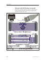
All cable connections are shown on the applicable cable plan
and interconnection diagrams.
Where the cable plan shows cable connections outside an
equipment box outline, the connections are to be made to a plug
or socket which matches the plug or socket on that particular
item of equipment.
Where two cables are connected in series via a junction box or
terminal block, the screens of both cables must be connected
together but not grounded.
Cable terminations
Care must be taken to ensure that the correct terminations are
used for all cable conductors, especially those that are to be
connected to terminal blocks. In this case, crimped
sleeve-terminations must be fitted to prevent the conductor core
from fraying and making a bad connection with the terminal
block. It is also of the utmost importance that where crimped
terminations are used, the correct size of crimp and crimping
tool are used. In addition, each cable conductor must have a
minimum of 15 cm slack (service loop) left before its
termination is fitted.
Cable identification
Cable identification codes corresponding to the cable number
shown in the cable plan must be attached to each of the external
cables. These identification codes should be positioned on the
cable in such a way that they are readily visible after all panels
have been fitted. In addition, each cable conductor should be
marked with the terminal board number or socket to which it is
connected.
86
851-164510 / Rev.E