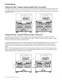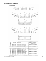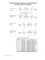
1
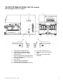
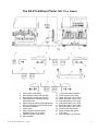
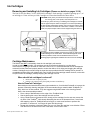
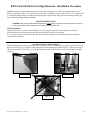
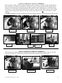
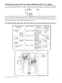
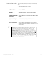
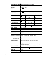
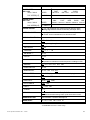
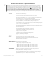
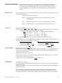
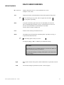
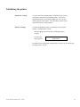
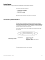
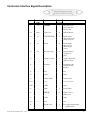
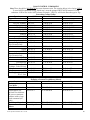
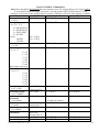
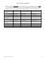
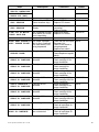
INSTRUCTION MANUAL
FOR
RENA MODEL
DA615
DIRECT ADDRESS INKJET PRINTER
Part #: M-3029
Revision Date 3/00
Rena Systems Inc.
136 Green Tree Road STE 140
Oaks, PA 19456-1069
610-650-9170
610-650-9171 (FAX)
E-Mail: [email protected]
Web Site:www.renausa.com
DA615 Operations Manual 3 Rev. 3-23-00
RENA Systems, Inc.
136 Green Tree Rd Ste 140
PO Box 1069
Oaks, PA 19456-1069
Telephone: 610/650-9170
Fax: 610/650-9171
E-Mail: [email protected]
Web Site: http://www.renausa.com
Every effort has been made to assure the accuracy of this manual.
RENA Systems shall not be held liable for any errors contained herein or for any consequential or incidental damages
incurred as a result of acting on information contained in this manual.
Technical specifications may change due to design advances.
The data stated are nominal values only.
DA615 Operations Manual 3 Rev. 3/23/00
2
INDEX
DA615 Instruction Manual
PAGE # DESCRIPTION
4
5
6
7
8
9 – 13
12
14
14 – 16
17 – 18
19 – 22
23 – 24
25 – 34
34
35
36 – 38
39
40
41 – 42
43
44 – 47
48 – 52
53 – 54
Identifying Items and Accessories (S/N 130 or lower)
Identifying Items and Accessories (S/N 131 or higher)
Connecting the Printer (AC Power, Data Cable)
Control Panel Functions (Key Designations)
Display Characters/Descriptions
Printer Setup Information
(Transport Height, Transport Pressure, … Adjustments)
Modifying the DA615 (S/N 131 or Higher) for Left to Right Paper Transport
Ink Cartridge Maintenance/Cleaning
Ink Cartridges (Which Cartridge to use; How to Replace, Remove, Install)
Address Positioning
How to Enter and Use the Printer’s Programming Modes.
Menu Table (Program Modes)
Menu Feature / Option Definitions
Head Counter Reset Information
Printer Resets (Initializing the printer)
Data Communication (Centronics Port Description, RS-232 Port Description)
Font Control Command Codes
Bar-coding & Custom Test Macro Control Command Codes
Miscellaneous Control Command Codes
How to recall and print a “downloaded” font via escape sequences
Error Messages and Hints
Accessories (Optional)
Technical Data (Specifications, Speeds, Max Paper Thickness)
DA615 Operations Manual 3 Rev. 3/23/00
3
The DA 615 Address Printer (S/N 130 or lower)
(See next page for S/N 131 or higher.)
1
2
3
4
5
6
7
8
9
10
Control panel with display
Head position locking knob (left)
Head position locking knob (right)
Paper thickness / transport pressure
adjustment knob
Paper transport system height adjustment
knob (for matching height of feeding unit)
AC power receptacle
Power switch
Paper transport direction switch
Parallel interface (Centronics)
Serial interface (Not Enabled at this time)
DA615 Operations Manual 3 Rev. 3/23/00
11
12
13
14
Inkjet cartridges (4)(C6131A)
Upper paper transport rollers (8)
Paper side guide (left) (large and
small)
Paper side guide (right) (large
and small)
4
The DA 615 Address Printer (S/N 131 or higher)
(See previous page for S/N 130 or lower.)
1
2
3
4
Control panel with display
Head position locking knob (H4-H3)
Head position locking knob (H2-H1)
Paper thickness / transport pressure
adjustment knob
5 Paper transport system height adjustment
knob (for matching height of feeding unit)
6 AC power receptacle
7 Power switch
8 Paper transport direction switch
(Disabled in S/N 141 or higher)
9 Parallel interface (Centronics)
10 Serial interface
DA615 Operations Manual 3 Rev. 3/23/00
11
12
13
14
15
16
17
18
19
20
(11a) AF500 feeder Interface
Center support (615.0.098)
Paper side guide 1(615.1.076)
Paper side guide 2 (615.1.077)
Wide side guide 3 (615.1.078)
Wide side guide 4 (615.1.079)
Short side guide 5 (615.1.080)
Short side guide 6 (615.1.081)
Thumb screw (K2913.029)
Paper transport aid (option)
(615.2.051)
21 Inkjet cartridges (4) (C6131a)
5
Connecting the printer
Power line
NOTE!
The DA615 is a protection class 1 device.
The printer may be operated only from power sources equipped with
protective grounded terminals!
Plug the power line into the socket on the right of the printer (6).
Switching the printer on
Switch the printer on with the power switch (7).
Interface
Connection
AF500 Feeder Interface
Valid with DA615 S/N 131 or higher
and AF500 S/N 400 or higher.
DA615 Operations Manual 3 Rev. 3/23/00
Plug the parallel interface cable into the interface connection (9)
and connect plug its other end into your computer. The DA615 also
has a 9 pin, RS-232C serial interface connection (10).
The feeder interface cable (11b), supplied with the Rena AF500
(S/N 400 or higher), connects to the DA615’s (S/N 131 or higher)
feeder interface socket (11a). The stop/start function of the AF500
feeder is now controlled by the DA615.
NOTE: The feeding speed of the AF500 must be manually adjusted,
so that it is slightly slower than the transport speed of the DA615.
6
Control panel
In off-line
mode
Head
recovery
Reset
address
counter
In
programming
In programming mode, menu settings are made on the printer (see
overview table at the end of the operating instructions). In this mode, the
upper line of the key lettering applies (end, next, prev, enter)
mode
In
combination
with the
power switch
DA615 Operations Manual 3 Rev. 3/23/00
Key combination
Power on + Prog
Power on + Start
Meaning
Reset to works default
HexDump
7
What does the display show?
Additional Operation mode items displayed
???
=
Addresses (Data) are still left in buffer. You must feed more envelopes to print remaining data.
NoD
=
Data was received, but no end of address marker (Form Feed (OC Hex)) was received.
+
DA615 Operations Manual 3 Rev. 3/23/00
CARTRIDGE PURGE FEATURE:
The printer’s “Head Recovery” feature can be used to help un-clog print
nozzles. Pressing the START and Back Space (Repeat Address(es))
keys together will cause the printer to do a “Head Recovery”. All nozzles
are then fired onto a mail piece. It is recommended that this feature be
used after cleaning ink cartridges and anytime after the printer is
paused, just before putting the printer on-line.
8
Printer Setup
Setting the Paper Transport System Height (Table Top Height)
The Height of the DA615’s table top, can easily be raised or lowered using the Paper Transport System Height Adjustment Knob
(5) to match the input of the printer to the output height of the feeder or conveyor. Turning the knob (5) counter-clockwise will
lower the height of the paper transport table. Turning the knob (5) clock-wise will raise the paper transport table. The range on this
adjustment is 10mm.
Setting the Paper Transport Pressure (Paper Thickness)
The paper transport pressure can be increased or decreased by turning the Paper Thickness/Transport
Pressure Adjustment Knob (4). Turning the knob (4) counter-clockwise will increase the pressure. Turning
the knob (4) clockwise will decrease the pressure.
To adjust the transport pressure, start with the pressure rollers raised high enough so that you can slide your
mail piece between all four upper pressure rollers under either H1&2 or H3&4. Slowly lower the upper
pressure rollers, increasing the pressure until the mail piece becomes difficult to pull out from between the
rollers.
NOTE: Too little transport pressure will cause slipping of the mail piece, which will distort images, and or
change print positions. Too much pressure can cause jamming, and or the mail piece may contact the guides
beneath the print heads and the image may be smudged.
DA615 Operations Manual 3 Rev. 3/23/00
9
Paper Transport System Height Adjustment Scale
(Starting with DA615 S/N 131 or higher.)
Paper Transport Pressure Adjustment Scale
(Starting with DA615 S/N 131 or higher.)
DA615 Operations Manual 3 Rev. 3/23/00
10
Selecting the Paper Transport Direction (Valid for DA615 S/N 130 or Lower!)
For DA615 S/N 131 or higher, please see the following page!
Using the Paper Transport Direction Switch (8), the DA615 can be set to feed material from left to right, or from right
to left (D), as shown below. This switch (8) is only recognised by the DA615 during power up.
NOTE: There is also a menu selection “Transp. Direct.” which can be used to change the paper feed direction,
after the printer has been powered on. This setting will be over-ridden, once the DA615 is powered off and on
again. To make your paper feed direction choice permanent; make sure you set the switch (8) correctly.
+
Feed Direction
DA615 Operations Manual 3 Rev. 3/23/00
The Paper Transport Direction Switch (8) is only recognized during
initial power up of the DA615. If this switch (8) is changed after the
printer is powered on, the printer will not respond to the change, until
the printer is powered off and on again.
Feed Direction
11
Modifying the DA615 (S/N 131 or Higher) for Left to Right Paper Transport
Unless otherwise noted, all DA615’s S/N 131 or higher are set-up to feed from right to left only!
Due to the new transport pressure roller arrangement, the Paper Transport Switch (8) has been
disabled (disconnected from the Main PCB) in DA615 S/N 141 or higher.
It is recommended that a qualified Rena Service Person, make the following adjustments.
Please contact your local Rena Dealer if left to right paper transport is necessary!
•
Replace the Hold Down Sets
If left to right feeding is needed, then the transport pressure roller assemblies (hold down sets) (1-4)
must be replaced with the optional hold down sets (7-10). Please be sure to order the correct
assemblies. These assemblies are different for machines with pinwheels located under the print head
units. (S/N 141 or higher need assembly #11 & 12 for left to right feed.). See the chapter entitled
“Accessories” for details.
•
Enable Left to Right Paper Transport
It will also be necessary to disconnect the Paper Transport Switch (8) form position JP2, or remove
the jumper at position JP2, on the Main PCB to enable left to right transport only!
After making these adjustments, the DA615 will be capable of feeding from left to right only!
Def. = Right to Left
Opp. = Left to Right
DA615 Operations Manual 3 Rev. 3/23/00
12
Installing the Material Side Guides
Select the material side guides that best suit the feeding of your material. Material side guides (13) are secured to the
“entrance end” of the DA615, using the thumbscrews (19) provided, as shown below.
The chapter entitled “Accessories” gives an overview of the optional guide brackets, which can be ordered to suit your
individual material sizes, if those supplied with the printer are not sufficient.
NOTE: The term “entrance end” is dependent on the selection of the paper feed direction.
Center support guides (12) may also be installed, as required, between the material side guides.
DA615 Operations Manual 3 Rev. 3/23/00
13
Ink Cartridges
Removing and Installing Ink Cartridges (Please see details on pages 15-16)
The DA615 uses four Rena C 6131A (HP51645A) cartridges. Each cartridge is capable of printing up to ½ of
an inch high, or 3 lines at 6 lines per inch. Cartridges are removed and installed as shown below.
+
+
CAUTION: Never place your hands into the print area, or touch any of
the moving parts, of the printer, when the printer is on.
To avoid injury when removing or installing print cartridges, first make
sure the paper transport rollers are stopped. To avoid the possibility of
the feed system automatically starting, due to the printer receiving data
to print, the DA615 should be set to the off-line condition. In the off line
mode, the paper transport rollers can be stopped using the PAP key.
Ink cartridges must be installed and removed correctly in order to avoid
possible damage to the head cables. Head cable damage will cause
dot drive problems. Please see the detailed instructions on the
following pages regarding the installation and removal of ink cartridges.
Cartridge Maintenance
The DA615 does NOT automatically clean the ink cartridge’s print nozzles.
In order to maintain print quality, ink cartridges must be removed and cleaned on a routine basis.
If the DA615 is not going to be used for more than a few hours, it is recommended that the ink cartridges be
removed from the printer and properly stored to reduce the chance of ink drying and clogging the cartridge
nozzles. Cartridges may be sealed using the clear blue tape provided with each cartridge and or placed in a
re-sealable container along with a damp cloth. Don’t let the nose of the cartridge contact the cloth, or the cloth
will pull ink from the cartridge, possibly emptying the cartridge of all ink.
When should ink cartridges be cleaned?
•
•
Before the start of a print job (run).
During a run, whenever the print quality becomes unsatisfactory.
How to Clean Ink Cartridges
New techniques and materials have been recommended to us, from Hewlett Packard®, to improve the
process of manually cleaning cartridges. HP® recommends using a material called TexWipe® (TX
304), which is a lint free material. They also suggest using distilled water in the cleaning process.
Here is the recommended procedure:
• Place a drop of distilled water on the edge of the TexWipe® cloth.
• Start by placing the nose of the cartridge onto this wet area.
• Using a small amount of downward force, slowly pull the cartridge from the wet area, across the
dry area of the TexWipe®, while slowly decreasing the amount of downward force. I have found
that wrapping a piece of TexWipe® around a finger, to create a soft surface to perform this
procedure on, works well. Your finger will get a little dirty though.
• Repeat this procedure a few times. Make sure you only clean the cartridge in one direction. Either
from the front of the head to the back of the head, or from back to front.
DA615 Operations Manual 3 Rev. 3/23/00
14
RENA DA615 InkJet Cartridge Removal / Installation Procedure
NOTE: The pictures of the printhead carriage, shown in this procedure, are of a DA610’s printhead carriage. The
DA615’s printhead carriage is very similar to that of a DA610. In addition, the new DA615s (S/N 131 or higher) have
a re-designed printhead carriage installed, which among other improvements, helps protect the cartridge-securing clip
from being bent during cartridge installation.
PRINTER PREPARATION
CAUTION: Until you have followed the steps below, never place your hands into the print area or touch any
of the moving parts of the printer while the printer’s power switch is ON.
DA615 Preparation
Make sure the DA615 is off-line. The START key is used to toggle between the on-line and off-line condition.
If the feed rollers are still turning, press the PAP key to stop the feed rollers from turning.
It is now safe to remove or install cartridges. Please follow the procedure for removing and installing cartridges as
outlined in this document.
AVOIDING HEAD CABLE DAMAGE
When inserting and removing ink cartridges, make sure the nose of the cartridge (Figure 1) does not make contact with
the Head Cable (Figure 2). The nose of the cartridge has a small protrusion of plastic (Figure 1). If this plastic edge is
allowed to contact the Head Cable, it will damage the Head Cable. Do NOT install or remove cartridges at an angle
(Figure 3).
Figure 1
Figure 2
Figure 3
DA615 Operations Manual 3 Rev. 3/23/00
15
HOW TO CORRECTLY INSTALL CARTRIDGES
When inserting a cartridge, keep the cartridge as upright as possible (Figure 4). Push the cartridge straight back into
the Printhead Carriage, until it just touches the Cartridge Securing Clip. Then push down on the cartridge, until it
bottoms out. While pressing the cartridge down, push back at the base of the cartridge (Figure 5) until the cartridge’s
Foot (Figure 7) is positioned completely behind the Bar (Figure 8). Now press back lightly on the top of the cartridge
(Figure 6) until it snaps securely under the Cartridge Securing Clip (Figure 9). Do not use a lot of force to seat the
cartridge.
CAUTION: Pushing the top of the cartridge back before the cartridge is properly seated will damage the Securing Clip
Figure 4
Figure 7
Figure 5
Figure 8
Figure 6
Bottom View
Figure 9
HOW TO CORRECTLY REMOVE CARTRIDGES
When removing a cartridge, pull the top of the cartridge out (Figure 10) just enough to release it from the Cartridge
Securing Clip (Figure 11). Then lift the cartridge up and out of the Printhead Carriage (Figure 12).
Figure 10
DA615 Operations Manual 3 Rev. 3/23/00
Figure 11
Figure 12
16
Address Positioning
The DA615 has two print head modules (units). Both units contain two C 6131A (HP 51645A) cartridges. Each unit is
capable of printing up to 1 inch high, or 6 lines, at 6 lines to the inch.
These units can be “linked” allowing an operator to print a solid block of 12 lines (2 inches high) or they can be
positioned independently allowing the operator to print two independent blocks of 6 lines (two, one inch high blocks).
Loosen the thumbscrews (3) to move units. Tighten the thumbscrews (3) to keep units from moving.
KEY
Feed Direction
P-Li = Paper Sensors Left & Right
DA615’s S/N 131 or higher are
equipped with two left and two right
paper sensors. The material only needs
to pass over one of the two sensors
(one right and one left).
DA = Head Unit
DB1-2 = Head 1 & Head 2
DB3-4 = Head 3 & Head 4
3 = Securing Knob (Thumb Screw)
4 = Transport Pressure Adjustment
D = Material (Envelope)
Sk = Head Positioning Shafts.
Only present in
S/N 131 or higher.
Linking Heads (Linking Units)
To “link” the units, the left unit (H3&H4 (labelled as DB3-4)) must be positioned 1 inch (25.4mm) farther out from the
back wall, than the right unit (H1&H2 (labelled as DB1-2)). This difference in head unit position is shown above as
dimension (V). For example, if the right unit is set to 1 inch, the left unit should be set to 2 inches. A measurement
scale is provided on the sides of each of the Head Positioning Shafts (Sk). Use the value at the front edge of the block.
Positioning Heads to Print Two Independent Blocks (S/N 130 or lower)
If it is desired to print two 1-inch high blocks of information, than the units must be positioned at least 3 ½ inches
(87mm) apart (V). This is done to avoid the image printed by one unit being damaged by the pressure rollers of the
other unit. However, it is possible, to move the two units closer together (less than 3 ½ inches) if you are not printing a
full inch block on one or both of the units. For example if Head 1&2 (DB1-2) are printing an image that is only ½ inch
high, you can reduce the distance (V) by ½ of an inch.
NOTE: By using the menu items First Unit, Orientation and Top Margin, many other head configurations can be
accomplished to avoid the image printed from one unit running under the pressure rollers from the other unit. Some
experimentation will be necessary to find the best settings to meet your needs.
Heads “Linked” V=1 inch (25.4mm)
DA615 Operations Manual 3 Rev. 3/23/00
Heads positioned to print
two 1-inch high blocks.
V = 3 ½ inches (87mm)
17
Positioning Heads to Print Two Independent Blocks (S/N 131 or Higher)
Due to the mechanical arrangement of the new transport pressure rollers (hold down units) and the additional paper
sensors, installed in DA615’s S/N 131 or higher, you can now enjoy greater flexibility in address block positioning.
If you want to separate the print areas, as shown in the diagram above, you must make sure that a specific minimum
offset (V) exists between the print-head pairs (H2-H1 or H4-H3) in order to avoid smudging of the image. If this
minimum offset (V) is not observed, the pressure rollers from one head unit will track over the image being produced
by the other head unit and cause smudging (damage to the image).
The following table shows how each offset affects the distance between the head units.
DA615 Operations Manual 3 Rev. 3/23/00
18
Programming mode
The printer is delivered with factory default menu settings. To change the print
quality, for example, you must go into programming mode.
What is programming
mode for?
Programming mode is used for the manual setting of specific parameters via the
control panel.
The “Menu Table” section lists the menu fields and their options.
+
+
If you print from a DOS based program, or Windows based program, in conjunction
with the Generic Text Only, or Standard Text Only printer driver, the printer set-up
can be changed by using the RENASET program, by sending escape sequences from
software, or manually by using the printer’s programming mode.
IMPORTANT! If you are using a Windows based program in conjunction with a
Rena printer driver, the Windows program must be used to control most of the
features in the printer. In other words, if you setup the printer, via the printer’s
programming mode, or RenaSet program, these settings will be over-ridden (reset) by
the Windows program.
When using a Windows program, in conjunction with a Rena printer driver, do NOT
set the Menu Feature: “Setting Locked” to yes. Doing so will cause image printing
problems and positioning problems. However, you should be sure the Paper Size is
properly set, and “Local Locked” within the printer’s menu. For more detail about the
Menu Features: Paper Size and Setting Locked, please see the chapter entitled
“DA615 Menu Feature / Option Definitions”
DA615 Operations Manual 3 Rev. 3/23/00
19
Getting to
programming mode
-
Change over to off-line mode by pressing the “start” key.
-
Then press the “prog” key.
-
The following display appears briefly:
DA 615
Programming mode
Inkjet
-The printer is in programming mode when the following display appears:
(Menu field) blinking
(Option field)
What does the display show
in programming mode?
DA615 Operations Manual 3 Rev. 3/23/00
20
How the keys function in
programming mode.
In programming mode, the top line of key descriptions are active
(end, next, prev, enter).
“enter” key
Use “enter” to toggle between displaying the menu field and the
option field. The currently active field blinks. The last setting is
always saved.
“next” key
Use “next” to move to the next active field choice.
“prev” key
Use “prev” to move to the previous active field choice.
“end” key
Use “end” to leave programming mode and return to normal mode.
DA615 Operations Manual 3 Rev. 3/23/00
21
A programming example
You want to change the set up from 6 lines per inch to 8 lines per
inch.
-
Switch the printer on and take it off-line.
Programming mode
-
Press the “prog” key.
Activate required
menu field
-
Use the “prev” or the “next” key to move to the “LINE
SPACING” menu choice. “LINE SPACING” is blinking.
Changing from menu field to option field
Press the “enter” key. The option field on the right with a “6” is
blinking.
Activate required option
field
-
Use the “next” key to change the blinking “6” to “8”.
End programming mode
-
Press the “end” key. The changed value is now stored in the
settings under the selected "Setting No" and the printer is in offline mode again.
+
IMPORTANT! If you are using a Windows based program in conjunction with a
Rena printer driver, the Windows program must be used to control most of the
features in the printer. In other words, if you setup the printer, via the printer’s
programming mode, or RenaSet program, these settings will be over-ridden (reset) by
the Windows program.
When using a Windows program, in conjunction with a Rena printer driver, do NOT
set the Menu Feature: “Setting Locked” to yes. Doing so will cause image printing
problems and positioning problems. However, you should be sure the Paper Size is
properly set, and “Local Locked” within the printer’s menu. For more detail about the
Menu Features: Paper Size and Setting Locked, please see the chapter entitled
“DA615 Menu Feature / Option Definitions”
DA615 Operations Manual 3 Rev. 3/23/00
22
DA615 MENU TABLE (Valid for Flashware Rev 3.40 or higher)
MENU FEATURE
OPTION
SETTING
No 0 No 1 ... No 9
FONT
Cour12 Cour12bold Cour12it Helv07 Helv10 Helv12
Helv12bo Helv12it Helv13 TmsRm12 LetGot12 Bru12 OCR-A
PRINT QUALITY
450D 600D 300D 300F(FAST) 150D 200D
LEFT MARGIN
0
...
304 [mm]
0
...
11.9 [inch]
TOP MARGIN
0
...
50 [mm]
0
...
1.96 [inch]
TYPE OF BARC.
zip
off
bpo4
2/5i, coda, co39 upc
c128
BARC. OPTIONS
off zip dpbc
BARC. POSITION
top bot conv
SMALL WIDTH (dots)
1 ... 6 ... 99
LARGE WIDTH (dots)
1 ... 15 ... 99
kix
ean
1 ... 50 ... 999
BARCODE HEIGHT (dots)
CHAR. SPACING
0 1 2 ... 89 90
CHAR. HEIGHT
1x 2x 3x 4x 5x 6x (Max.48 points)(3Line Spacing)
CHAR. WIDTH
1x 2x 3x 4x 5x 6x
LINE SPACING
1 2 ... 6 ... 10
ORIENTATION
NOR REV
PAPER SIZE
off EXEC LETT LEGA A4 A5 MONA C10 INTD C5
INSD C6 A6 CRD1 CRD2 HAGA B5 USER
(Auto Set: Use Nor/Rev Key)
USER
PAP. LENGTH [mm]
Max. Values [inch]
762
30
CHARACTER SET
USA7 UK7 Fra7 Ger7 Ita7 Spa7 Den7 Nor7 Swe7
SwN7 Por7 PC8 Rom8 P850 ECMA P8DN ICEL
P852 P860
TRANSP. DIRECT.
def opp
(DA615 S/N 131 or higher. Changing transport direction requires
modification. See page 12.)
HEAD12 CORRECT.
-24 -23 -22 -21 … -2 -1 0 1 2 … 21 22 23 24
HEAD34 CORRECT.
-24 -23 -22 -21 … -2 -1 0 1 2 … 21 22 23 24
FIRST UNIT
1+2 3+4
DISTANCE HD2_3
-48 -47 -46 -45 … -2 -1 0 1 2 … 45 46 47 48
DA615 Operations Manual 3 Rev. 3/23/00
23
MENU FEATURE
OPTION
PAPER SPEED
S/N <=140
mm/s // inch/s
USER
PAP SPEED [HZ]
PAPER SPEED
S/N >=141
mm/s // inch/s
PAP SPEED [HZ]
PAPER SENSOR
SETTING LOCKED
FAST
796 // 31.3
MID
586 // 23.0
SLOW
370 // 14.5
1 – 5000 Hz
MAX
USER
FAST
MED
SLOW
MIN
1439//56.6 1207//47.5 889//35.0 688//27.0 370//14.5
1 – 6800 Hz
on off (Off disregards non-reflective areas as end of page.
Leading edge must be reflective. Manually set Paper Size.)
no yes (yes = locks out some software commands)
To “LOCAL LOCK” Individual items, use the Auto PL KEY
SPECIAL FUNCTIONS
BIT8 SET TO
BIT8 FIX0 FIX1
AUTO LF
off on_1 on_2 on_3
HEX TO ASCII
off on
LINE MODE
off 0 1 ... 99
DELIMITER < >
off on
STX-ETX
off on
OFFSET EDGE
0 - 304 mm
compensates for software that resets the printer’s Left Margin to zero
WARMING
off lev1 lev2 lev3 lev4 max
PAPER TIME-OUT
on off
SPEED REDUCT.
off 5% 10% 15% 20%
SERIAL INTERF.
PC DISP (disp = drives optional external display)
HANDSHAKING
both XON DTR
BAUD RATE
19.2K 9600 4800
DATA LENGTH
8 Bit 7 Bit
PARITY
no even odd
STOPBIT
1 2
SERVICE
Rev Adrc Head Char HexD InpD SetD
HexD shows data entering buffer. InputD shows data in buffer.
HARDWARE TEST
See Hardware Test Mode Descriptions
HEAD RESET
all Hd.1 Hd.2 Hd.3 Hd.4 no
The underlined values refer to default settings
DA615 Operations Manual 3 Rev. 3/23/00
24
DA615 Menu Feature / Option Definitions
+
IMPORTANT! If you are using a Windows based program in conjunction with a Rena printer driver, the Windows
program must be used to control most of the features in the printer. In other words, if you setup the printer, via the
printer’s programming mode, or RenaSet program, these settings will be over-ridden (reset) by the Windows program.
When using a Windows program, in conjunction with a Rena printer driver, do NOT set the Menu Feature: “Setting
Locked” to yes. Doing so will cause image printing problems and positioning problems. However, you should be sure
the Paper Size is properly set, and “Local Locked” within the printer’s menu. For more detail about the Menu
Features: Paper Size and Setting Locked, please see the chapter entitled “DA615 Menu Feature / Option Definitions”
SETTING
Selection of a user-defined set-up.
You may create various set-ups yourself and store these as a “setting”.
Nine of the ten setting options, “No 1” - “No 9” are available for user-defined set-ups.
The first option, “No 0”, is reserved for factory default settings.
If you select setting “No 0”, programming mode is terminated immediately after
pressing the “enter” key. You cannot make any changes to setting “No 0”.
To make changes to a set-up, you must first select any one of the remaining nine options
(“No 1” to “No 9”) or use the default “No 1”.
By ending programming mode, the changes that were made are automatically stored in
the selected setting “No #".
The settings remain stored when the printer is switched off.
In the “service” option “SetD”, you can print out the active
settings (see “service” description).
A default reset may be accomplished by holding down the
“prog” key while turning on the printer.
FONT
Selection of the font. Twelve fonts are resident in the printer.
(DeskJet and LaserJet Fonts can also be downloaded to the printer via the
RENASET program V4.0 or higher.)
PRINT QUALITY Selection between six print qualities:
600 dpi, 450 dpi, 300 dpi, 300F, 200dpi, 150dpi
600D = 600 X 600 dpi, resolution. 300F = 300 X 300 dpi, resolution
450D = 300 X 600 dpi, resolution. 200D = 150 X 300 dpi, resolution
300D = 300 X 300 dpi, resolution. 150D = 150 X 150 dpi, resolution
LEFT MARG.
This allows you to define the spacing between the edge of the print area and
the first printed character. The range is 0-304 mm.
By pressing and holding down the “prev” or the “next” key, the margin change is
performed in cm-steps (1 cm = 10 mm), instead of in mm-steps.
DA615 Operations Manual 3 Rev. 3/23/00
25
TOP MARGIN
This allows you to define the spacing between the leading edge of the material
and the first printed line. The range is 0-50 mm.
NOTE: The DA615 prints a maximum of 2 inches high, (or 2, 1 inch high
areas). If you set the Top Margin to any value other than zero, you are
reducing the print area, by that value. Example: Top Margin = 25 mm, You
reduce the print area by ~ 1 inch, thereby limiting the print height to 1 inch.
By pressing and holding down the “prev” or the “next” key, the margin change is
performed in cm-steps (1 cm = 10 mm), instead of in mm-steps.
TYPE OF
BARCODE
Use this menu to change between the USPS ZIP (Postnet) barcode, bpo4
British postal barcode, kix Dutch postal barcode, codabar, code39, code128,
2/5I 2 of 5 interleave industrial barcode or ean/upc industrial barcode.
NOTE: If you are sending the DPBC information from your mailing
program, be sure the Type of Barcode Feature is set to “zip”. If “off “is
chosen the numbers (located between the barcode on/off commands),
presented to the printer from your mailing program, will not be converted to
barcode. If you want the printer to automatically search the address block, to
locate and print the DPBC information, you must set the following feature
(Barc. Options:) to “dpbc”.
BARC. OPTIONS
If the “enter” key is pressed while “ZIP” is flashing the following options
are offered: off, zip, dpbc
”off” = do not automatically add a barcode to the address information.
If the software is sending the DPBC information, then this feature should be
set to “off”.
If you choose the setting “zip”, the nine (or five) digits of the ZIP code from
the last line of the address are recognized and the corresponding postnet barcode (with check sum) is printed.
The numbers of the ZIP code must be sent in the last line of the address. The ZIP code may not have more than
nine digits, but must have at least five. As the number sequence search starts from the end of the address, the
last nine digits of a sequence are converted. The separating hyphen between the fifth and sixth digits is ignored.
If you choose the setting “dpbc”, the printer searches for the delivery point number in the delivery address line
and adds it to the ZIP+4 barcode. The delivery address line must be sent to the printer immediately above the
last (City/State/Zip) address line. The delivery address must conform to USPS regulations. A “0” is inserted
automatically if the delivery address contains a single digit delivery number.
+
Since the USPS regulations change frequently, we recommend sending the barcode
information via your CASS certified mailing program. Doing so will help insure you
are printing “up to date” Delivery Point Barcode information.
BARC. POSITION After you make your choice in the “BARC. OPTIONS” menu, the following
display appears:
“BARC. POSITION : top"
DA615 Operations Manual 3 Rev. 3/23/00
The barcode can be positioned “top”, "bot" or "conv".
top: the barcode is printed above the first address line.
bottom: the barcode line is printed below the last address line.
conventional: The conventional barcode option should not be used with the DA615.
26
CHAR.
SPACING
The space between characters can be adjusted from 0 to 90 dots.
CHAR. HEIGHT Characters may be printed 1X, 2X, …, 6X there normal height.
(48 Points is the Maximum Height a character can print)
(Line Spacing may need to be adjusted to keep lines from over-lapping)
CHAR. WIDTH
Characters may be printed 1X, 2X …, 6X there normal width.
LINE SPACING Line spacing may be from 1 to 10 lines per inch.
ORIENTATION
Rotating the address block by 180°.
“Nor” = Image is printed “up-side down” to the operator.
“Rev” = Image is printed “right-side up” to the operator.
PAPER SIZE
NOTE: This feature is automatically set when the AutoPL key is pressed.
The user may also select a size manually from one of 16 listed, or use the
USER option to manually set an exact material length.
If you the printer is having trouble recognizing the length of the mail piece,
due to dark colors on the underside of the mail piece, the paper size should be
manually set by choosing USER, and the Paper Sensor feature should be
turned OFF.
CHARACTER
SET
National character sets with their own special characters in each language
TRANSP.
DIRECT.
def opp
Allows the operator to switch the paper feed direction while the DA615 is
powered on.
NOTE: In DA615 S/N 130 or lower this feature is over-ridden, by the setting
of the paper feed direction switch (8), once the printer is powered off and on
again. DA615 S/N 131 or higher require modification to feed left to right.
Please see page 12 for details on modifying the DA615 for left to right paper
transport.
HEAD12
CORRECT.
-24 -23 -22 -21 … -2 -1 0 1 2 … 21 22 23 24
Allows the operator to correct for horizontal misalignment between Head 1&2.
HEAD34
CORRECT.
-24 -23 -22 -21 … -2 -1 0 1 2 … 21 22 23 24
Allows the operator to correct for horizontal misalignment between Head 3&4.
FIRST UNIT
1+2 3+4
Allows the operator to select which heads should print the first lines of print.
DA615 Operations Manual 3 Rev. 3/23/00
27
DISTANCE
HD2_3
-48 -47 -46 -45 … -2 -1 0 1 2 … 45 46 47 48
Allows the operator to correct for horizontal misalignment between Head 2&3.
PAPER SPEED USER,
mm/s // inch/s
<= S/N 140
? = THIS INFO
NEEDS TO BE
VERIFIED.
MID,
586 // 23.0
SLOW
370 // 14.5
The DA615 will automatically set the optimum paper speed depending on
print quality, type of data (text, graphics) and size of the image.
? At 150 DPI the user can select any of the four choices.
? At 200 DPI the user can select any of the four choices
? At 300F the user can select any of the four choices
? At 300 DPI the user can select USER, MID, SLOW
At 450 DPI the user can select USER, MID and SLOW.
At 600 DPI the user can only select USER and SLOW.
NOTE: If a speed selection is made that is higher than the DA615 can print,
the printer will automatically reduce the speed setting.
PAPER SPEED USER,
mm/s // inch/s
>= S/N 141
FAST,
796 // 31.3
MAX,
FAST,
MED,
SLOW,
MIN
1439//56.6 1207//47.5 889//35.0 688//27.0 370//14.5
The DA615 will automatically set the optimum paper speed depending on
print quality, type of data (text, graphics) and size of the image.
At 150 DPI the user can select any of the six choices.
At 200 DPI the user can select USER, FAST, MED, SLOW, MIN
At 300 F (FAST) the user can select USER, MED, SLOW, MIN
At 300 DPI the user can select USER, SLOW and MIN
At 450 DPI the user can select USER, SLOW and MIN
At 600 DPI the user can only select USER and MIN
NOTE: If a speed selection is made that is higher than the DA615 can print,
the printer will automatically reduce the speed setting. If an address block
larger than 1 inch is printed, the printer will automatically reduce the speed by
20%. Even if there is only one address in your file, that is larger than one inch,
once the printer reduces the speed the rest of the list prints at this reduced
speed. The operator must reset the Paper Speed feature, if they want to
increase the transport speed again.
The Envelope Feeder’s (AF500) material feed speed must be adjusted to allow
the printer enough time to completely finish printing one address, before the
next envelope reaches the material sensor (envelope sensor), located at the
entrance end of the printer. Otherwise, blank envelopes will pass through the
printer.
PAPER
SENSOR
on, off
on = no reflection is interpreted as end of mail piece.
off = disregard dark areas, as end of mail piece, for the length that has been set
in the menu feature “Paper Size:”.
NOTE: Make sure to set the mail piece’s exact paper length using the
printer’s Paper Size feature. The bottom, leading edge of the mail piece must
be reflective in order for this feature to work. Also, the material (envelope)
must transport through the printer without slipping or hesitating in order for
this feature to work properly.
DA615 Operations Manual 3 Rev. 3/23/00
28
SETTING
LOCKED
By setting this option to yes, the corresponding set-up cannot* be changed via
software escape sequences.
IMPORTANT!
Do NOT set this feature to “yes” if you are using a Windows program in
conjunction with a Rena printer driver.
If you select the “yes” option, your setting is locked.
The status of the active setting is shown on the display.
The display text “Set1U” means that Setting “No 1” was selected, but is
Unlocked.
The display text “Set1L” means that Setting “No 1” was selected, but is
Locked.
LOCAL
LOCKING Note: You may “Local Lock” some menu items individually by pressing the
Auto PL key, while you are viewing the menu feature. If the menu feature is
“Local Lockable” the printer will display “Local Lock: yes or no” Choosing
“yes” will “Local Lock” the menu choice.
The following menu options can be individually locked (“Local Locked”):
FONT
CHAR. SPACING
PAPER SIZE
PRINT QUALITY
CHAR. HEIGHT
CHARACTER SET
LEFT MARGIN (mm) CHAR. WIDTH
ORIENTATION
TOP MARGIN (mm) LINE SPACING
TYPE OF BARC.
* Please be aware that Windows programs, using a Rena printer driver, will
send an ESC E function. Which will reset almost all printer features back to
factory default. “Local Locking” will stop the Windows program from
changing a feature, but may also adversely affect printing.
As a general rule, when using a Windows program in conjunction with a Rena
printer driver:
• Always set and “Local Lock” the Paper Size.
• Do NOT set the Setting Locked feature to yes.
Do Use the Windows program to select how you would like the printer to
print (print quality, font, positions, etc…).
DA615 Operations Manual 3 Rev. 3/23/00
29
SPECIAL FUNCTIONS
BIT8 SET TO
AUTO LF
This menu feature allows you to change the printer’s special Functions. Most of these
functions are set according to the type of software you are interfacing with. Setting one or
more of these features improperly may cause your printer to perform improperly. Please
contact your RENA service representative if you feel changes to any of these settings are
needed.
This menu feature allows you to define how the printer is to execute bit 8. This menu prompt is active
only for 7-bit character sets.
The following variants are possible:
BIT8:
the higher-value bit (bit 8) of the received character is taken over in
unchanged form.
FIX0:
the higher-value bit (bit 8) of the received character is always deleted.
FIX1:
the higher-value bit (bit 8) of the received character is always set to "1".
Automatic line feed OFF, ON_ 1, ON 2, ON 3
To solve problems with data that is sent without the necessary Carriage Return + Line Feed, at the end
of each address line, the following choices are available.
OFF: CR = CR,
LF = LF,
FF = FF (Data is unchanged)
ON 1: CR = CR+LF,
LF = LF,
FF = FF
ON 2: CR = CR,
LF = CR+LF,
FF = CR+FF
ON 3: CR = CR+LF,
LF = CR+LF,
FF = CR+FF
CR = Carriage Return (OD Hex), LF = Line Feed (OA Hex), FF= Form Feed (OC Hex)
Example: If addresses were sent to the printer in the following format, all lines would print on top of
each other, unless the Auto LF feature was set to ON 1.:
Data Received in this format
Is converted to this format when Auto LF = ON 1
Rena Systems Inc CR
Rena Systems Inc CR LF
136 Green Tree Road STE 140 CR
136 Green Tree Road STE 140 CR LF
Oaks, PA 19456-1069 CR FF
Oaks, PA 19456-1069 CR LF FF
HEX TO ASCII
HEX TO ASCII conversion OFF, ON
If conversion is switched “on”, the printer interprets the per-cent symbol “%” as a non-printable control
character. The two characters following the “%” symbol are interpreted as Hexadecimal values and
combined into a single character.
Example: %0C = 0C (Hex) = Form Feed
If conversion is switched “off”, the printer will just print the per-cent symbol “%”. The “%” symbol is
no longer used as a marker for conversion.
Example: %0C = %0C (Printable characters, NOT a Form Feed)
LINE MODE
Line mode off / 1 - 99 lines
An alternate address separation method. This feature can be used to create a form feed after a specific
number of line feeds.
Example: If Line Mode = 6, after every 6 Line Feeds (0A Hex) received, the printer will automatically
perform a Form Feed.
It is recommended to explore the possibility of using any of the other address separation methods,
(Form Feed, Hex to ASCII, Delimiter or STX-ETX) before choosing to use this method. It is more
accurate for the software to send an address separator, than for the printer to insert it’s own separator.
DA615 Operations Manual 3 Rev. 3/23/00
30
DELIMITER <>
OFF, ON
An alternate address separation method. If Delimiter is set to “on”, surrounding an address with
these two symbols “<“ (less than) at the beginning of the address and “>“ (greater than) after the ZIP
code, will force a form feed between addresses. If Delimiter is set to “off”, the <> symbols are used as
printable characters, not address separation characters.
STX-ETX
OFF, ON
An alternate address separation method. Surrounding an address with the STX-ETX commands, STX
(O2 Hex) at the beginning of the address and ETX (03 Hex) at the end of the address, will force a form
feed between addresses. If this feature is set to “on”, any data between the ETX and STX commands
will be ignored. If set to “off”, any data between the ETX and STX command is still recognized and or
printed.
OFFSET EDGE
0 - 304 mm
This menu feature can be used to adjust the left margin position, when using a software package that resets the printer’s internal left margin setting.
Example: If you are using a 200mm long mail piece, and you set the offset edge value to 50mm, the
printer will then use the value of 150mm as the length of the mail piece. Thereby moving the printed
image 50mm over from the left edge of the 200mm long mail piece.
WARMING
off lev1 lev2 lev3 lev4 max (The higher the setting the more frequently the ink nozzles are warmed.)
The printhead nozzles are warmed in order to improve ink flow.
Positive effects of warming nozzles:
− The image is darker. Warmer ink flows better, therefore each dot fired holds more ink.
− Warmer ink will dry slightly faster on the material.
Negative effects of warming nozzles:
− More ink is consumed. Warmer ink flows better, therefore each dot fired holds more ink.
− Warmer nozzles and warmer ink will cause the ink to (dry) crystallize quicker, which will
cause nozzles to clog easier and quicker.
PAPER TIME-OUT on
off
It is recommended that this value be set to “on”.
on = Automatically stop driving the paper transport rollers if no data is received within ~5 minutes.
off = Never automatically stop driving the paper transport rollers.
SPEED REDUCT. off 5% 10% 15% 20%
It is recommended that this value be left at 20%.
This menu feature can be used to re-adjust the automatic speed reduction of 20%, that the DA615
automatically sets when an address image larger than 1 inch (image needs to be printed with more than
one set of heads (1+2 or 3+4). By setting this feature to a lower value, the print speed will be increased,
but the print quality may be negatively affected. Off = no speed reduction.
Tested, Optimum Speed Reduction Settings: (With minimal print quality degradation. Please test these
values and adjust to your personal preferences.)
Speed Reduction Setting
Print Quality
600D
20%
450D
5%
300D
off
300F (FAST)
off
200D
off
150D
off
DA615 Operations Manual 3 Rev. 3/23/00
31
SERIAL
INTERFACE
PC, DISP
Used to enable the 9 pin serial port to either accept serial data from a
computer, or drive an optional external display.
PC = Accept Serial Data from Computer.
DISP = Drive Optional External Display
HANDSHAKING XON/XOFF, DTR, BOTH
Handshaking is a signal exchange between computer and printer. It is
designed to protect the buffer in the printer memory from overflowing or
loosing data.
The type of handshaking needed depends on your computer systems,
software and cabling.
Software handshaking
XON/XOFF (Transmission ON/Transmission OFF)
XON = Ok to send more data.
XOFF = Printer’s buffer is full. Stop sending data.
Hardware handshaking
DTR (Data Terminal Ready) This handshaking method uses a physical
line (pin #4) toggled high (+12V) or low (-12V) to control data flow. When
the printer toggles the DTR line high, it is telling the computer that it is OK
to send data. When the printer toggles the DTR line low, it is telling the
computer to stop sending data, the printer’s buffer is full.
BOTH With this choice, the printer recognizes and uses both methods of
handshaking simultaneously.
BAUD RATE
4800, 9600, 19.2K
Rate of serial data transfer in bits per second.
DATA LENGTH
8Bit, 7Bit
The length of a data character in bits.
PARITY
No, Even, Odd
This is an error detection technique for serial data transfer. It checks whether
the number of binary one’s in a byte are even, odd, or deactivated (No).
STOP BIT
1, 2
The number of stop bits sent at the end of each character. Stop bits are used
to mark the end of each character.
DA615 Operations Manual 3 Rev. 3/23/00
32
DA615 SERVICE MODES
SERVICE MODES
Rev. (Revision)
Displays the printer’s PIC IC version and Flashware version.
Example: V3.00 #2690
Adrc
Displays the number of printed addresses from initial operation of the printer.
+
For the following service points, letter size paper must be loaded
into the printer for printing!
Head
Test print in which the print head nozzles are individually fired. See Dot
Drive Troubleshooting for details on how to use this Head Test. This test is
the same as the Head Print test in the Hardware Test Mode.
Needs 3 sheets to produce complete test.
Char
Printout of the currently selected character set.
HexD
Hex-Dump causes all information, which the printer is presently receiving, to
be printed in hexadecimal form.
+
The Hex-Dump prints out only in Cour12 !
Pressing the “prog”, “end” or “start” keys terminate Hex-Dump.
CAUTION !
Hex-Dump may also be switched on directly by keeping the “start” key
depressed when the printer is switched on.
Do not stop Hex-Dump by switching off the printer, as this may lead to
changed settings !
InpD
Prints out the contents of the printer’s buffer. Information is represented in ASCII
form.
SetD
All ten menu settings are printed out. (Needs 9 sheets of paper)
DA615 Operations Manual 3 Rev. 3/23/00
33
HARDWARE
TEST
Used by the technician to test various hardware components.
HEAD RESET
ALL Hd.1 Hd.2 Hd.3 Hd.4 NO
Used to reset the display of the ink status after a new print head is installed.
Note: In order for the ink counter to be accurate the operator must reset the
counter when replacing a cartridge. The Set-D print out will show you % of
ink the printer thinks is presently available in each print head.
SETTING LOCKED By setting this option to yes, the corresponding set-up cannot* be changed
via software escape sequences.
Note: You may “lock” some settings individually (Local Lock) by pressing
the Auto PL key while you are using many of the menu features.
The following menu options can be individually locked (Local Locked):
FONT
CHAR. SPACING
PAPER SIZE
PRINT QUALITY
CHAR. HEIGHT
CHARACTER SET
LEFT MARGIN (mm) CHAR. WIDTH
TOP MARGIN (mm) LINE SPACING
TYPE OF BARC.
ORIENTATION
* Please be aware that most Windows programs send an ESC E function.
Which will set almost all printer features back to factory default. Locking, or
Local Locking may stop the software from changing some features, but not
all features.
If you select the “yes” option, your setting is locked.
The status of the active setting is shown on the display.
The display text “Set1U” means that Setting “No 1” was selected, but is Unlocked.
The display text “Set1L” means that Setting “No 1” was selected, but is Locked.
DA615 Operations Manual 3 Rev. 3/23/00
34
Initializing the printer
without loss of setting
To reset to the factory default settings, select option “No 0” in the
“SETTING” menu field in programming mode. You can end
programming mode by pressing the “enter” key. The “Set 0U”
message appears in the display. The other settings remain stored
under their respective setting numbers.
with loss of settings
To return all the changed values and settings to factory default
settings, switch the printer off and ....
-
Keep the “prog” key pressed while switching the printer
on again.
The following
display appears
DA 615
Inkjet
Default Reset
The printer now has the default settings and all set-ups are as set at the factory.
The display shows “Set 1U”.
DA615 Operations Manual 3 Rev. 3/23/00
35
Interfaces
The DA615 printer is equipped with two standard data communications interfaces.
The interface connection sockets are:
- Centronics parallel
- RS-232-C serial
Both of them allow connection of the printer to the computer.
Centronics parallel interface
The DA615 printer is equipped with a standard Centronics parallel interface.
This interface is most frequently used for connecting to a personal computer. In
contrast to the RS-232-C serial socket, it usually requires no special instructions
or configurations for the printer or computer. In addition, the Centronics parallel
interface cable allows faster data transmission.
The parallel interface connector has a standard 36-pin Amphenol socket with
two metal clips.
Connector type:
Connecting socket
Amphenol socket strip
Design: 57 - 40360
Cable length max. 2 m with Amphenol
plug strip 57 - 30360
The signal description is given on the next page.
DA615 Operations Manual 3 Rev. 3/23/00
36
Centronics Interface Signal Description
PIN
DA615 Operations Manual 3 Rev. 3/23/00
Associated
GND
1
19
2-9
20-27
10
Signal
Signal-
Meaning
Input/Output
________
STROBE
I
This pulse (0.5µs)
reports that data
bits are valid
DATA 1-8
_____________
O
Data bits D0-D7
28
ACKNOWLEDGE
O
Printer report:
data are processed
(ready to receive)
11
29
BUSY
O
Printer report:
data received,
data being processed
12
30
PE (Paper empty)
O
Printer reports to
computer: no
paper
13
--
SELECT (Online)
O
Signal is high when
printer is on-line
14
--
Autofeed
I
No function, only
for bidirectional
interface
15
--
Free
Free
16
--
GND
GND
17
--
Chassis GND
Chassis GND
18, 35
--
+ 5V
+ 5V over 0.2A Si
19-30
--
GND
31
--
32
--
GND
____
INIT
_______
ERROR
33
--
GND
GND
34
--
Free
Free
36
--
SELECT IN
I
Resets printer
O
Signal is low at
printer error
I
Low signal enables printer
communication.
37
RS-232-C serial interface
The DA615 printer has a standard RS-232-C serial interface that is compatible with most
computers and terminals.
Connecting
socket
Pin assignment
The DA615 printer is equipped with a standard DB-9 serial connection
socket.
PIN
Signal
SignalInput/Output
Meaning
1
---
-
Free
2
Rxd
I
Receive data
3
Txd
O
Transmit data
4
DTR
O
Clear to receive
5
GND
-
Signal ground
6
---
-
Free
7
RTS
O
+12V
8
CTS
I
Clear to send
9
---
-
Free
Pin 2
Received Data (RxD):
Serial data transfer from computer to printer.
Pin 3
Transmitted Data (TxD):
Serial data transfer from printer to computer system or terminal (e.g.
XON/XOFF characters).
Pin 4
Data Terminal Ready (DTR):
Printer output that clears data transfer to the printer or aborts it
(handshaking). Data transfer is possible when DTR is high. It is not
possible when DTR is low.
Pin 5
Signal Ground (GND):
This is the reference potential for the entire data exchange.
Pin 7
Request to Send (RTS):
This signal is always high when the printer is switched on.
Pin 8
Clear to Send (CTS):
Printer input that clears or aborts data transmission to the computer.
When the input is high, the printer can transmit data. This input must
always be high for software handshaking with Xon/Xoff.
DA615 Operations Manual 3 Rev. 3/23/00
38
DA-615 Font Control Command Codes
Note: There should be NO SPACES between characters sent. The spacing below is for clarity ONLY!
To send ASCII commands using "literal text", turn the printers HEX/ASCII feature ON, and
substitute %1B for Esc in the ASCII column. Example: %1B(s0p0s0b10h12v03T, will set the Font to Courier
12.
Function
Font:
Courier 12
Courier 12 Bold
Courier 12 Italic
Helvetica 07
Helvetica 10
Helvetica 12
Helvetica 12 Bold
Helvetica 12 Italic
Helvetica 13
Times Roman 12
Letter Gothic 12
Brush 12
OCR-A
ASCII
Esc ( s 0 p 0 s 0 b 10 h 12 v 03 T
Esc ( s 0 p 0 s 3 b 10 h 12 v 03 T
Esc ( s 0 p 1 s 0 b 10 h 12 v 03 T
Esc ( s 1 p 0 s 0 b 07 v 04 T
Esc ( s 1 p 0 s 0 b 10 v 04 T
Esc ( s 1 p 0 s 0 b 12 v 04 T
Esc ( s 1 p 0 s 3 b 12 v 04 T
Esc ( s 1 p 1 s 0 b 12 v 04 T
Esc ( s 1 p 0 s 0 b 13 v 04 T
Esc ( s 1 p 0 s 0 b 12 v 05 T
Esc ( s 0 p 0 s 0 b 12 h 12 v 06 T
Esc ( s 1 p 0 s 0 b 12 v 32 T
Esc ( s 0 p 0 s 0 b 10 h 12 v 00 T
Explanation of Commands:
Execute Escape Command: Esc(s
Spacing: 0p= Fixed, 1p= Proportional
Type Style: 0s = Upright; 1s = Italic
Stroke Weight: 0b = Normal; 3b = Bold
Character Height: 07v = 7 Point; 10v = 10 Point; 12v = 12 Point; 13v = 13 Point
Print Pitch (Characters Per Inch): 10h = 10 CPI; 12h= 12 CPI
Font Style: 03t = Courier; 04t = Helvetica; 05t = Times Roman; 06t = Letter Gothic; 32t = Brush; 00t = OCR-A
Note: You can only change a Font characteristic, if it is an available characteristic of that font, in the printer.
For example if the printers font was set to Courier 12, you could send just the control command for turning on Bold
stroke weight, since there is a choice for Courier 12 Bold, in the printer. On the other hand, if you had the Brush 12
font set in the printer, and you sent just the command for turning on Bold stroke weight, the printer would ignore this
command, because it is not a characteristic available to that font choice.
• If any one of these control commands are sent alone, the ending command character must be Capitalized
Example: Esc(s3B = Set Stroke Weight to Bold.
DA615 Operations Manual 3 Rev. 3/23/00
39
DA-615 CONTROL COMMANDS
Note: There should be NO SPACES between characters sent. The spacing below is for clarity ONLY!
To send ASCII commands using "literal text", turn the printers HEX/ASCII feature ON, and
substitute %1B for Esc in the ASCII column. Example: %1B(15Y, will set the Barcode type to Zip.
Bar-coding Control Codes
Function
ASCII
Decimal
Hex
Type of Bar-code:
Esc ( # Y
Off Esc ( 9 9 9 Y
1B 28 39 39 39 59
Zip (U.S. Postnet) Esc ( 15 Y
27 40 49 53 89
1B 28 31 35 59
bp04 (British) Esc ( 9 9 Y
27 40 57 57 89
1B 28 39 39 59
kix (Holland) Esc ( 1 1 1Y
27 40 49 49 49 89
1B 28 31 31 31 59
2 /5i Esc ( 4 Y
27 40 52 89
1B 28 34 59
Codabar Esc ( 5 Y
27 40 53 89
1B 28 35 59
Code 39 Esc ( 3 3 Y
27 40 51 51 89
1B 28 33 33 59
Code 128 Esc ( 3 3 3 Y
27 40 51 51 51 89
1B 28 33 33 33 59
Cana (Canadian) Esc ( 2 2 0 Y
27 40 50 50 48 89
1B 28 32 32 30 59
upc/ean Esc ( 8 Y
27 40 56 89
1B 28 38 59
Bar-code Option:
Esc ! $ # Z
Zip (Postnet) Only
Off Esc ! $ 0 Z
27 33 36 48 90
1B 21 24 30 5A
Zip+4 Esc ! $ 1 Z
27 33 36 49 90
1B 21 24 31 5A
DPBC Esc ! $ 2 Z
27 33 36 50 90
1B 21 24 32 5A
Bar-code Position:
Esc ! $ # P
Zip (Postnet) Only
Top Esc ! $ 0 P
27 33 36 48 80
1B 21 24 30 50
Bottom Esc ! $ 1 P
27 33 36 49 80
1B 21 24 31 50
Conventional Esc ! $ 2 P
27 33 36 50 80
1B 21 24 32 50
Bar-code Size (2 of 5,
Codabar, Code 39, Ean)
Thin Bar
# = 1-99 Esc ! $ # W
27 33 36 # 87
1B 21 24 # 57
Fat Bar
# = 1-99 Esc ! $ # X
27 33 36 # 88
1B 21 24 # 58
Bar Height # = 1-1000 Esc ! $ # Y
27 33 36 # 89
1B 21 24 # 59
50 = 1 Line
Function
Defining Custom
Test Macro
Start Macro Control:
Define Macro ID:
& Send Test Address.
Be sure to terminate
address with a form
feed command (OC
Hex)
End Macro Control:
Reset to Rena Test
Macro
Defining a Custom Test Address (Macro)
ASCII
Decimal
Hex
Esc & f 0 X
Esc & f 0 Y
27 38 102 48 88
27 38 102 48 89
1B 26 66 48 58
1B 26 66 30 59
Esc & f 1 X
Esc & f 0 y 8 X
27 38 102 49 88
27 38 102 48 121 56 88
1B 26 66 31 58
1B 26 66 30 79 38 58
DA615 Operations Manual 3 Rev. 3/23/00
40
DA-615 CONTROL COMMANDS
Note: There should be NO SPACES between characters sent. The spacing below is for clarity ONLY!
To send ASCII commands using "literal text", turn the printers HEX/ASCII feature ON, and
substitute %1B for Esc in the ASCII column. Example: %1B*o1M, will set the Print Quality to 600DPI.
Function
ASCII
Decimal
Hex
Setting: No#
Esc ! $ # S
27 33 36 # 83
1B 21 24 # 53
# = 0-9:
Print Quality:
27 42 111 # 77
1B 2A 6F # 4D
Esc * o # M
# = 1, 0, -1, -2
1 = 600 DPI (Exec)
0 = 450 DPI (Lett)
-1 = FAST (300F)
-2 = 300 DPI
(EcoF)
Esc ! ? 200 Q
200 DPI
Esc ! ? 150 Q
150 DPI
Char. Spacing:
Esc ! $ # C
27 33 36 # 67
1B 21 24 # 43
# = 1-90
Char. Height:
Esc ! $ # N
27 33 36 # 78
1B 28 24 # 4E
#=0–5
0 = 1X
1 = 2X
2 = 3X
3 = 4X
4 = 5X
5 = 6X
(Max height is 48 points)
Char. Width:
#=0–5
Esc ! $ # F
27 33 36 # 70
1B 21 24 # 46
Esc & l # D
l=lower case "L"
Esc ! $ # M
27 38 108 # 68
1B 26 6C # 44
27 33 36 # 77
1B 21 24 # 4D
Esc & a # L
27 38 97 # 76
1B 26 61 # 4C
(2.5mm per column)
27 38 108 # 69
1B 26 6C # 45
27 33 36 # 84
1B 21 24 # 54
27 38 47 48 79
27 38 47 49 79
1B 26 2F 30 4F
1B 26 2F 31 4F
0 = 1X
1 = 2X
2 = 3X
3 = 4X
4 = 5X
5 = 6X
Line Spacing:
# = 1 - 10 lpi
Left Margin [mm]:
# = 0 – 340mm
Left Margin in
[Columns]:
# = columns
Top Margin in Lines:
# = lines
Top Margin [mm]:
# = 0-50mm
Orientation:
Esc & l # E
l=lower case "L"
Esc ! $ # T
Esc & l # O
1=lower case "L"
0 = Nor (normal) Esc & l 0 O
2 = Rev (reverse) Esc & l 2 O
DA615 Operations Manual 3 Rev. 3/23/00
41
DA-615 CONTROL COMMANDS
Note: There should be NO SPACES between characters sent. The spacing below is for clarity ONLY!
To send ASCII commands using "literal text", turn the printers HEX/ASCII feature ON, and
substitute %1B for Esc in the ASCII column. Example: %1B!$0V, will set the Paper Speed to 100%.
Function
Bit 8 Set To:
# = 0-2
0 = unchanged (Bit8)
1 = set to 0 (Fix0)
2 = set to 1 (Fix1)
Hex to ASCII:
# = 0-1
Off = 0
On = 1
Delimiter < >:
# = 0-1
Off = 0
On = 1
ASCII
Esc ! $ # B
Decimal
Hex
Esc ! $ 0 B
Esc ! $ 1 B
Esc ! $ 2 B
Esc ! $ # H
27 33 36 48 66
27 33 36 49 66
27 33 36 50 66
1B 21 24 30 42
1B 21 24 31 42
1B 21 24 32 42
Esc ! $ 0 H
Esc ! $ 1 H
Esc ! $ # A
27 33 36 48 72
27 33 36 49 72
1B 21 24 30 48
1B 21 24 31 48
Esc ! $ 0 A
Esc ! $ 1 A
27 33 36 48 65
27 33 36 49 65
1B 21 24 30 41
1B 21 24 31 41
DA615 Operations Manual 3 Rev. 3/23/00
42
How to recall and print a Downloaded Font on a DA615 via Escape Sequences
NOTE: The procedure described below is to be used in conjunction with DOS based programs, or Windows
based programs that are using the “Generic Text Only” printer driver or “Standard Text Only” printer driver.
If you are using a Windows based program with a Rena DA615 printer driver, the procedure below is not
valid since this driver has the capabilities to automatically download True Type Fonts into the printer.
Procedure:
After downloading a font, (via the RENASET program V4.0 or via the download.exe program), send the
following escape sequence to the printer, before the information you would like printed in the downloaded
font style.
Esc(#X
Or
%1B(#X
(Turn the printer’s Hex to ASCII feature ON, to convert this line into an Escape Sequence.)
The # is the font ID number that you assigned to the font when you downloaded it to the DA615.
NOTE:
You can download and recall more than one font at a time, depending on the size of the fonts. In order for
this to work you must assign each downloaded font a different ID#. Use each font’s individual ID# to recall
and print it at the appropriate time.
If you are trying to use a number of different font styles on each piece, follow the example below.
Examples:
%1B(100X
These lines will be printed in the downloaded font style, which was assigned the ID# 100.
Rena Systems Inc.
136 Green Tree Rd. STE 140
Oaks, PA 19456-1069
%1B(200X
These lines will be printed in the downloaded font style, which was assigned the ID# 200.
Rena Systems Inc.
136 Green Tree Rd. STE 140
Oaks, PA 19456-1069
%1B(s0p0s0b12v04T
These lines will be printed in Helvetica 12 (A DA615 internal font style.).
Rena Systems Inc.
136 Green Tree Rd. STE 140
Oaks, PA 19456-1069
DA615 Operations Manual 3 Rev. 3/23/00
43
ERROR MESSAGES
DA608/DA610/DA615
Error
ERROR LCA !!
CALL SERVICE
ERROR LCA1 Ready
CALL SERVICE
ERROR LCA Ready
CALL SERVICE
ERROR LCA2 Ready
CALL SERVICE
ERROR LCA3 Ready
CALL SERVICE
ERROR LCA4 Ready
CALL SERVICE
Description
Correction
Printer
Problem when loading
CHIP XC5206 to the
hardware.
Problems when printing,
CHIP XC5206
fails to confirm that the
printing process has
been finished.
The number following
“LCA“ indicates which
chip is responsible.
Check CHIP XC5206
connection to the board.
DA608/610/615
Check CHIP XC5206
DA610/615
Check connection
between Dot Drive
Board and Main PCB.
DA608
Check Printhead
Carriage movement.
Check that the correct
Flashware was loaded.
DA615
Check printhead carriage
movement.
DA608/610
PRINTHEAD ERROR !! The printhead carriage
CHECK HEAD MOVEMENT does not move all the
way to the end (home)
position.
HEAD INTERRUPT ERR! The printhead carriage
START&PROG TO CONTIN movement is hindered.
NO PAPER !!
PAPER JAM !!
REMOVE PAPER
POSITION ERROR !!
CHECK TOP MARGIN
Paper has run out.
Paper jam.
The print position is set
beyond the length of the
paper.
Dark areas on bottom of
paper may be interrupting
the paper sensors.
ADRESS TOO LONG
CHECK TOP MARGIN
NO INK !!
CHANGE PRINTHEAD
DA615 Operations Manual 3 Rev. 3/23/00
The print position is set
beyond the length of the
paper.
Dark areas on bottom of
mail-piece may be
detected as no paper by
the paper sensors.
.
The internal ink counter
has reached zero
percent ink. The printer
assumes the print
cartridge is empty at this
time.
DA610/615
DA615
Check Home Sensor.
Check printhead carriage
movement. Check head
movement encoder strip
& encoder sensor.
Load paper.
Remove jam and adjust
for correct paper feed.
Set Paper Length.
Lower your Top Margin
setting.
Turn the Paper Sensor
OFF.
Insert larger paper.
Set Paper Length.
Lower your Top Margin
setting.
Turn the Paper Sensor
OFF.
Insert larger paper.
DA608/610
DA608/610/615
DA608/610/615
DA608/610/615
DA608/610
Check cartridge indicator DA608/610/615
(window) to see if ink is
available. If so, reset the
ink monitor, (See Head
Reset).
If cartridge is empty,
install a new cartridge
and reset the ink monitor,
(See Head Reset).
44
Error
Description
Correction
IMAGE HEIGHT EXCEEDS The image (address) you Reduce the size of the
image. Reduce the top
THE MAXIMUM VALUE! are printing is larger in
CHECKSUM ERROR !!
MAKE DEFAULT RESET
CHECKSUM ERROR !!
MAKE COUNTER RESET
CHECKSUM ERROR !!
TESTMACRO RESET
CHECKSUM ERROR !!
SETTING RESET
TEST MACRO TOO LONG
BUFFER OVERFLOW !!
EPROM ERROR !!
VERIFY FONT
EPROM ERROR !!
VERIFY PROG
RAM ERROR !!
VERIFY RAM
PROGRAM ERROR
MAKE DEFAULT RESET
height than the printer
can print. The entire
image can’t be printed.
The buffered RAM
(module M48Z58) has
lost printer settings.
DA615 Operations Manual 3 Rev. 3/23/00
DA612/615
margin setting in printer
and or software.
Make Default Reset.
Power the printer on
while holding down the
“PROG“ Key. Release
the PROG key once
characters appear in the
display.
Replace buffered RAM
(module M48Z58)
The user defined/custom Re-design the TEST
TEST address is too
address to stay within
large.
maximum size (3Kbytes).
Computer not
Check PC connection /
responding to printer‘s
cabling between printer
handshaking signal.
and computer. If Serial
Causing Buffer overflow. Interface check
handshake setting.
Flash PROM error.
Re-load Rena (Internal)
fonts. (fontflas.hex)
Flash PROM error.
Re-load Firmware
(Flashware).
RAM error.
Replace CPU board.
DA608/610/615
Internal program error.
Error in program
(Flashware) execution.
DA608/610/615
Do Default reset (see
above)
Re-load Firmware
(Flashware).
SAVE INPUT DATA !! The complete address
Avoid making any
information was not
program changes when
finished printing.
the print job is running.
UNPRINTED ADDESSES! There are still addresses Feed more paper into the
left in the printer’s buffer printer, to complete the
FINISH THE JOB
address list.
(Display shows ???) to print.
PIC ERROR
Error with the
Set the Paper Length.
VERIFY CONTROLLER chip/module responsible
PIC TIME OUT
for paper transport and Make sure the paper
VERIFY CONTROLLER the monitoring of paper separation and transport
PIC STATUS ANSW.
movement.
pressure is set correctly.
PAPER OUT (PAP)
PIC CALL
PROGRAMM ERROR
TIME OUT PIC
WAITING FOR PAPER
PIC CODE
PAPER OUT (PAP)
Printer
DA608/610/615
DA608/610/615
DA608/610/615
DA608/610/615
DA608/610/615
DA608/610/615
DA608/610/615
DA608/610/615
DA608/610
DA615
DA608/610/615
DA608/610/615
DA608/610/615
Check / replace PIC1665 DA608/610/615
DA608/610/615
DA608/610/615
45
Error
IBF ERROR
VERIFY CONTROLLER
PIC OBF ERROR
PAPER OUT (PAP)
Description
DA608/610/615
Failure of the UART chip
(Serial Interface chip).
Failure to activate the
Display.
TIME OUT DC-MOTOR
CHECK PROF-PIN
The Printhead Carriage
Drive Motor (DC motor)
is not responding.
PAPER FEED SYSTEM IS The Paper Transport
OPEN! PLEASE CLOSE! Unit is open, (lowered).
The Jam switch is not
being depressed.
CHECK CARTRDGE 1
START TO CONTINUE
Plexiglas cover is open.
Cartridge #1 not
detected.
CHECK CARTRIDGE
START TO CONTINUE
Cartridge not detected.
CHECK CARTRIDGE 2
START TO CONTINUE
Cartridge #2 not
detected.
CHECK CARTRIDGES1,2 Cartridge #1&2 not
START TO CONTINUE detected.
CHECK CARTRIDGE 3
START TO CONTINUE
Cartridge #3 not
detected.
CHECK CARTRIDGE 4
START TO CONTINUE
Cartridge #4 not
detected.
CHECK CARTRIDGES3,4 Cartridge #3&4 not
START TO CONTINUE detected.
CHECK ALL CARTRIDGES No cartridges detected.
START TO CONTINUE
CHECK THE CARTRIDGES Some of the cartridges
are not detected.
START TO CONTINUE
DA615 Operations Manual 3 Rev. 3/23/00
Printer
DA608/610/615
UART TIMEOUT
CALL SERVICE
DISPLAY TIMEOUT
CALL SERVICE
SAFETY COVER OPEN
PLEASE CLOSE!
Correction
Check UART IC.
Replace CPU board.
Check Display cable
connection.
Replace Display.
Replace DC Motor.
Replace CPU board.
Close and lock the Paper
Transport Unit.
Check if Jam switch is
being depressed.
Replace Jam switch.
Close cover.
Check/Replace magnetic
switch.
Install cartridge #1.
Check cartridge #1 for
proper installation.
Install a cartridge.
Check cartridge for
proper installation.
Install cartridge #2.
Check cartridge #2 for
proper installation.
Install cartridge #1&2.
Check cartridge #1&2 for
proper installation.
Install cartridge #3.
Check cartridge #3 for
proper installation.
Install cartridge #4.
Check cartridge #4 for
proper installation.
Install cartridge #3&4.
Check cartridge #3&4 for
proper installation.
Install all cartridges.
Check all cartridges for
proper installation.
Install missing cartridges.
Check all cartridges for
proper installation.
DA608/610/615
DA608/610/615
DA608/610
DA610
DA610
DA610/615
DA608
DA610/615
DA610/615
DA615
DA615
DA615
DA615
DA615
46
ERROR MESSAGES FOR SOFT FONTS
Error
Font Loading
ERROR: TIMEOUT
Font Loading
ERROR:HEADER (SB)
Font Loading
ERROR:HEADER (F)
Font Loading
ERROR:FONT ORIENT
Font Loading
ERROR:CHAR. HEADER
Font Loading
ERROR: CHAR. No.
Font Loading
ERROR:SUPPL. CHAR.
Font Loading
ERROR: CHAR: LasFt
Font Loading
ERROR: DATA LasFt
Font Loading
ERROR:CHAR. HEIGHT
Font Loading
ERROR:DL DISABLED
Font Loading
ERROR:MEMORY (RAM)
Macro Loading
ERROR: MEMORY(RAM)
Description
Correction
An error has occurred
Check to be sure font file
while downloading a font is in correct format. Font
file.
file must be in a LaserJet
(.usp) or DeskJet (.djp)
format.
Turn printer off and on
and try downloading font
again.
Try downloading the font
from a stand alone PC
from a DOS prompt.
Printer
DA608/610/615
DA608/610/615
DA608/610/615
DA608/610/615
DA608/610/615
DA608/610/615
DA608/610/615
DA608/610/615
DA608/610/615
DA608/610/615
DA608/610/615
The Font file you are
Try downloading a Font
trying to download is too with a smaller point size.
large.
DA608/610/615
The Macro file you are
Reduce the size of your
trying to download is too Macro file and try again.
large.
DA608/610/615
Note:
Some error messages will have a number in the upper right hand corner. When calling for technical support,
it is important that this number also be given.
DA615 Operations Manual 3 Rev. 3/23/00
47
ACCESSORIES (Options)
DA615 Operations Manual 3 Rev. 3/23/00
48
Hold-Down Roller Configurations & Part Numbers
(For DA615 S/N 131 or Higher)
For DA615 S/N 141 or higher use (pinwheel) items.
DA615 Operations Manual 3 Rev. 3/23/00
49
DA615 Adjustable Stand (Option)
Part #: 615.3.010
WARNING!
To avoid personal injury. Do not remove the safety screw (a) or loosen lever (b) until
you have fully assembled the stand and placed the DA615 onto the assembled stand.
The telescoping stand tube has a compressed spring in it, which is under high pressure. Removing the safety
screw (a) and loosening lever (b), before placing the DA615 onto the assembled stand, will allow the
compressed spring to extend the telescoping stand tube with great force and speed.
DA615 Operations Manual 3 Rev. 3/23/00
50
AF500 Feeder & Stand (Option)
AF500 Feeder
AF500 Heavy Duty Floor Stand
(Part #: AF 500 STAND (N/S))
Warning: The picture above shows the AF500, mounted to the optional floor stand, in an orientation that
is not very stable. The normal orientation is 180 degrees from what is pictured.
To reduce the chance of possible damage or injury, make sure the AF500 and Stand
are arranged in a stable orientation.
DA615 Operations Manual 3 Rev. 3/23/00
51
TB356 Conveyor Stacker and Stand (Option)
TB356 Conveyor Stacker Part # :TB356
TB356 Stand Part #: 356.3.001
b
WARNING!
To avoid personal injury. Do not remove the safety screw (a (not pictured)) or loosen lever
(b) until you have fully assembled the stand and placed the TB356 onto the stand.
The telescoping stand tube has a compressed spring in it, which is under high pressure. Removing the safety
screw (a) and loosening lever (b), before placing the TB356 onto the assembled stand, will allow the
compressed spring to extend the telescoping stand tube with great force and speed.
MC-1 Cabinet
Part #: MC-1
TB356 on Stand, DA615 on MC-1 Cabinet & AF500 on Stand
DA615 Operations Manual 3 Rev. 3/23/00
52
A. Technical data
Dimensions
L x W x H (mm)
L x W x H (inches)
Weight
Print media formats
Length in transport direction
Width
686mm x 279mm x 413mm
27” x 11” x 16.25”
40 kg (88 lbs)
102mm – 762mm (4” – 30”)
12” wide printable area
70 mm – ? (2.75” – Feeder Dependent)
Print media thickness
Max. 10 mm
Paper types
Single sheets, envelopes, booklets,
periodicals
Paper quality
Ink-jet suitable
Character sets
Eleven 7-bit character sets
Seven 8-bit character sets
Print Speeds
S/N 141 or higher
Printing 5 lines x 20 characters
per line and a DPBC with
H1&H2 Only. (6 lines total)
5,500 #10s/hour at 600dpi
10,300 #10s/ hour at 450dpi
10,300 #10s/hour at 300dpi
13,000 #10s/hour at 300 FAST
S/N 140 or lower
17,000 #10s/hour at 200dpi
5,500 #10s/hour at 600dpi 20,000 #10s/hour at 150dpi
8,600 #10’s/hour at 450dpi NOTE: When printing with more than H1&H2,
11,600 #10’s/hour at 300 Fast speed is automatically reduced by 20%.
Print cartridge
Cartridge yield
DA615 Operations Manual 3 Rev. 3/23/00
Inkjet Four HP 51645A or Rena C6131A
600dpi ~1 million characters
300dpi ~2 million characters
Resolution
600 x 600 dpi
300 x 600 dpi
300 x 300 dpi
150 x 300 dpi
150 x 150 dpi
600D
450D
300D & 300 FAST
200D
150D
Print orientation
Normal
Reverse (180° rotation)
Print height
One 2 inch high block (12 lines @ 6 lpi)
or Two 1 inch high blocks (two blocks of
6 lines @ 6 lpi)
53
Print width
305 mm = 120 chars./line at 10 cpi
(12 inches = 120 chars./line at 10cpi)
Special functions
Barcodes
– ZIP barcode (postal barcode USA)
– Bpo4 barcode (postal barcode Great Britain)
– KIX barcode (postal barcode Netherlands)
– cana barcode (postal barcode Canada) ?
– 2/5 interleaved barcode
– Codabar
– Code 39
– EAN8 and EAN13 (UPC)
– Code 128
Configuration memory for 10 settings
Test address loadable
Display of ink consumption
Repeat print of the last 20 addresses possible
Soft fonts and graphic macros loadable
Firmware update via PC interface
Memory
2 M Bytes
Battery buffer
Printer status (last programming) is retained
even after turn-off
Interfaces
Parallel (Centronic compatible)
Serial (9 pin RS-232 C, 4800 – 19.2K)
Firmware update
In Flash proms
Power connection
100 – 240 V automatic changeover
50 – 60 Hz
Drive motors
Stepper motor for paper transport
Fuses (Power input)
100-120, 230-240V
2A 250V(slow-acting)
Printer Electronics:
(Dot Drive Board)
Noise
DA615 Operations Manual 3 Rev. 3/23/00
3.15A (slow-acting)
< 55 db at 1 m distance
(ISO 9296)
54