1
DS-470
Check Weighing Scale
Operation Manual
73364
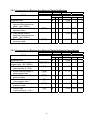
DS-470 SERIES OPERATING MANUAL
SECTION
INDEX
PAGE NUMBER
1.0.
GENERAL
1.1. Description
1
1
2.0.
SPECIFICATIONS
2.1. Technical Specifications
2.2. Physical Dimensions
2
2
3
3.0.
INSTALLATION
3.1. Unpacking
3.2. Inspection
3.3. Repackaging
3.4. DI-470 RS-232 Cable Installation
3.5. Platform Unlocking Procedure
4
4
4
4
5
6
4.0.
ELECTRICAL TEST
4.1. Set-Up Procedure
4.2. Keyboard & Display Test
7
7
7
5.0.
OPERATION
5.1. Keysheet and Display Layout
5.2. DS-470 Key Function Summary
"See below
5.3. Indicator Lamps
"See below
5.4. Operation Procedure Overview
5.5. Tare Reduction
5.5.1. Digital Tare
5.5.2. One Touch Tare
5.6. Set The Min And Max Values
5.6.1. Programming Of Minimum And Maximum Range By Numeric Key Entry
5.6.2. Programming Of Minimum And Maximum Range By Weighing
5.6.3. Programming Of Minimum And Maximum Range By Entering Target Weight
5.6.4. Programming Of Minimum And Maximum Range By Weighing Target Weight
5.7. Check Weighing Operation
5.7.1. Using Full Container
5.7.2. When Filling A Container
5.8. Clearing Min & Max Range
8
8
8
8
9
10
10
10
10-12
10
11
11
12
12-13
12
13
13
6.0.
DS-470 OPTIONS
6.1. RS-232 Option
6.2. Set Point
14-20
14-18
19-20
7.0.
MAINTENANCE, CALIBRATION, TEST PROCEDURE, SERVICE
7.1. Maintenance Procedures
7.2. Service & Repair
"See below
7.3. Specification List
7.4. Span Enable Switch
7.5. Internal Count
7.6. Calibration Mode
"See below
7.7. Error Messages
7.8. Shop Notes
21-31
21
22
23-27
28
28
29
29
30
"See pages 2,8, 25,26, 27 for revisions in this manual
DS-470 OPERATING MANUAL
1.0.
GENERAL
1.1. Features
The DS-470SS Check Weighing Scale offers a practical solution to a wide
range of weighing applications. There are a variety of weight capacities and
increments available. The display resolution is selectable from 1/3,000 to
1/15,000. It features keyboard calibration with auto-span and ON/OFF,
REZERO, TARE, for one touch tare and a numeric keyboard for digital tare
and set point entry. For a list of platform sizes and available capacities see
page 2.
This instruction manual will provide the user with all the information necessary
to understand, set-up and operate the DS-470 scale. Included in this manual
are descriptions, specifications, drawings, and operating instructions.
1
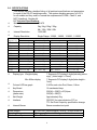
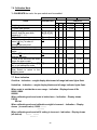
2.0. SPECIFICATIONS
This section includes a detailed listing of all pertinent specifications and parameters
for each of the DS-470 weighing scales. The system weighing accuracy is 0.02 %
for all models and they meet or exceed the requirements of OIML, Class III, and
NIST Handbook, Number 44.
Â
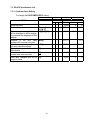
2.1 Technical Specifications
Model Name
DS-470
Â
Capacity
3kg / 6kg /15kg / 30kg
6lb / 15lb / 30lb / 60lb
Â
Internal Resolution
1/600,000
Â
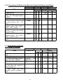
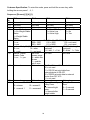
Display Resolution
Capacity
3LB
6lb
12lb
15lb
30lb
60lb
1/3000
e=0.001 lb
e=0.002 lb
Not avail.
e=0.005 lb
e=0.01 lb
e=0.02 lb
Single Range: 1/3000 , 1/6000 , 1/12000 , 1/15000
Display Resolution
1/6000
1/12000
1/15000
e=0.0005 lb
Not avail.
e=0.0002 lb
e=0.001 lb
e=0.0005 lb
Not avail.
e=0.002 lb
e=0.001 lb
Not avail.
Not avail.
Not avail.
e=0.001 lb
e=0.005 lb
Not avail.
e=0.002 lb
e=0.01 lb
e=0.005 lb
Not avail.
3kg
6kg
12kg
15kg
30kg
e=0.001kg
e=0.002 kg
Not avail.
e=0.005 kg
E=0.01 kg
e=0.0005g
e=0.001 kg
e=0.002 kg
Not avail.
e=0.005 kg
Â
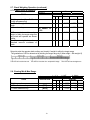
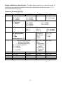
Display type Weight display
Min & Max display
Not avail.
e=0.0005 kg
e=0.001 kg
Not avail.
Not avail.
e=0.0002 kg
Not avail.
Not avail.
e=0.001 kg
e=0.002 kg
7 Segments FIP display 6 digits(including minus
sign) , (letter height = 13mm)
7 Segments FIP display 5 digits(letter height =
7mm)
Â
Colored LED bar graph
5 LEDs each color Red, Green, Yellow
Â
Key Board
18 mechanical keys
Â
Dimensions
(platter size)
256(W) x 320(D) x 87(H)mm
256(W) x 205(D)
Â
Net Weight
Approximately 3kg
Â
Interface
RS-232C for external device (PC) or
TTL Set Point Output by specification change
Â
Internal Buzzer
Buzzer sounds at set point
Power Source
Operating Temperature
Relative Humidity
AC 100/110V, 220/230/240V(+10% to –15%)50 or 60 Hz
-10° degrees Celsius to 40° degrees Celsius
15% ≈ 85% RH
2
2.2. Physical Dimensions
2.3. Color LED Bar Graph LEDs provide clear indication of weight condition between minimum and
maximum besides the digital weight display.
Target range is determined by entering 2 set points (min and max range.) The value can be
entered by any method described in section (5.6.) on pages 13 - 15. Set points alert the operator
with both auditory and visual signals if weight is within the target range.
The graduation of LED is determined by dividing the target range by 5 (Max weight – Min weight /5)
This LED is lit as the low min. This LED is lit as the min. acceptance range. This LED is lit as the high max.
3
3.0.
INSTALLATION
This section provides the information required for installation of the DS-470 weight
indicator.
The following steps accomplish installation.
1.
Unpacking
2.
Set-up Procedure
3.1.
Unpacking
Each component of the DS-470 is packed in a specially designed carton.
Remove each component from its carton, separate the component from its
polystyrene shell assembly and set aside. Inspect the carton interior to be
sure that all accessories have been removed from the carton. Inspect the
carton inner panels for accessories.
NOTE: Be sure to repack all materials within the carton set. Store the
cartons in a secure area so they can be available whenever shipment of the
scale is required.
3.2.
Inspection
Immediately after unpacking, a visual inspection of the instrument should be
performed. If any damage has been incurred during transportation the
shipper and DIGI MATEX INC. should be notified immediately. Instructions
for assessment of damage and further procedures will then be determined.
3.3.
Repackaging
If, at anytime, the DS-470 check weighing scale must be returned for
modification, calibration, or repair, be sure that it is properly packed with
sufficient cushioning materials.
Whenever possible, the original carton assembly should be retained for this
purpose. Any damage caused by improper packaging will not be covered by
warranty.
3.4.
RS – 232 Cable Installation & Assembly
The DS-470 has RS-232 & set points as a standard feature and are spec
selectable, pole mounting kit comes with all the necessary hardware and
assembly is easy. See page 6 for details.
3.5.
DS-470 SS Unlocking
The unlocking procedure is Included on page 6.
4
3.4. RS-232 Cable Installation
5
3.5.1. DS-470 SS Unlocking Procedure
6
4.0. ELECTRICAL TEST
4.1. Set-Up Procedure
This part of the procedure is used to verify proper operation of the weighing scale.
Place the scale on a reasonably level surface. Level the scale using the adjustable
legs and the level bubble guide.
Connect the AC power source, and press the "ON/OFF " key, the display will
momentarily show all digits from 0 to 9 in a "count-up" mode. Then the display will
blank, show all "8's", and enter the regular operating display.
If at any time the scale displays erratic data, it may be caused by a power transient.
Turn the scale "off" and momentarily unplug it from the wall outlet. Then restart, by
plugging the scale back in and pressing the "ON/OFF " key.
4.2. Keyboard and Display Test
This part of the procedure is used to verify proper operation of the various switches
and displays.
The following functions will be tested in this procedure:
A. Re-Zero
A. Tare Entry
B. Digital Tare Entry
4.2.2. One Touch Tare
A. Press the "0" key and then the "TARE" key to reset any Tare.
B. Press “REZERO” key to re-zero the scale.
C. Place the empty container on the scale and press the "TARE" key
once. The weight display should now read zero with the empty container
on the scale.
4.2.3. Digital Tare Entry
A Press the "TARE" key.
B Press the "RE-ZERO" key. After resetting, the Displays will read zero.
C Enter the number 0.2 by using the keyboard. Then press the "TARE" key.
D The weight display will show the weight entered with a negative sign
indicating that the weight displayed is a Tare Weight.
7
OPERATION
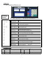
5.1. Keysheet and Display Layout
5.2. DS-470
Key Function
Summary
"Note: For Ver 1.19 and above Indicator lights in the weight window are as follows
ZERO TARE lb kg g oz - and the [kg/lb] key is now labeled [UNIT]
Numeric Keys :
Numeric Keys :
0-9
0-9
Re-Zero Key:
Re-Zero Key:
ENTER key:
ENTER key:
To return scale to zero point
To return scale to zero point
To enter the minimum & maximum
To enter
the minimum
weight
range
Set point & maximum
weight range Set point
Used to send data with RS-232 &
RS-232 &
Used to send
store data
specswith
in program
mode
Used to store specs in program mode
ON / OFF key:
ON / OFF key:
PERCENTAGE
PERCENTAGE
Key:
Key:
To turn on and off the power to the display
To turn on and off the power to the display
Used to min & max percent set point &
Used to min
& max
percent set point &
exit spec
mode
Used to exit spec mode
CLEAR key:
CLEAR key:
Used to clear data in display
Used to clear data in display
TARE key:
TARE key:
Kg/LB("now
Kg/LB("now
unit
change)
unit change)
Used for setting and clearing tare weight
Used for setting and clearing tare weight
Switch between pounds, kilograms (" now also grams and
Switch
pounds,
kilograms
ouncesbetween
see spec
3)
ver1.19 (" now also grams and
ounces see spec 3)
ver1.19
MIN & MAX key:
MIN & MAX key:
5.3. Indicator Lamps
Indicators
Function
ZERO Lamp When weight is at zero
NET TARE Lamp When a tare is programmed
lb
Lb Lamp
When pounds is selected
Indicators
kg
Kg Lamp
Function
g
oz
When grams is selected
When ounces is selected
8
g Lamp
oz Lamp
When kilograms is selected
5.4.
Operation Procedure Overview
Step 1. ----- Press ON/OFF key to turn on the power.
The numerical display windows will begin with all 0’s and scroll through to all 8’s. The
DS-470 is ready to weigh as shown below.
0
0
0.0000
Note: Please set scale on a firm surface and turn adjusting legs until bubble comes
to the center of the level indicator.
Step 2. ----- 5.5. Tare Subtraction.
Step 3. ----- 5.6. Set The Min And Max Values.
Step 4. ----- 5.7. Check Weighing Operation.
Step 5. ----- 5.8. Clearing Min & Max Range
9
SCALE OPERATION
5.5. Tare Reduction
5.5.1. Preset Tare Operation
indicators
TASK
1 :
OPERATION
INDICATORS
1
Weighing mode
1. Enter tare weight with numeric
keys. (Ex. Tare 0.900 lb.)
2. Subtract tare weight.
[9] [0] [0]
2
•
•
[T]
2 : NET
3
•
•
3 : Îgh
DISPLAY
WEIGHT
MIN
MAX
0.000
0.900
0
0
0
0
−0.900
0
0
5.5.2. One Touch Tare Operation
indicators
TASK
1 :
OPERATION
INDICATORS
1
Weighing mode
1. Place tare weight on platter.
(Ex. Tare 0.500 lb.)
2. Press the tare key.
3. Remove the weight from
platter.
2 : NET
2
3
•
[T]
•
•
•
3 : Îgh
DISPLAY
WEIGHT
MIN
MAX
0.000
0.500
0
0
0
0
0.000
−0.500
0
0
0
0
"NOTE: To clear a tare value, press [T] key with no weight on platter.
"NOTE: When setting min & max values the scale will not allow weight unit to
change, the [UNIT] key is disabled until both min & max values have been selected.
The min & max values will then be converted to weight unit selected.
5.6. Set the min and max values.
5.6.1. Programming Of Minimum And Maximum Range By Numeric Key Entry
indicators
TASK
1 :
OPERATION
INDICATORS
1
Weighing mode
1. Enter minimum weight value
by using the numeric keys.
(ex. 0.156 lb.)
2. Press MIN key to set the
Minimum Value.
3. Enter maximum weight value
by using the numeric keys.
(ex. 0.183 lb.)
4. Press MAX key to set the
Maximum Value.
[1] [5] [6]
2 : NET
•
2
3
•
•
[MIN]
•
•
[MAX]
10
3 : Îgh
DISPLAY
WEIGHT
0.000
0.156
MIN
MAX
0
0
0
0
0.000 0.156
0
0.183 0.156
0
0.000 0.156 0.183
5.6.2. Programming Of Minimum And Maximum Range By Weighing
indicators
TASK
1 :
OPERATION
INDICATORS
1
Weighing mode
1. Place weight equal to
minimum value desired on
platter. (Ex.0.209 lb.)
2. Press MIN key to set the
minimum value.
3. Place weight equal to
maximum value desired on
platter. (Ex.0.309 lb.)
4. Press MAX key to set the
maximum value.
2 : NET
2
3
3 : Îgh
DISPLAY
WEIGHT
MIN
0.000
0.209
•
[MIN]
MAX
0
0
0
0
0.209 0.209
0
0.309 0.209
0
0.309 0.209 0.309
[MAX]
5.6.3. Programming Of Minimum And Maximum Range By Entering Target Weight
indicators
TASK
1 :
OPERATION
INDICATORS
1
Weighing mode
1. Enter target weight with
numeric keys. (Ex.1.000 lb.)
2. Press % key.
(input memory is 1.0 lb.)
3. Select minimum weight %
using numeric keys
4. Press MIN key to set the
minimum value.
5. Select maximum weight %
using numeric keys
6. Press MAX key to set the
maximum value.
7. Press % key.
(input memory is 1.0 lb.)
2 : NET
2
3
3 : Îgh
DISPLAY
WEIGHT
MIN
MAX
•
0.000
1.000
0
0
0
0
[%]
•
P 0
0
0
[1] [2]
•
P 12
0
0
[MIN]
•
P 12 0.880
0
[5]
•
P 5 0.880
0
[MAX]
•
P 5 0.880 1.050
[1] [0] [0] [0]
•
•
[%]
11
0.000 0.880 1.050
5.6.4. Programming Of Minimum And Maximum Range By Weighing Target Weight
Indicators
TASK
1 :
OPERATION
INDICATORS
1
Weighing mode
1. Place target weight on the
platter. (Ex. The target weight is
0.620 lb.)
2. Press % key.
3. Press minimum weight percent
by using numeric keys. ( Ex.
10%)
4. Press MIN key to set the
minimum value. (Ex. 0.620 x
(100% - 10%) = 0.558)
5. Press maximum weight
percent by using the numeric
keys. (Ex. 15%)
6. Press MAX key to the
maximum value. (Ex. 0.620 x
(100% + 15%) = 0.713)
7. Press % key to enter weighing
mode.
2 : NET
2
3 : Îgh
DISPLAY
3
WEIGHT
MIN
MAX
•
0.000
0.000
0
0
0
0
[%]
[1] [0]
•
•
P 0
P 10
0
0
0
0
[MIN]
•
P 10 0.558
0
[1] [5]
•
P 15 0.558
0
[MAX]
•
P 15 0.558 0.713
•
0.000 0.558 0.713
•
5.7. Check Weighing Operation
5.7.1. Using full container
Indicators
TASK
1 :
OPERATION
INDICATORS
1
Weighing mode. (from previous
step)
1. Place full container on scale
2. Enter tare weight with numeric
keys. (Ex. Tare 0.900 lb.)
3. Subtract tare weight.
2 : NET
2
3
3. If weight is within the target range
the set points will operate as
shown on page 19.
4. Once weight has been
checked remove container of
parts.
12
MIN
MAX
0.558
0.713
1.595
0.900
0.558
0.558
0.713
0.713
•
0.695
0.558
0.713
•
0.695
0.558
0.713
0.000
0.558
0.713
•
•
DISPLAY
WEIGHT
0.000
•
[9] [0] [0]
as
shown in 5.3.1.
[T] as shown in
5.3.1.
3 : Îgh
5.7. Check Weighing Operation (continued)
5.7.2. When filling a container
Indicators
TASK
1 :
OPERATION
2 : NET
INDICATORS
1
Weighing mode. (from 5.4.4. min
•
& max programming)
1. Place empty container on
scale
2. Press tare key.
as shown in •
5.3.2.
3. Place parts in container, when
weight is within the target range the
set points will operate as shown
below.
4. Once weight has been
•
checked remove container of
parts.
2
3
3 : Îgh
DISPLAY
WEIGHT
MIN
MAX
0.000
0.558
0.713
0.500
0.558
0.713
•
0.000
0.558
0.713
•
0.695
0.558
0.713
•
0.000
0.558
0.713
Set points alert the operator both auditory and visually if weight is within the target range.
The graduation of LED is determined by dividing the target range by 5 (Max weight – Min weight /5)
This LED is lit as the low min. This LED is lit as the min. acceptance range
This LED is lit as the high max.
5.8. Clearing Min & Max Range
Indicators
TASK
1 :
OPERATION
INDICATORS
1
Weighing mode
1. Press minimum key
2. Press maximum key
[MIN]
[MAX]
13
2 : NET
•
•
•
2
3
3 : Îgh
DISPLAY
WEIGHT
0.000
0.000
0.000
MIN
0.558
0
0
MAX
0.713
0.713
0
6.0. RS-232
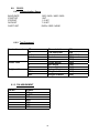
6.0.1. Communication Specs
BAUD RATE
START BIT
STOP BIT
DATA BIT
PARITY BIT
1200 / 2400 / 4800 / 9600
1 BIT
1 / 2 BIT
7 / 8 BIT
EVEN / ODD / NONE
6.0.2. Text Command
Termination code
Data
Header code
Weight stable
CR
LF
0-9
Period
Comma
:
0
4
B
SOH
NUL
The end of data
The end of text
Numeric data
Period
Comma
Gross weight
Net weight
Tare weight
Set –point status
Weight stable
Weight unstable
6.1.3. PIN ASSIGNMENT
PIN NO.
1
2
3
4
5
6
7
SIGNAL
SP1
S GND
SP2
RXD
TXD
CTS
RTS
14
0DH
0AH
(30H – 39H)
(2EH)
(2CH)
(3AH)
(30H)
(34H)
(42H)
(01H)
(00H)
6.1.4. COMMUNICATION METHOD
By specification setting (Spec 59 bit 2 & 3), the communication method may be
selected from Stream (continuous output), Manual (output by pressing [½
½] key,
and Command (output by command from external device).
6.1.4.1. STREAM
Data is transmitted to external device continuously.
DATA STREAM:
The SPEC to select whether weight stable status or not by specification setting
(Spec 53 bit 3).
Example: without stable flag
STX
Header
Gross Weight
CR
Header
Net Weight
CR
1
1
5
1
1
5
1
Header
1
STX
1
Tare Weight
5
CR
1
Header
1
Example: with stable flag
Stable
Header
Gross Weight
1
1
5
Header
1
Tare Weight
5
CR
1
Set-point Status
2
CR
1
Header
1
Header
1
Set-point Status
2
CR
1
LF
1
Net Weight
5
CR
1
CR
1
LF
1
Weight Stable Status:
Status
Data
Stable
SOH (01 H)
Un-stable
NUL (00 H)
Set-point status
Status
Set-point is not programmed
Weight < Set-point 1
Set-point 1 < Weight <Set-point
Set-point 2 < Weight
Data
B
B
B
B
1
1
0
0
1
1
1
0
The Data is transmitted when the machine is in operation mode. While entering
numeric data, the transmission would be stopped.
15
6.1.4.2. MANUAL
Data is output by pressing [½
½] key. User may select to transmit the data right away
or to hold the command until weight becomes stable (from Spec 59 bit 1). If weight
is not back to stable within a certain interval (from Spec 59 bit 0), TIME OUT ERROR
will appear on the display. The two communication methods may be selected in this
mode.
6.1.4.2.1. MANUAL (METHOD 1)
DATA FORMAT:
Example: By pressing [½
½] key.
STX
Header
Gross Weight
1
1
5
Header
1
Tare Weight
5
CR
1
CR
1
Header
1
16
Header
1
Net Weight
5
Set-point Status
2
CR
1
CR
1
LF
1
6.1.4.2.2. MANUAL (METHOD 2)
The data text can be selected without headers or with headers (by setting Spec 56
bit 3)
DATA FORMAT:
Example: Without header codes
Gross Weight
CR
Net Weight
CR
Tare
Weight
CR
LF
5
1
5
1
5
1
1
Example: With header codes
STX
Header
Gross Weight
1
1
5
Header
1
Tare Weight
5
CR
1
CR
1
Header
1
17
Header
1
Net Weight
5
Set-point Status
2
CR
1
CR
1
LF
1
6.1.4.3. COMMAND
Data is transmitted by receiving ENQ from external device. By specification setting
(Spec 59, Bit 1), it is to select to transmit the data right away or to hold the command
until weight becomes stable. If weight is not back to stable within a certain interval
(by specification setting Spec 59 bit 0), TIME OUT ERROR will appear on the
display.
Example:
STX
1
Header
1
Header
1
Tare Weight
5
Gross Weight
5
CR
1
CR
1
Header
1
18
Header
1
Net Weight
5
Set-point Status
2
CR
1
CR
1
LF
1
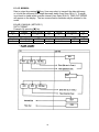
6.2. Transmit Set-Point Data
6.0.1. Transmit Set-Point Data From External Device
If Set-point data from an external device spec(spec 53 bit 2) is enabled and when
MAX key is pressed without entering numeric data I Operation mode, the scale would
send ENQ data and the external device would send the set-point data back.
TEXT COMMAND
Termination code
CR
LF
Data
0 –9
Period
Header code
Comma
F
H
DATA FORMAT:
Header
Set-point 1
1
5
CR
1
The end of data
The end of text
Numeric data
Period
0DH
0AH
(30H – 39H)
(2EH)
Comma
Set-point 1
Set-point 2
(2CH)
(46H)
(48H)
Header
1
19
Set-point 2
5
CR
1
LF
1
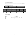
6.0.2. Transmit Set-Point Data To External Device
If Set-point data to an external device spec (spec 53 bit 2 ) is enabled and when
MAX key or MIN key is pressed in the in Operation mode, the scale would send DC2
or DC4 and the external device would receive the set-point data.
TEXT COMMAND
Termination code
CR
LF
Data
0 –9
Period
Comma
F
H
Header code
The end of data
The end of text
Numeric data
Period
0DH
0AH
(30H – 39H)
(2EH)
Comma
Set-point 1
Set-point 2
(2CH)
(46H)
(48H)
DATA FORMAT:
Example 1: Send MINimum set -point by pressing [MIN] key and scale sends DC2 to
external device.
STX
Header
MIN Set-point
CR
LF
1
1
5
1
1
Example 2: Send MAXimum set -point by pressing [MAX] key and scale sends DC4
to external device.
STX
1
Header
1
MAX Set-point
5
20
CR
1
LF
1
7.0.
MAINTENANCE, CALIBRATION, TEST PROCEDURE & SERVICE
This section contains information and instructions concerning maintenance of the
DS-470 check weighing scale.
Preventive maintenance consists of periodically cleaning the external surfaces of
the instrument and should be performed as often as operating conditions warrant.
The calibration procedure is designed to be an aid in maintaining the scale accuracy
within specifications. The calibration procedure may also serve as a performance
test procedure.
CAUTION: DO NOT ATTEMPT ANY SERVICE WHILE THE INSTRUMENT IS
CONNECTED TO THE POWER LINES.
7.1. Maintenance Procedures
7.1.1. Exterior Maintenance
The exterior surfaces of the counting scale can be easily cleaned using
soap and water. However, extreme caution should be used so that there is
no possibility of water penetration into the scale electrical or mechanical
sections. A damp cloth or sponge is suggested. NEVER USE ACETONE,
MEK, OR SIMILAR SOLVENTS ON THE PLASTIC HOUSING AS THEY
WILL ETCH THESE SURFACES.
For grease or other difficult spots, a chlorothane or naptha based cleaner
may be used. Never use any solvents on the front or rear panels.
Accumulations of dust or direct particles between the pins of the
connectors may be removed by using dry forced air or a small dry brush.
7.1.2. Internal Maintenance
Internal maintenance is not normally required and if it is, should not be
attempted except by a qualified, authorized service technician.
7.1.3. Calibration
The following procedure should be followed periodically (every six to
twelve months is suggested) to determine that the scale is functioning in all
modes.
a.
Electrical
Follow section 4.0 through all its steps
21
7.1.3 Continued
b.
Accuracy
Weighing: The scale weighing accuracy can be determined by
applying various known weights to the platform. Because of the
scale's very high accuracy, only weights that are certifiably more
accurate than the scale's specifications should be used in testing
for accuracy. (NBS class "F" or higher)
Since the scale owner does not normally have such certifiable
weights available to him, it is suggested that the customer call
their authorized
DIGI dealer.
7.2.
Service & Repair
No service or repair should be attempted except by qualified personnel, and
not until it has been positively determined that the counting scale requires
such service. All service should be done in a clean, dry, dust-proof area.
22
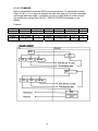
7.3. DS-470 Specification List
7.3.1. Customer Spec Setting
To change the CUSTOMER SPEC setting
Indicators
TASK
1 :
OPERATION
INDICATORS
1
Weighing mode
Enter customer spec mode
[Re-zero]
[1] [4] [1]
Enter new spec data. Old data [0] [0] [1] [0]
will be displayed in MAX window,
new data will be displayed in MIN
window.
Advance to the next spec [MAX]
number, will not save new data.
Returns to previous spec, this will [MIN]
not save new data entered.
Clears the data to all 0’s in the [C]
MIN window.
Advance to the next spec [½
½]
number and save new data.
Save spec changes and exit to [%]
weighing mode.
23
2 : NET
•
2
3
3 : Îgh
DISPLAY
WEIGHT
MIN
MAX
0.000
SPC 50
0
0
0000
SPC 50
0010
0000
SPC 51
1111
SPC 50
0010
SPC 50
0000
•
0.000
0
0
•
0.000
0
0
Customer Specification: To enter this mode, press and hold the re-zero key, while
holding the re-zero press 1 , 4 , 1.
Sequence: [Re-zero] [1] [4] [1].
Spec
no.
50
51
52
53
54
55
56
57
58
59
Bit 3
Bit 2
Not used
Not used
Not used
Not used
Not used
Not used
Stream Method
Not used
0 = No Weight Stable
Status
1 = Weight Stable
Status
RS-232 connection
0 = no
000 = 1200
1 = yes
001 = 2400
Parity Bit (Optional)
00 = no
10 = even
01 = odd
11 = not used
Manual 2 Mode
Set Point
Header Code
buzzer range
0 = no , 1 = yes
0 = within min
& max
1 = outside
min & max
Not used
Not used
Not used
Bit 0
Not used
Not used
Not used
Set Point TTL Output
0 = Active Low
1 = Active High
Not used
Not used
Not used
Set Point Buzzer
0 = No
1 = Yes
Baud Rate For RS-232 Option
010 = 4800
100 = not used
011 = 9600
101 = not used
RS-232 stop bit
RS-232 data length
(optional)
(optional)
0 = 2 bits , 1 = 1 bit
0 = 8 bits , 1 = 7 bits
Not used
Not used
Not used
RS-232 Mode
00 = stream
01 = manual 1
Bit 1
10 = manual 2
11 = command
24
Set Point External Communication
00 = not used
01 = RS-232 set point data from
external device to DS-470
10 = RS232 set point data to external
device from DS -470
11 = not used
Not used
Not used
Manual Mode By
Delay For Time –out
½Key Press
Error
0 = transmit right
0 = 3 seconds
away
1 = 5 seconds
1 = transmit after
weight stable
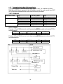
7.3.2. Weights & Measures Spec Setting
To change the WEIGHTS & MEASURES SPEC setting
Indicators
TASK
1 :
OPERATION
INDICATORS
1
Weighing mode
Enter weights & measures spec mode
[Re-zero]
[1] [4] [2]
Enter new spec data. Old data will be [0] [0] [1] [0]
displayed in MAX window, new data will
be displayed in MIN window.
Advance to the next spec number, will not
save new data.
Returns to previous spec, this will not
save new data entered.
Clears the data to all 0’s in the MIN
window.
Advance to the next spec number and
save new data.
Save spec changes and exit to weighing
mode.
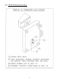
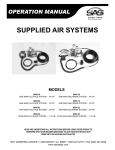
LOCATION OF SPAN SWITCH
1.
2.
3.
4.
2 : NET
2
•
3
3 : Îgh
DISPLAY
WEIGHT
MIN
MAX
0.000
SPC 00
0
0
0000
SPC 00
001
0
0000
[MAX]
SPC 01
1111
[MIN]
SPC 00
0010
[C]
SPC 00
0000
[½
½]
•
0.000
0
0
[%]
•
0.000
0
0
"new information
Ver 1.19
Remove access cover with four knurled and slotted screws.
Remove hex head screw in hole “A”.
Insert long thin rod into hole “A”.
Push span switch. Display shows S-On, the W & M specs and calibration can now be
performed.
When calibration is finished and the scale is ready to be sealed
1. Install hex screw in hole “A” to cover span switch.
2. Install access cover
3. Install supplied hex screw in hole “B”, replacing one of the knurled and slotted screws.
4. Install wire seal from screw “B” to screw “C”.
25
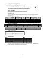
Weight and Measures Specification : The Span Switch must be on to enter this mode. To
enter this mode, press and hold the Re-zero Key, while holding the Re-zero press 1, 4, 2,
then release the Re-zero key.
Sequence: [Re-zero] [1] [4] [2].
Spec No.
0
1
2
3
Bit 3
Bit 2
Bit 1
Bit 0
Display Resolution
Not used
0 = single range
1 = multi range
00 = 1/3000
10 = 1/12000
01 = 1/6000
11 = 1/15000
Display
Weight Decimal Point Position
0 = decimal pt
000 = 00000
011 = 00.000
1 = comma
001 = 0000.0
100 = 0.0000
010 = 000.00
Not used
Minimum Display
000 = 1
010 = 5
100 = not used
001 = 2
011 = 10
101 = not used
Not used
IR Mode
Change Units
Change Units
Protected
By
(lb.↔ kg)
(lb.↔ kg ↔g ↔ oz)
Span Switch
0 = no
0 = no
0
=
no
1 = yes
1 = yes
1 = yes
" new spec ver1.19
4
Set-Point Buzzer Range
(Outside Min & Max)
/Print Range(RS-232)
00 = >net 5d & gross 21d
01 => net 1d
10 => net 19d
11 => net 20d
5
6
7
8
9
Not used
Not used
Not used
Not used
Not used
Not used
Not used
Not used
Not used
Not used
26
Auto Tare Clear
Range
0 = gross over
20d and net
over 4d
1 = gross over
0d and net
over 1d
Not used
Not used
Not used
Not used
Not used
Not used
Not used
Not used
Not used
Not used
Not used
Weight and Measures Specification (continued):
Spec No.
20
Bit 3
Tare Addition
0 = yes
1 = no
21
Not used
22
23
24
Not used
Not used
25
26
27
28
Value
0000
0001
0010
0011
0100
0101
0110
0111
1000
1001
1010
1011
1100
1101
1110
1111
Not used
Not used
Not used
Not used
29
Not used
Bit 2
Dual Range
0 = multi gross
1 = multi net
Bit 1
Bit 0
Digital Tare
Tare Range
Setting
0 = 50% of max
0 = no
1 = 100% of max
1 = yes
Not used
Digital Tare
Tare Auto Clear
Rounding
0 = no
0 = tare exactly 1 = yes
1 = round to
nearest
increment
Not used
Not used
Not used
Not used
Not used
Not used
Load Cell Sensitivity Selection (mV/V)
Minimum
Maximum
3.46
4.00
3.00
3.46
2.59
3.00
2.25
2.59
1.95
2.25
1.69
1.95
1.46
1.69
1.27
1.46
1.09
1.27
0.95
1.09
0.82
0.95
0.71
0.82
0.61
0.71
0.53
0.61
0.48
0.53
0.40
0.46
Not used
Not used
Not used
Not used
Not used
Not used
Not used
Not used
Not used
Not used
Re-zero
Power-On Start
Tracking Range Range
0 = +/- 2%
0 = +/- 10%
1 = unlimited
1 = unlimited
Not used
Not used
Enter weight for
Calibration
0 = no
1 = yes
"new spec
ver1.10+
27
7.4. Span Switch Status
To check position of SPAN SWITCH
Indicators
TASK
1 :
OPERATION
INDICATORS
1
Weighing mode
1. Press & hold Re-zero while
pressing 2, 8, 4
[Re-zero]
[2] [8] [4]
Scale returns to weighing mode
after 3 seconds.
2 : NET
2
3
3 : Îgh
DISPLAY
WEIGHT
MIN
MAX
0.000
0
0
S-ON or
S-OFF
S-ON = Span switch enabled
S-OFF = Span switch disabled
0.000
0
0
•
•
7.5. Internal Count
To check the INTERNAL COUNT of the A/D
Indicators
TASK
1 :
OPERATION
INDICATORS
1
Weighing mode.
1. To display the internal count,
press & hold Re-zero while
pressing 0, 0, 9.
2. To view A/D count.
3. to toggle back to internal
count.
4. Exit to weighing mode.
[Re-zero]
[0] [0] [9]
2 : NET
•
2
3
3 : Îgh
DISPLAY
WEIGHT
0.000
00000
MIN
MAX
0
0
0
0
10000
00000
[C]
[C]
•
[%]
28
0.000
7.6. Calibration Mode
To CALIBRATE the scale, the span switch must be enabled.
Indicators
TASK
1 :
OPERATION
INDICATORS
1
Weighing mode.
1. Press Span Switch
2. To enter calibration mode,
press & hold Re-zero while
pressing 8, 7, 1, 5.
3. Press Re-zero key.
4. With no weight on the platter,
press [½
½]key in order to
calibrate the zero point.
Span Calibration
5. Place capacity test weight on
platter
6. Press [½
½]key in order to
calibrate the span.
7. After a few seconds, the scale
shows the span counts.
8. Remove the weight. Press [%]
key to exit calibration mode.
9. Calibration finished. Press
Span Switch to return to the
weighing mode.
2 : NET
•
[Re-zero]
[8] [7] [1] [5]
2
3
3 : Îgh
DISPLAY
WEIGHT
MIN
MAX
0.000
0
S-on
90614 CAL00
0
0.002
90614 CAL00
0.000
--------- -----
[Re-zero]
[½
½]
0.000 CALSP 87342
0.271 CALSP 66000
[½
½]
[%]
-----
----- -----
60000
SPAn CoUnt
•
S-on
•
0.000
0
7.7. Error Indication
Overflow – Indication – weight display blanks and all range indicator lights flash.
Underflow – Indication – weight display blanks and all range indicator lights flash.
When scale is outside the re-zero range – Indication –Display shows all 8’s
88888 88888
888888
When calibrating scale and scale is behind zero – Indication – Display shows
PrESS
SPr Int
When calibrating scale and calibration weight is incorrect – Indication – Display
shows (incorrect value) 10000 - - - - -----When calibrating scale and mV/V setting is incorrect – Indication – Display shows
(all dashes)
----- ---------29
0
7.8. Shop Notes
30
DS-470 Limited Warranty
Rice Lake Weighing Systems (RLWS) warrants that all RLWS equipment and systems properly installed by a
Distributor or Original Equipment Manufacturer (OEM) will operate per written specifications as confirmed
by the Distributor/OEM and accepted by RLWS. All systems and components are warranted against defects
in materials and workmanship for one year.
RLWS warrants that the equipment sold hereunder will conform to the current written specifications
authorized by RLWS. RLWS warrants the equipment against faulty workmanship and defective materials. If
any equipment fails to conform to these warranties, RLWS will, at its option, repair or replace such goods
returned within the warranty period subject to the following conditions:
•
Upon discovery by Buyer of such nonconformity, RLWS will be given prompt written notice with a detailed explanation
of the alleged deficiencies.
•
Individual electronic components returned to RLWS for warranty purposes must be packaged to prevent electrostatic
discharge (ESD) damage in shipment. Packaging requirements are listed in a publication, “Protecting Your Components
From Static Damage in Shipment,” available from RLWS Equipment Return Department.
•
Examination of such equipment by RLWS confirms that the nonconformity actually exists, and was not caused by
accident, misuse, neglect, alteration, improper installation, improper repair or improper testing; RLWS shall be the sole
judge of all alleged non-conformities.
•
Such equipment has not been modified, altered, or changed by any person other than RLWS or its duly authorized repair
agents.
•
RLWS will have a reasonable time to repair or replace the defective equipment. Buyer is responsible for shipping charges
both ways.
•
In no event will RLWS be responsible for travel time or on-location repairs, including assembly or disassembly of
equipment, nor will RLWS be liable for the cost of any repairs made by others.
THESE WARRANTIES EXCLUDE ALL OTHER WARRANTIES, EXPRESSED OR IMPLIED,
INCLUDING WITHOUT LIMITATION WARRANTIES OF MERCHANTABILITY OR FITNESS
FOR A PARTICULAR PURPOSE. NEITHER RLWS NOR DISTRIBUTOR WILL, IN ANY EVENT,
BE LIABLE FOR INCIDENTAL OR CONSEQUENTIAL DAMAGES.
RLWS AND BUYER AGREE THAT RLWS’S SOLE AND EXCLUSIVE LIABILITY HEREUNDER
IS LIMITED TO REPAIR OR REPLACEMENT OF SUCH GOODS. IN ACCEPTING THIS
WARRANTY, THE BUYER WAIVES ANY AND ALL OTHER CLAIMS TO WARRANTY.
SHOULD THE SELLER BE OTHER THAN RLWS, THE BUYER AGREES TO LOOK ONLY TO
THE SELLER FOR WARRANTY CLAIMS.
No terms, conditions, understanding, or agreements purporting to modify the terms of this warranty shall have any legal effect unless
made in writing and signed by a corporate officer of RLWS and the Buyer.
© 2002 Rice Lake Weighing Systems, Inc. Rice Lake, WI USA. All Rights Reserved.
RICE LAKE WEIGHING SYSTEMS
• 230 WEST COLEMAN STREET • RICE LAKE, WISCONSIN 54868 • USA
1