1
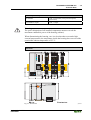
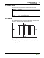
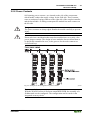
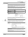
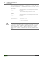
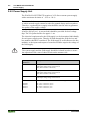
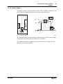
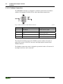
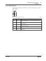
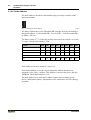
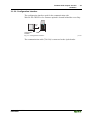
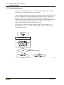
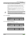
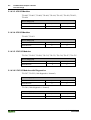
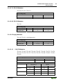
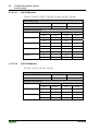
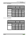
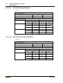
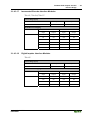
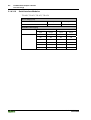
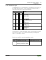
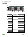
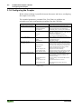
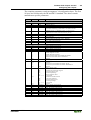
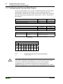
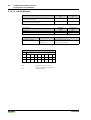
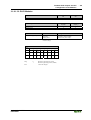
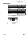
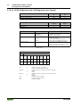
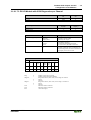
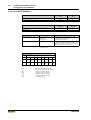
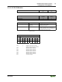
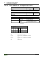
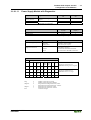
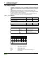
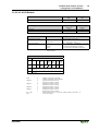
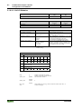
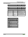
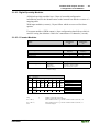
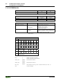
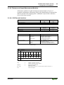
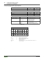
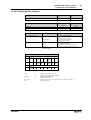
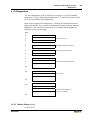
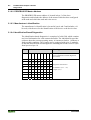
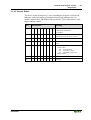
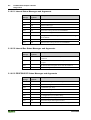
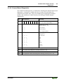
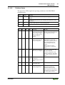
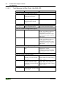
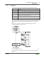
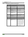
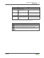
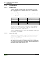
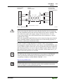
Fieldbus ECO-Coupler 750-343
Configuration of I/O Modules
• 83
3.1.8.3 Digital Specialty Modules
All digital specialty modules have 2 byte of extended configuration
information used for the identification on the internal bus and the creation of a
mapping table.
With input modules (counter), 2 bytes follow which are reserved for future
options.
For output modules (PWM output), 6 byte configuration data follows which is
used for saving the substitute values for a maximum of 2 channels (2 words).
3.1.8.3.1 Counter Modules
Module
Identification
hex
Identification
dec
0xF2
242
Input Image
in [byte]
6
6
Output Image
in [byte]
6
6
750-404, 750-638
Process Image
Internal bus
PROFIBUS DP
Parameter
Value
Meaning
plug fitted*)
not plug fitted
The I/O module process data is:
- supplied by the I/O module
- set to zero by the Coupler
I/O module is physically
*)
Default settings
Parameter
Offset
Information
0
7
6
5
4
3
2
1
0
0
Plug
0
0
0
0
0
7
6
5
4
3
2
1
0
0
1
1
1
ID5
ID5
ID4
ID4
ID3
ID3
ID2
ID2
ID1
ID1
ID0
ID0
15
14
13
12
11
9
8
7
5
4
3
2
1
0
1
2
0
ID 750-404 *)
ID 750-638 **)
reserved
3
7
6
reserved
Plug5
ID5 .. ID0 *)
ID5 .. ID0 **)
Italic
WAGO-I/O-SYSTEM 750
PROFIBUS
0
1
Module is physically not present
Module is physically present (default)
Order number less 350 (e.g. 750-404 would be coded as (404-350) = 54
Order number less 630 (e.g. 750-638 would be coded as (638-630) = 8
Cannot be changed