1
The WAGO-I/O-SYSTEM 750
Power Supply
• 23
2.6 Power Supply
2.6.1 Isolation
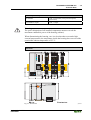
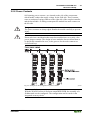
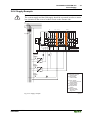
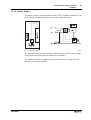
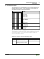
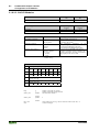
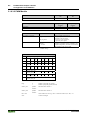
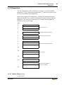
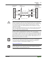
Within the fieldbus node, there are three electrically isolated potentials.
· Operational voltage for the fieldbus interface.
· Electronics of the couplers / controllers and the bus modules (internal bus).
· All bus modules have an electrical isolation between the electronics
(internal bus, logic) and the field electronics. Some analog input modules
have each channel electrically isolated, please see catalog.
Potential of the system supply
Electrical isolation
to the field level
Fieldbus
Interface
T 6,3 A
250 V
per module
DC
DC
Elektronic
per channel
Potential
Fieldbus interface
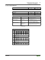
Fig. 2-10: Isolation
Potentials
in the field level
g0xxx11e
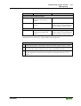
Attention
The ground wire connection must be present in each group. In order that all
protective conductor functions are maintained under all circumstances, it is
recommended that a ground wire be connected at the beginning and end of a
potential group. (ring format, please see chapter "Grounding Protecti"). Thus,
if a bus module comes loose from the node during servicing, then the
protective conductor connection is still guaranteed for all connected field
devices.
When using a joint power supply unit for the 24 V system supply and the
24 V field supply, the electrical isolation between the internal bus and the
field level is eliminated for the potential group.
WAGO-I/O-SYSTEM 750
PROFIBUS