1
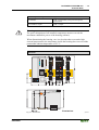
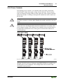
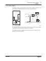
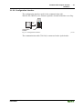
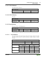
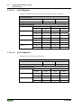
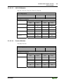
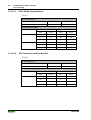
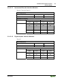
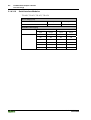
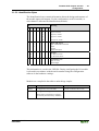
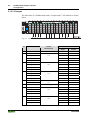
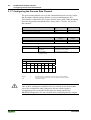
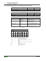
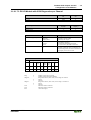
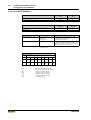
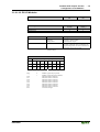
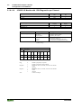
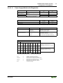
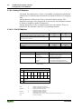
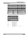
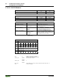
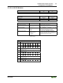
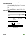
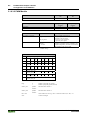
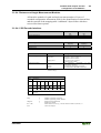
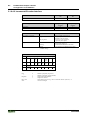
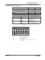
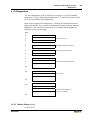
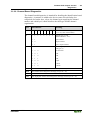
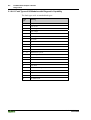
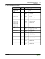
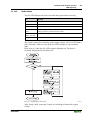
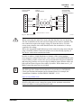
Fieldbus ECO-Coupler 750-343
Configuration
• 59
3.1.5 Configuration
The configuration of the node is performed in accordance with the physical
placement of the Fieldbus Coupler and I/O modules.
The Fieldbus Coupler or the process data channel is to be configured on the
first slot.
The other slots are configured in accordance with the physical placement of
the I/O modules. Here only I/O modules with process data are relevant. The
supply modules without diagnostics, bus internal system supply modules, field
side connection modules, separation modules and termination modules are to
be ignored for the configuration because they do not provide any process data.
There are one or two entries in the hardware cataloge for each I/O module.
The module appear as 750-xyz ..., for example 750-400 2 DI/24 V DC/3.0 ms.
For all binary modules an additional entry is made, *750-xyz .... When using
this notation the Coupler adds the binary information to the current module in
a byte which was previously opened with 750-xyz .... The use of a „*“ module
is only permitted when the number of channels is less than or equal to the
remaining bits in the previously opened byte. The binary I/O modules
combined in a byte can be arranged at separate locations, i.e. binary I/O
modules with a different signal type or also byte orientated I/O modules can
be combined.
WAGO-I/O-SYSTEM 750
PROFIBUS