1
24 PORTS 10/100BASE-T MANAGEMENT
ETHERNET SWITCH WITH 2 1000BASE-X
COMBO SFP SLOTS UPLINK
Model: 500-7624FE2GC
0
SIGNAMAX a.s.
Office: Vlarska 22, 627 00 Brno, CZ
T:+420 533 338 854 l F:+420 533 338 883 l www.signamax.eu
Trademarks
Contents subject to revise without prior notice.
All other trademarks remain the property of their respective owners.
Copyright Statement
Copyright 2009, All Rights Reserved.
This publication may not be reproduced as a whole or in part, in any way whatsoever unless prior
consent has been obtained from Company.
FCC Warning
This equipment has been tested and found to comply with the limits for a Class-A digital device,
pursuant to Part 15 of the FCC Rules. These limitations are designed to provide reasonable
protection against harmful interference in a residential installation. This equipment generates uses
and can radiate radio frequency energy and, if no installed and used in accordance with the
instructions, may cause harmful interference to radio communications. However, there is no
guarantee that interference will not occur in a particular installation. If this equipment does cause
harmful interference to radio or television reception, which can be determined by turning the
equipment off and on, the user is encouraged to try to correct the interference by one or more of the
following measures:
Reorient or relocate the receiving antenna.
Increase the separation between the equipment and receiver.
Connect the equipment into a different outlet from that the receiver is connected.
Consult your local distributors or an experienced radio/TV technician for help.
Shielded interface cables must be used in order to comply with emission limits.
Changes or modifications to the equipment, which are not approved by the party responsible for
compliance, could affect the user’s authority to operate the equipment.
Copyright © 2009 All Rights Reserved.
Company has an on-going policy of upgrading its products and it may be possible that information in
this document is not up-to-date. Please check with your local distributors for the latest information.
No part of this document can be copied or reproduced in any form without written consent from the
company.
Trademarks:
All trade names and trademarks are the properties of their respective companies.
1
SIGNAMAX a.s.
Office: Vlarska 22, 627 00 Brno, CZ
T:+420 533 338 854 l F:+420 533 338 883 l www.signamax.eu
Table of Contents
1. INTRODUCTION ............................................................................................................... 5
1.1 Switch Front and Rear Panel ....................................................................................... 5
1.2 Management Software & Interfaces ............................................................................. 6
1.3 Management Preparations ........................................................................................... 6
1.4 LED Definitions............................................................................................................. 8
2. COMMAND LINE INTEFACE (CLI)................................................................................. 10
2.1 Using the Local Console ............................................................................................ 10
2.2 Remote Console Management - Telnet...................................................................... 11
2.3 Navigating CLI............................................................................................................ 11
2.3.1 Mode and command summary ............................................................................ 12
2.3.2 Quick keys ........................................................................................................... 16
2.3.3 General Commands............................................................................................. 17
2.3.3.1 Show command ............................................................................................ 17
2.3.4 Listing Command................................................................................................. 21
2.3.5 Usage Help .......................................................................................................... 21
2.3.6 Press Spacebar to Continue ................................................................................ 22
2.3.7 Conventions......................................................................................................... 22
2.3.8 Login Username & Password .............................................................................. 23
2.4 User Mode.................................................................................................................. 24
2.5 Enable Mode .............................................................................................................. 24
2.5.1 Backup command mode ...................................................................................... 25
2.5.2 Console command mode..................................................................................... 26
2.5.3 IP command mode............................................................................................... 26
2.5.4 Ping command mode........................................................................................... 27
2.5.5 Restore command mode ..................................................................................... 28
2.5.6 Service command mode ...................................................................................... 28
2.5.7 System command mode ...................................................................................... 31
2.5.8 Time-server command mode ............................................................................... 32
2.5.9 Upgrade command mode .................................................................................... 33
2.5.10 User command mode ........................................................................................ 34
2.6 Configuration Mode .................................................................................................... 36
2.6.1 ACL command mode ........................................................................................... 37
2.6.2 Dot.1X command mode ....................................................................................... 42
2.6.3 IGMP command mode ......................................................................................... 44
2.6.4 IGMP Filter command mode ................................................................................ 45
2.6.5 MAC command mode .......................................................................................... 47
2.6.6 Mirror command mode......................................................................................... 48
2.6.7 MVR command mode .......................................................................................... 49
2.6.8 Multicast command mode .................................................................................... 51
2.6.9 Port command mode ........................................................................................... 52
2.6.10 QoS command mode......................................................................................... 53
2.6.11 Remarking command mode ............................................................................... 55
2.6.12 STP command mode ......................................................................................... 56
2.6.13 Security command mode ................................................................................... 59
2.6.14 Switch command mode ..................................................................................... 63
2
SIGNAMAX a.s.
Office: Vlarska 22, 627 00 Brno, CZ
T:+420 533 338 854 l F:+420 533 338 883 l www.signamax.eu
2.6.15 VLAN command mode....................................................................................... 64
3. SNMP NETWORK MANAGEMENT ................................................................................ 69
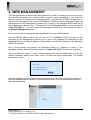
4. WEB MANAGEMENT ..................................................................................................... 70
4.1 Information ................................................................................................................. 71
4.1.1 System Information.............................................................................................. 72
4.1.2 User Authentication.............................................................................................. 73
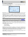
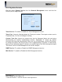
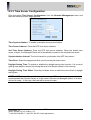
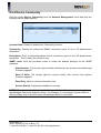
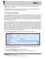
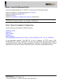
4.2 Network Management ................................................................................................ 74
4.2.1 Network Configuration ......................................................................................... 75
4.2.2 System Service.................................................................................................... 76
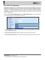
4.2.3 Time Server Configuration ................................................................................... 77
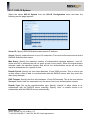
4.2.4 Device Community............................................................................................... 78
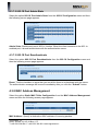
4.2.5 Trap Destination................................................................................................... 79
4.2.6 Trap Configuration ............................................................................................... 79
4.3 Switch Management................................................................................................... 80
4.3.1 Switch Configuration............................................................................................ 81
4.3.2 Port Configuration................................................................................................ 81
4.3.3 Port Mirroring ....................................................................................................... 82
4.3.4 DSCP Remark ..................................................................................................... 82
4.3.5 Static Multicast Configuration............................................................................... 83
4.3.6 Rapid Spanning Tree ........................................................................................... 84
4.3.6.1 RSTP Switch Settings ................................................................................... 85
4.3.6.2 RSTP Physical Port Settings......................................................................... 86
4.3.7 802.1X Configuration ........................................................................................... 87
4.3.7.1 802.1X System.............................................................................................. 88
4.3.7.2 802.1X Port Admin State ............................................................................... 89
4.3.7.3 802.1X Port Reauthenticate .......................................................................... 89
4.3.8 MAC Address Management ................................................................................. 89
4.3.9 VLAN Configuration ............................................................................................. 90
4.3.9.1 802.1q Tag VLAN .......................................................................................... 91
4.3.9.2 802.1q Tag VLAN Member ............................................................................ 93
4.3.9.3 802.1q Service VLAN Member...................................................................... 93
4.3.9.4 802.1q Protocol VLAN................................................................................... 94
4.3.9.5 Management VLAN....................................................................................... 94
4.3.9.6 Port-based VLAN .......................................................................................... 95
4.3.10 QoS Priority ....................................................................................................... 95
4.3.10.1 QoS Port Configuration ............................................................................... 96
4.3.10.2 QoS Mapping Configuration ........................................................................ 97
4.3.10.3 Rate Limiters ............................................................................................... 97
4.3.11 IGMP Snooping.................................................................................................. 98
4.3.11.1 IGMP Configuration ..................................................................................... 99
4.3.11.2 IGMP VLAN ID .......................................................................................... 100
4.3.11.3 IPMC Segment .......................................................................................... 100
4.3.11.4 IPMC Profile .............................................................................................. 101
4.3.11.5 IGMP Filtering............................................................................................ 102
4.3.12 MVR Configuration .......................................................................................... 102
4.3.12.1 MVR Settings ............................................................................................ 104
4.3.12.2 MVR Group ............................................................................................... 105
4.3.13 Security Configuration ..................................................................................... 105
3
SIGNAMAX a.s.
Office: Vlarska 22, 627 00 Brno, CZ
T:+420 533 338 854 l F:+420 533 338 883 l www.signamax.eu
4.3.13.1 DHCP Opt82 Settings ............................................................................... 106
4.3.13.2 DHCP Port Settings................................................................................... 107
4.3.13.3 Filter Configuration.................................................................................... 108
4.3.13.4 Configuring DHCP Snooping..................................................................... 110
4.3.13.5 Static IP Table Configuration ......................................................................111
4.3.13.6 Storm Control .............................................................................................111
4.3.13.7 Anti-broadcast Control............................................................................... 112
4.3.14 Access Control List Management .................................................................... 112
4.3.14.1 ACL Rate Limiter Configuration ................................................................. 113
4.3.14.2 ACL Configuration ..................................................................................... 113
4.4 Switch Monitor.......................................................................................................... 118
4.4.1 Switch Port State ............................................................................................... 119
4.4.2 Anti-broadcast Status......................................................................................... 120
4.4.3 DHCP Snooping ................................................................................................ 120
4.4.4 MAC Address Table ........................................................................................... 121
4.4.5 Port Counters..................................................................................................... 121
4.4.5.1 Port Traffic Statistics.................................................................................... 122
4.4.5.2 Port Packet Error Statistics.......................................................................... 122
4.4.5.3 Port Packet Analysis Statistics .................................................................... 124
4.4.6 RSTP Monitor .................................................................................................... 125
4.4.6.1 RSTP VLAN Bridge Overview ..................................................................... 125
4.4.6.2 RSTP Port Status ........................................................................................ 126
4.4.7 IGMP Monitor..................................................................................................... 127
4.4.7.1 IGMP Snooping Status ................................................................................ 127
4.4.7.2 IGMP Group Table....................................................................................... 128
4.4.8 SFP Information................................................................................................. 128
4.4.8.1 SFP Port Info............................................................................................... 129
4.4.8.2 SFP Port State ............................................................................................ 129
4.4.9 802.1X Monitor .................................................................................................. 130
4.5 System Utility............................................................................................................ 130
4.5.1 Upgrade............................................................................................................. 131
4.5.2 Backup / Restore ............................................................................................... 131
4.5.3 Factory Default .................................................................................................. 133
4.6 Save Configuration................................................................................................... 133
4.7 Reset System ........................................................................................................... 133
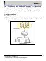
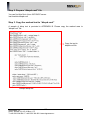
APPENDIX A: Set Up DHCP Auto-Provisioning ............................................................ 134
APPENDIX B: DHCP Text Sample .................................................................................. 139
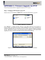
APPENDIX C: Firmware Upgrade via TFTP ................................................................... 141
4
SIGNAMAX a.s.
Office: Vlarska 22, 627 00 Brno, CZ
T:+420 533 338 854 l F:+420 533 338 883 l www.signamax.eu
1. INTRODUCTION
Thank you for using the 24 10/100Mbps ports plus 2 or 4 uplink combo ports Managed
Switch that is specifically designed for SMB (small and medium businesses) and FTTB
applications. The Managed Switch provides a built-in management module that enables
users to configure and monitor the operational status both locally and remotely. This User’s
Manual will explain how to use command-line interface and Web Management to configure
your Managed Switch. The readers of this manual should have knowledge about their
network typologies and about basic networking concepts so as to make the best of this
user’s manual and maximize the Managed Switch’s performance for your personalized
networking environment.
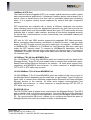
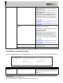
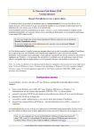
1.1 Switch Front and Rear Panel
500-7624FE2GC
Front Panel: 24-PORT 10/100Mbps
Rear Panel: 2 UPLINK COMBO PORTS
5
SIGNAMAX a.s.
Office: Vlarska 22, 627 00 Brno, CZ
T:+420 533 338 854 l F:+420 533 338 883 l www.signamax.eu
1.2 Management Software & Interfaces
Management options available for this Managed Switch are listed below:
•
•
•
Local Console Management
Telnet Management
SNMP Management
Console Program
The Managed switch has a built-in Command Line Interface (CLI) that allows you to
configure the system, monitor the status, and reset the system. You can use this CLI as
your only management system. However, another network management option, SNMPbased management system, is also available.
You can access the text-mode Console Program locally by connecting a VT100 terminal or
a workstation running VT100 emulation software to the Managed switch RS-232 DB-9
console port directly. Telnet can also be used to login and access the CLI through network
connection remotely.
SNMP Management System
Standard SNMP-based network management system provides users a way to manage the
Managed switch through the network remotely. When you use a SNMP-based network
management system, the Managed switch becomes one of the managed devices (network
elements) in that system. The Managed Switch management module contains an SNMP
agent that will respond to the requests from the SNMP-based network management system.
These requests, which you can control, can vary from getting system information to setting
the device attribute values.
The Managed Switch’s private MIB is provided for installation into your SNMP-based
network management system.
1.3 Management Preparations
After you have decided how to manage your Managed Switch, you are required to connect
cables properly, determine the Managed switch IP address and, in some cases, install MIB
shipped with your Managed switch.
Connecting the Managed Switch
It is very important that the proper cables with the correct pin arrangement are used when
connecting the Managed Switch to other switches, hubs, workstations, etc.
6
SIGNAMAX a.s.
Office: Vlarska 22, 627 00 Brno, CZ
T:+420 533 338 854 l F:+420 533 338 883 l www.signamax.eu
1000Base-X SFP Port
The small form-factor pluggable (SFP) is a compact optical transceiver used in optical
data communications applications. It interfaces a network device mother board (for a
switch, router or similar device) to a fiber optic or unshielded twisted pair networking
cable. It is a popular industry format supported by several fiber-optic component
vendors.
SFP transceivers are available with a variety of different transmitter and receiver
types, allowing users to select the appropriate transceiver for each link to provide the
required optical reach over the available optical fiber type. SFP transceivers are also
available with a “copper” cable interface, providing a host device designed primarily
for optical fiber communications to also communicate over unshielded twisted pair
networking cable.
SFP slot for 3.3V mini GBIC module supports hot swappable SFP fiber transceiver.
Before connecting other switches, workstation or Media Converter, make sure both
sides of the SFP transfer are with the same media type, for example: 1000Base-SX
to 1000Base-SX, 1000Bas-LX to 1000Base-LX. And check the fiber-optic cable type
match the SFP transfer model. To connect to 1000Base-SX transceiver, use the
multi-mode fiber cable that one side is male duplex LC connector type. To connect to
1000Base-LX transfer, use the single-mode fiber cable that one side is male duplex
LC connector type.
10/100Base-T RJ-45 Auto-MDI/MDIX Port
24 x 10/100Base-T RJ-45 Auto-MDI/MDIX ports are located at the front panel of the
Managed Switch. These RJ-45 ports enable users to connect their traditional copperbased Ethernet/Fast Ethernet devices to the network. All these ports support autonegotiation and MDI/MDIX auto-crossover, i.e. either crossover or straight-through
CAT-5 UTP or STP cable may be used.
10/100/1000Base-T RJ-45 Auto-MDI/MDIX Port
10/100/1000Base-T RJ-45 Auto-MDI/MDIX ports are located at the front or back of
the Managed Switch depending on the model that you purchased. These RJ-45 ports
allow users to connect their traditional copper-based Ethernet/Fast Ethernet/Gigabit
Ethernet devices to the network. All these ports support auto-negotiation and
MDI/MDIX auto-crossover, i.e. either crossover or straight through CAT-5E UTP or
STP cable may be used.
RS-232 DB-9 Port
The RS-232 DB-9 port is located at the rear panel of the Managed Switch. This DB-9
port is used for local, out-of-band management. Since this DB-9 port of the Managed
Switch is DTE, a null modem is also required to connect the Managed Switch and the
PC. By connecting this DB-9 port, it allows you to configure and check the status of
Managed Switch even when the network is down or disconnected.
7
SIGNAMAX a.s.
Office: Vlarska 22, 627 00 Brno, CZ
T:+420 533 338 854 l F:+420 533 338 883 l www.signamax.eu
RJ-45 DB-9 Port
The RJ-45 DB-9 port is located on the front panel of the Managed Switch. This RJ-45
DB-9 port is used for local, out-of-band management. This DB-9 port is DTE;
therefore, a null modem is required to connect the Managed Switch and the PC. With
a connection through RJ-45 DB-9 port, users can configure and check the Managed
Switch even when the network is down.
MIB for Network Management Systems
Private MIB (Management Information Bases) must be installed before you manage the
Switch through the SNMP-based network management system. The MIB file with the file
name extension “.mib” is shipped together with the Managed switch. If this file is not
provided with the Switch, please contact your sales representative.
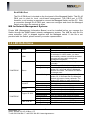
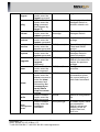
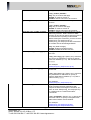
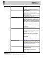
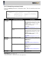
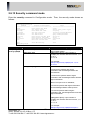
1.4 LED Definitions
Model
7624FE2GC
LED
Power
Color
Off
Green
Green
COM
Green
Orange
Orange blinking
7624FE2GC
Status
Green blinking
Link/ACT
Speed
Copper 25 & 26
7624FE2GC
Fiber 25 & 26
Off
Green
Green blinking
Off
Green
off
Green
Green blinking
Orange
Orange blinking
Orange
Orange blinking
Description
Power is off.
Power is on.
Out-of-band management via Console port
is activated. In other words, you have
successfully entered a terminal emulation
program and are ready to begin the
management session.
The Managed Switch is operating
normally.
The Managed Switch is booting up.
Insert a pin or paper clip to push the Reset
button for 3 seconds then the Managed
Switch will restart. The Status LED blinks
in orange once.
Insert a pin or paper clip to push the Reset
button for 10 seconds then the Managed
Switch will reset to factory defaults. The
Status LED blinks in green three times.
There is no connection.
The link is up.
The LED blinks when traffic is present.
The port link speed is in 10Mbps.
The port link speed is in 100Mbps.
The port link speed is in 10 Mbps.
The port link speed is in 100Mbps.
The LED blinks when traffic is present.
The port link speed is in 1000Mbps.
The LED blinks when traffic is present.
The port link speed is in 1000Mbps.
The LED blinks when traffic is present.
8
SIGNAMAX a.s.
Office: Vlarska 22, 627 00 Brno, CZ
T:+420 533 338 854 l F:+420 533 338 883 l www.signamax.eu
9
SIGNAMAX a.s.
Office: Vlarska 22, 627 00 Brno, CZ
T:+420 533 338 854 l F:+420 533 338 883 l www.signamax.eu
2. COMMAND LINE INTEFACE (CLI)
This chapter introduces you how to use Managed Switch CLI, specifically in:
•
•
•
•
Local Console
Telnet
Configuring the system
Resetting the system
2.1 Using the Local Console
Local Console is always done through the RS-232 DB-9 or RJ45 DB-9 port and requires a
direct connection between the switch and a PC. This type of management is very useful
especially when the network is down and the switch cannot be reached by any other means.
You also need to use the Local Console Management to setup the Switch network
configuration for the first time. You can setup the IP address and change the default
configuration to desired setting to enable Telnet or SNMP services.
Follow these steps to begin a management session using Local Console Management:
Step 1: Attach the serial cable to the RS-232 DB-9 or RJ-45 DB-9 port.
Step 2: Attach the other end to the serial port of a PC or workstation.
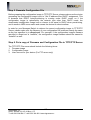
Step 3: Run a terminal emulation program using the following settings:
•
•
•
•
•
•
•
Emulation
BPS
Data bits
Parity
Stop bits
Flow Control
Enable
VT-100/ANSI compatible
9600
8
None
1
None
Terminal keys
Step 4: Press Enter to access the CLI (Command Line Interface) mode.
10
SIGNAMAX a.s.
Office: Vlarska 22, 627 00 Brno, CZ
T:+420 533 338 854 l F:+420 533 338 883 l www.signamax.eu
2.2 Remote Console Management - Telnet
You can manage the Managed Switch via a Telnet session. However, you must first assign
a unique IP address to the Switch before doing so. Use the Local Console to login the
Managed Switch and assign the IP address for the first time.
Follow these steps to manage the Managed Switch through Telnet session:
Step 1: Use Local Console to set up the assigned IP parameters of the Managed Switch,
•
•
•
IP address
Subnet Mask
Default gateway IP address, if required
Step 2: Run Telnet.
Step 3: Log into the Switch CLI mode.
Limitations: When using Telnet, keep the following in mind:
Only two active Telnet sessions can access the Managed Switch at the same time.
2.3 Navigating CLI
The Command Line Interface (CLI) of this Managed Switch is divided into three different
modes. After you enter the required username and password, you start from the User mode.
The commands available depend on which mode you are currently in. Enter a question mark
(?) at the system prompt to obtain a list of commands available for each command mode.
When you successfully access the Switch, you begin in Root directory. Enter your username
and password, and then you will be directed to User mode. In CLI management, the User
mode only provides users basic functions to operate the Managed Switch. If you would like
to use advanced features of the Managed Switch, such as, VLAN, QoS, Rate limit control,
you must enter the Enable or Configuration mode. The following table provides an overview
of this Managed Switch.
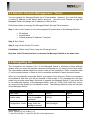
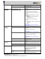
Command Mode
User mode
Access Method
Log in
From user mode,
enter the enable
command
From the enable
Configuration mode mode, enter the
config command
Enable mode
Prompt
Exit Method
SWH>
logout
SWH#
exit
SWH(config)#
exit
11
SIGNAMAX a.s.
Office: Vlarska 22, 627 00 Brno, CZ
T:+420 533 338 854 l F:+420 533 338 883 l www.signamax.eu
NOTE: By default, the model name will be used for the prompt display. You can change
the prompt display to the one that is ideal for your network environment using the
hostname command (introduced in System Command Mode). However, for convenience,
the prompt display “SWH” will be used consistently throughout this user’s manual.
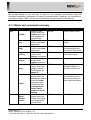
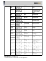
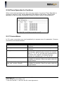
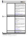
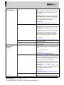
2.3.1 Mode and command summary
Mode
User
Command
enable
exit
help
history
logout
ping
show
Enable
Enter
Enable
mode
Access Method
While in User
mode, enter the
enable command
and a password
(press Enter).
While in User
mode, enter exit
command.
While in User
mode, enter help
command.
While in User
mode, enter
history command.
While in User
mode, enter
logout command.
While in User
mode, enter the
ping command
and followed by
target IP.
While in User
mode, enter the
show command or
enter the show
command and
followed by the
command you
would like to
view its current
setting.
While in User
mode, enter the
enable command
and a password
(press Enter).
Prompt
SWH#
Description
Enter Enable mode.
Username:
Exit from current
mode.
SWH>
Show available
commands that can
be used in User mode.
List commands that
have been used.
SWH>
Username:
Logout
SWH>
The ping test from the
Managed Switch to
another network unit.
SWH>
Show a list of
commands or show
the current setting of
each listed command.
SWH#
Enter Enable mode.
12
SIGNAMAX a.s.
Office: Vlarska 22, 627 00 Brno, CZ
T:+420 533 338 854 l F:+420 533 338 883 l www.signamax.eu
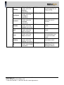
backup
configure
console
disable
exit
help
history
ip
While in Enable
mode, enter the
backup
command.
While in Enable
mode, enter the
configure
command.
While in Enable
mode, enter the
console
command.
While in Enable
mode, enter the
disable command.
While in Enable
mode, enter the
exit command.
While in Enable
mode, enter the
help command.
While in Enable
mode, enter the
history command.
While in Enable
mode, enter the ip
command.
SWH(backup)#
Backup a copy of
configuration file via
FTP or TFTP.
SWH(config)#
Enter Config mode.
SWH(console)#
Set up time-out timer
when the user is
inactive.
SWH>
Exit from current
mode.
SWH>
Exit from current
mode.
SWH#
Show available
commands that can
be used in Enable
mode.
List commands that
have been used.
SWH#
SWH(ip)#
13
SIGNAMAX a.s.
Office: Vlarska 22, 627 00 Brno, CZ
T:+420 533 338 854 l F:+420 533 338 883 l www.signamax.eu
Configure IP
addresses of the
Managed Switch.
logout
ping
reboot
restore
service
system
upgrade
user
show
write
Enter
Configuration
mode
While in Enable
mode, enter the
logout command.
While in Enable
mode, enter the
ping command
and followed by
target IP.
While in Enable
mode, enter the
reboot command.
While in Enable
mode, enter the
restore command.
While in Enable
mode, enter the
service command.
While in Enable
mode, enter the
system command.
While in Enable
mode, enter the
upgrade
command.
While in Enable
mode, enter the
user command.
While in Enable
mode, enter the
show command or
enter the show
command and
followed by the
command you
would like to
view its current
setting.
While in Enable
mode, enter the
write command.
While in Enable
mode, enter the
configure
command.
Username:
Logout
SWH#
The ping test from the
Managed Switch to
another network unit.
Boot-up
message
To restart the
Managed Switch.
SWH#
Load factory default
settings.
SWH(service)#
To enable or disable
Telnet and SNMP
service.
Configure the
Managed Switch’s
basic information.
Upgrade the Managed
Switch’s firmware and
restore the previous
settings.
Configure user
accounts.
SWH(system)#
SWH(upgrade)#
SWH(user)#
SWH#
Show a list of
commands or show
the current setting of
each listed command.
SWH#
Save the configuration
file.
SWH(config)#
In Enable mode, users
can access the
Switch’s advanced
features, such as
VLAN, Rate limit,
QoS, etc.
14
SIGNAMAX a.s.
Office: Vlarska 22, 627 00 Brno, CZ
T:+420 533 338 854 l F:+420 533 338 883 l www.signamax.eu
Configuration
exit
help
When in Config
mode, enter the
exit command.
When in Config
mode, enter the
help command.
When in Config
mode, enter the
acl command.
When in Config
dot.1x
mode, enter the
dot1x command.
When in Config
history
mode, enter the
history command.
When in Config
mode, enter the
igmpfilter
igmpfilter
command.
When in Config
igmp
mode, enter the
igmp command.
When in Config
mac
mode, enter the
mac command.
When in Config
mirror
mode, enter the
mirror command.
When in Config
mode, enter the
multicast
multicast
command.
When in Config
mvr
mode, enter the
mvr command.
When in Config
port
mode, enter the
port command.
When in Config
qos
mode, enter the
qos command.
When in Config
remarking mode, enter the
qos command.
When in Config
stp
mode, enter the
stp command.
acl
SWH#
Exit from current
mode
SWH(config)#
SWH(configacl)#
Show available
commands that can
be used in Config
mode.
Set up ACL rules and
configurations.
SWH(configdot1x)#
Set up RADIUS
configurations.
SWH(config)#
List commands that
have been used.
SWH(configigmpfilter)#
Configure IGMP
filtering functions.
SWH(configigmp)#
Configure IGMP
settings.
SWH(configmac)#
Set up a static MAC
table.
SWH(configmirror)#
Set up target port for
mirroring.
SWH(configmulticast)#
Set up multicasting
groups.
SWH(configmvr)#
Configure Multicast
VLAN Registration
(MVR) settings.
Configure the status of
each port.
SWH(config)#
SWH(configqos)#
SWH(configremarking)#
Set up the priority of
packets within the
Managed Switch.
Set up queue and
DSCP mappings.
SWH(configstp)#
Set up each port’s
STP status.
15
SIGNAMAX a.s.
Office: Vlarska 22, 627 00 Brno, CZ
T:+420 533 338 854 l F:+420 533 338 883 l www.signamax.eu
security
switch
vlan
show
When in Config
mode, enter the
security
command.
When in Config
mode, enter the
switch command.
When in Config
mode, enter the
vlan command.
When in Config
mode, enter the
show command or
enter the show
command and
followed by the
command you
would like to view
its current
setting.
SWH(configsecurity)#
SWH(configswitch)#
SWH(configvlan)#
SWH(config)#
Configure Option82,
Storm Control and
Anti-broadcasting
settings.
Set up the max-frame.
Set up VLAN mode
and VLAN
configuration.
Show a list of
commands or show
the current setting of
each listed command.
2.3.2 Quick keys
Using the key…
Enter the “?” commands
Enter incomplete characters then
enter the question mark (?)
Press the direction or key
Enter unique part of a command and
press TAB key
Ctrl + A
Ctrl + B
Ctrl + D
Ctrl + E
Ctrl + H
Ctrl + I
Ctrl + K
Ctrl + L
Ctrl + M
Ctrl + N
Ctrl + P
Ctrl + U
Ctrl + W
To do this…
Obtain a list of available commands in the current
mode.
List all commands similar to incomplete characters.
Scroll through the command history.
The switch will automatically display the full
command.
Move to the start of line.
Move the cursor to the space on the left.
Logout.
Move to the end of line.
Clear the preceding character.
The same function as the TAB key.
Clear all characters starting from the cursor.
Re-enter the same command line.
Enter
Display history commands.
Display history commands.
Clear all characters.
Clear characters before the cursor.
16
SIGNAMAX a.s.
Office: Vlarska 22, 627 00 Brno, CZ
T:+420 533 338 854 l F:+420 533 338 883 l www.signamax.eu
2.3.3 General Commands
This section introduces you some general commands that you can use in User, Enable, and
Config mode, including “help”, “exit”, “history”, “logout”, and “show”.
Entering the command…
Enter the “help” command
Enter the “exit” command
Enter the “history” command
Enter the “logout” command
Enter the “show” command
To do this…
Obtain a list of available commands in the current
mode.
Return to the former mode or login screen.
List all commands that have been entered.
Logout from the CLI. (“logout” can not be used in
Configuration mode.)
Show system information.
Show available commands.
Show a command’s current settings.
Show currently-configured settings.
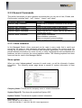
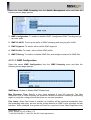
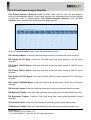
2.3.3.1 Show command
In this Managed Switch, show command can be used in every mode that is useful and
convenient for users to view displayed information without leaving the current mode. By
issuing the combination of show command and adequate parameters, show command can
provide different information for users not only to verify configurations and troubleshoot the
problems, but also to monitor the current operation status. The following explains how show
command can be used in this Managed Switch.
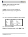
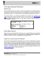
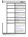
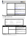
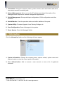
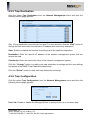
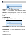
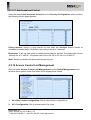
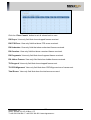
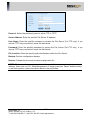
Show system
When you enter “show system” command in each mode, you will be informed of system
information. The following screen page shows a sample of system information in User
mode.
Company Name: This shows the company name or related information.
System Object ID: This shows the predefined System OID.
System Contact: This shows the system contact information.
17
SIGNAMAX a.s.
Office: Vlarska 22, 627 00 Brno, CZ
T:+420 533 338 854 l F:+420 533 338 883 l www.signamax.eu
System Name: This shows the system name or related descriptions.
System Location: This shows the system location.
Model Name: This shows the product model name.
Firmware Version: This shows the current firmware version of this Managed Switch.
Serial Number: This shows the serial number of this Managed Switch.
M/B Version: This shows the motherboard version of this Managed Switch.
Date Code: This shows the date code of this Managed Switch.
Up Time: This shows how long this Managed Switch has been turned on since the last
reboot.
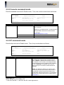
Show available commands
In User, Enable and Configuration mode, you can type “show” to view a list of commands
available.
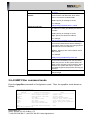
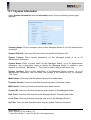
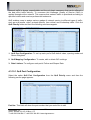
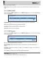
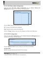
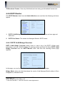
Show a Command’s Current Settings
In User, Enable and Configuration mode, you can type “show” and followed by the command
listed above to view its current setting. For example, if you type “show qos” in Enable
mode (SWH#), then the current setting of qos command will be displayed.
18
SIGNAMAX a.s.
Office: Vlarska 22, 627 00 Brno, CZ
T:+420 533 338 854 l F:+420 533 338 883 l www.signamax.eu
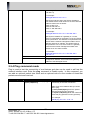
Within QoS, the rate limit configurations can be set. You can type “show qos rate limit” in
any mode to view its current setting.
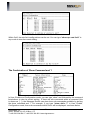
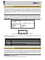
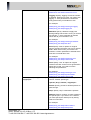
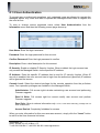
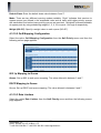
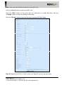
The Combination of Show Command and ?
In User, Enable and Configuration mode, you can type “show” and followed by the command
listed above to view its current setting. If there are sub-commands within a command (this
is shown as […]), the Managed Switch can also show sub-commands available by issuing
the show command and ?. For example, if you type “show dot1x ?” in User, Enable,
Configuration mode, then sub-commands within Dot1x will be displayed as shown below.
19
SIGNAMAX a.s.
Office: Vlarska 22, 627 00 Brno, CZ
T:+420 533 338 854 l F:+420 533 338 883 l www.signamax.eu
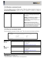
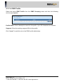
Type in the sub-command after “show dot1x” to view its current configurations. For
example, if you issue “show dot1x sys” command, the following screen page appears.
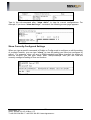
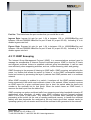
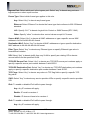
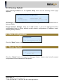
Show Currently-Configured Settings
When you type a specific command in Enable or Config mode to configure or edit the setting
of a certain function, you can type “show” to view the setting you have just configured or
edited. For example, when you are in SWH(console)# and have changed the setting of
time-out function, you can type “show” after “SWH(console)#” then you can view the
currently-configured setting of time-out function.
20
SIGNAMAX a.s.
Office: Vlarska 22, 627 00 Brno, CZ
T:+420 533 338 854 l F:+420 533 338 883 l www.signamax.eu
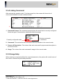
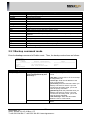
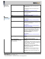
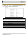
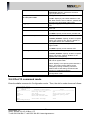
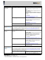
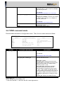
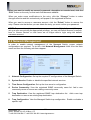
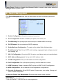
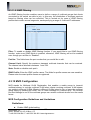
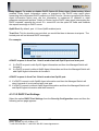
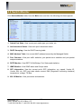
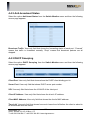
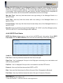
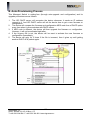
2.3.4 Listing Command
After entering the question mark (?) at the prompt line, the screen will show a list of
commands available for each command mode.
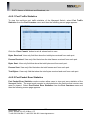
2-
3-
4-
1-
1. Command Prompt: The command prompt shows the mode that is currently configured.
Users can type in commands or characters after the prompt.
Currently configured mode
Entering commands
or characters
2. Command: This column lists all commands that are available in the current mode.
3. Purpose & Description: This column lists each command’s purpose and description in
the current mode.
4. Usage: This column lists each command’s usage in the current mode.
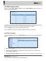
2.3.5 Usage Help
When entering a command without the required parameter, the system will remind users of
the correct command’s syntax and parameter.
21
SIGNAMAX a.s.
Office: Vlarska 22, 627 00 Brno, CZ
T:+420 533 338 854 l F:+420 533 338 883 l www.signamax.eu
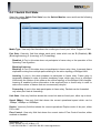
2.3.6 Press Spacebar to Continue
When a command generates more than one page outputs, the prompt “Press Spacebar to
continue or any key to exit!” will be displayed at the bottom of the screen. Simply press
spacebar to view next page information or press any key to return to the prompt line.
2.3.7 Conventions
In CLI, some conventions are used consistently to express uses of a parameter. Common
conventions are described below.
Conventions
<
>
[
]
<port_list>
<enable | disable>
<administrator | read_and_write |
read_only | access_denied>
Descriptions
Required parameters or values are in angle
brackets.
Optional parameters or values are in square
brackets.
“port_list” allows you to enter several discontinuous
port number, separating by a comma, for example,
port “5, 7, 9, 12”; or, you can enter continuous port
numbers with a hyphen and separating by a
comma, for example, port “1-5, 7-9, 12-15.”
Two options, separated by a vertical bar, are
available for selection. Select one option within the
angle bracket.
Several options, separated by a vertical bar, are
available for selection. Select one option within the
angle bracket.
22
SIGNAMAX a.s.
Office: Vlarska 22, 627 00 Brno, CZ
T:+420 533 338 854 l F:+420 533 338 883 l www.signamax.eu
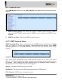
2.3.8 Login Username & Password
Default Login
When the Managed Switch is turned on, the boot-up message will be displayed first and
then followed by username and password prompt. The default login username is admin and
no password is required for default setting, thus press Enter key in password prompt. When
system prompt shows “>”, it means that the user has successfully entered the User mode.
For security reasons, it is strongly recommended that you add a new username and
password using User command in Enable mode for security reasons (See User command
mode for detailed descriptions). When you create your own login username and password
with administrator operation privilege, you can delete the default username (admin) to
prevent unauthorized access.
Boot-up message
Enable Mode Password
Enable mode is password-protected. When you try to enter Enable mode, a password
prompt will appear to request the user to provide the legitimate password. Enable mode
password is the same as the one entered after login password prompt. By default, no
password is required. Therefore, press Enter key in password prompt.
Forget Your Login Username & Password?
If you forget your login username and password, you can use the “reset button” on the front
panel to set all configurations back to factory defaults. Once you have performed system
reset to defaults, you can login with default username and password. Please note that if you
use this method to gain access to the Managed Switch, all configurations saved in Flash will
be lost. It is strongly recommended that a copy of configurations is backup in your local
hard-drive or file server from time to time so that previously-configured settings can be
reloaded to the Managed Switch for use when you gain access again to the device (See
Backup command mode for detailed descriptions).
23
SIGNAMAX a.s.
Office: Vlarska 22, 627 00 Brno, CZ
T:+420 533 338 854 l F:+420 533 338 883 l www.signamax.eu
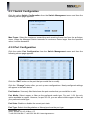
2.4 User Mode
When the Managed Switch is turned on, the boot-up message will be displayed first and
then followed by username and password prompt. The default login username is admin and
no password is required for default setting, thus press Enter key in password prompt. When
system prompt shows “SWH>”, it means that the user has successfully entered the User
mode.
NOTE: It is strongly recommended that you add a new username account and password
using User command in Enable mode or change the default password for security reasons.
When you create a new login username and password with administrator operation
privilege, you can delete the default username (admin) account to prevent or restrict
unauthorized access.
Boot-up message
Default username: admin and without the password
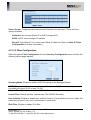
In “SWH>”, enter the question mark (?) to show all commands available for User mode. The
screen shows as follows:
Command
enable
exit
help
history
logout
ping
show
Purpose
Enter the Enable mode.
Quit the User mode.
Display a list of available commands in User mode.
Display a list of commands that have been entered.
Logout from the Managed Switch.
Allow users to ping a specified network device.
Show a list of commands or show the current setting of each listed command.
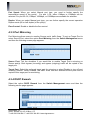
2.5 Enable Mode
The only place where you can enter Enable mode is in User mode. Enter the enable
command after the prompt “SWH>” and enter your login password (By default, there is no
password required.). When you successfully enter Enable mode, the prompt will be changed
to “SWH#”. Press ? to view a list of commands available for use.
24
SIGNAMAX a.s.
Office: Vlarska 22, 627 00 Brno, CZ
T:+420 533 338 854 l F:+420 533 338 883 l www.signamax.eu
Command
backup
configure
console
disable
exit
help
history
ip
logout
ping
reboot
restore
service
system
time-server
upgrade
user
write
Description
Backup a copy of configuration file via FTP or TFTP.
Enter Configuration mode.
Set up time-out time.
Exit Enable mode and return to User Mode.
Exit Enable mode and return to User Mode.
Display a list of available commands in Enable mode.
Show a list of commands that have been entered.
Assign the IP addresses manually.
Logout from the Managed Switch.
Allow users to ping a specified network device.
Restart the Managed Switch.
Load the default factory settings or load the default factory settings but keep IP
address.
Enable or disable Telnet and SNMP service.
Configure system information.
Configure NTP time server settings.
Upgrade firmware and restore previous settings via TFTP or FTP.
Set up a user account and its access privilege.
Save running configurations to Flash.
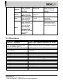
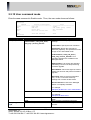
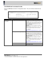
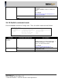
2.5.1 Backup command mode
Enter the backup command in Enable mode. Then, the backup mode shows as follows:
SWH#backup
SWH(backup)#
Command
===================
config
exit
SWH(backup)#
Prompt
SWH(backup)#
Purpose & Description
===========================
Set Configuration
Exit from current mode
Usage
=============================
config
exit
Command & Parameter
config <ftp | tftp> <server ip>
[username][password] <file
directory>
exit
Description
To backup a configuration file via FTP or
TFTP.
<ftp | tftp>: Choose FTP or TFTP to backup
a configuration file.
<server ip>: Enter the IP address of the
FTP or TFTP server.
[username]: Enter the username when you
backup a file via FTP server. If you use
TFTP server to backup a file, you do not
need to specify username.
[password]: Enter the password when you
backup a file via FTP server. If you use
TFTP server to backup a file, you do not
need to specify password.
<file directory>: Enter the file location
within the FTP or TFTP server.
Exit the current mode and return to Enable
Mode.
25
SIGNAMAX a.s.
Office: Vlarska 22, 627 00 Brno, CZ
T:+420 533 338 854 l F:+420 533 338 883 l www.signamax.eu
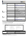
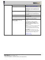
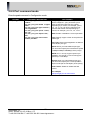
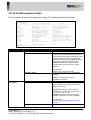
2.5.2 Console command mode
Enter the console command in Enable mode. Then, the console mode shows as follows:
SWH# console
SWH(console)#
Command
===================
time-out
exit
show
SWH(console)#
Prompt
SWH(console)#
Purpose & Description
===========================
Set Time Out
Exit from current mode
Usage
=============================
time-out <secs>
exit
Show Console Settings
show
Command &Parameter
time-out <secs>
Description
To disconnect the Managed Switch when the
user is inactive.
<secs>: 0 or 5-9999 seconds. “0” means that the
Managed Switch will never be disconnected.
For example:
SWH(console)# time-out 300
Exit the current mode and return to Enable Mode.
Show time-out setting.
exit
show
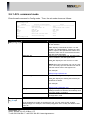
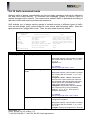
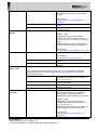
2.5.3 IP command mode
Enter the ip command in Enable mode. Then, the ip mode shows as follows:
SWH# ip
SWH(ip)#
Command
===================
type
address
exit
show
SWH(ip)#
Prompt
SWH (ip)#
Purpose & Description
===========================
Set Type
Set IP Address
Exit from current mode
Usage
=============================
type <manual|dhcp>
address <ip> <mask> <gw>
exit
Show IP Settings
show
Command & Parameter
type <manual | dhcp>
address <ip> <mask> <gw>
Description
Specify whether the IP address is manually assigned
or automatically assigned from the DCHP server.
When “DHCP” is specified and a DHCP server is
also available on the network, the Managed Switch
will automatically get the IP address from the DHCP
server. If “Static IP” is selected, users need to
further specify the IP address, Subnet Mask and
Gateway.
NOTE: This Managed Switch also supports autoprovisioning function that enables DHCP clients to
automatically download the latest Firmware and
configuration image from the server. For information
about how to set up a DHCP server, please refer to
APPENDIX A.
Enter the IP address, subnet mask and gateway of
26
SIGNAMAX a.s.
Office: Vlarska 22, 627 00 Brno, CZ
T:+420 533 338 854 l F:+420 533 338 883 l www.signamax.eu
this Managed Switch. (Default IP address is
192.168.0.1)
For example:
SWH(ip)# address 192.110.1.2
Specify the subnet mask to the Switch IP address.
The default subnet mask values for the three Internet
address classes are as follows:
Class A: 255.0.0.0
Class B: 255.255.0.0
Class C: 255.255.255.0
For example:
SWH(ip)# address 192.110.1.2 255.255.255.0
Specify the IP address of a gateway or a router,
which is responsible for the delivery of the IP packets
sent by the Switch. This address is required when the
Switch and the network management station are on
different networks or subnets. The default value of
this parameter is 0.0.0.0, which means no gateway
exists and the network management station and
Switch are on the same network.
For example:
SWH(ip)# address 192.110.1.2 255.255.255.0
120.110.1.5
Exit the current mode and return to Enable Mode.
Show permanent MAC address and currentlyconfigured IP address, subnet mask and gateway
address of this Managed Switch.
exit
show
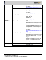
2.5.4 Ping command mode
Ping is used to test the connectivity of end devices and also can be used to self test the
network interface card. Enter the ping command in Enable mode. In this command, you
can add an optional packet size value and an optional value for the number of times that
packets are sent and received.
Prompt
SWH#
Command & Parameter
ping <ip> [-s size (8-4000)bytes] [-r
repeat (1-99)times]
Description
“Ping” function enables the user to test the
connectivity of the other end device.
<ip>: Enter the IP address that you would
like to ping.
[-s size (8-4000)bytes]: Enter the packet
size that would be sent (optional).
[-r repeat (1-99)times]: Enter the number of
times that ping packets are sent (optional).
For example:
SWH# ping 127.0.0.1 –s 50 –r 5
27
SIGNAMAX a.s.
Office: Vlarska 22, 627 00 Brno, CZ
T:+420 533 338 854 l F:+420 533 338 883 l www.signamax.eu
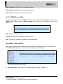
2.5.5 Restore command mode
Enter the restore command in Enable mode. When the restore command is issued, you
can load the default factory settings but keep the assigned IP address by adding the
optional “keep-ip” parameter.
Prompt
SWH#
Command & Parameter
restore <default> [keep-ip]
Description
Load the default factory settings. When restoring
is in process, the Managed Switch will reboot
automatically.
<default>: Load default factory settings.
[keep-ip]: Load default factory settings but keep
the IP address. You can still access the
Managed Switch remotely by using the same IP
address (optional).
NOTE: There are three ways to set the
Managed Switch back to the factory default
settings. Users can use the restore command in
CLI, user Web Management or simply press the
“Reset” button located on the front panel to
restore the device back to the initial state.
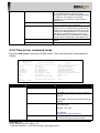
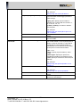
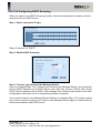
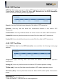
2.5.6 Service command mode
Enter the service command in Enable mode. Then, the service mode shows as follows:
SWH# service
SWH(service)#
Command
===================
telnet
snmp
web
exit
SWH(service)#
Prompt
SWH(servicetelnet)#
SWH(servicesnmp)#
Purpose & Description
===========================
Set Telnet
Set SNMP
Set Web
Exit from current mode
Usage
=============================
telnet
snmp
web
exit
Command & Parameter
mode < enable | disable>
exit
show
mode < enable | disable>
exit
show
Description
To enable or disable Telnet service on the
Managed Switch.
For example:
SWH(service-telnet)# mode enable
Quit the Telnet service mode.
Show Telnet service information.
To enable or disable SNMP service on the
Managed Switch.
For example:
SWH(service-snmp)# mode enable
Quit the SNMP service mode and return to the
service mode.
Show SNMP service information.
28
SIGNAMAX a.s.
Office: Vlarska 22, 627 00 Brno, CZ
T:+420 533 338 854 l F:+420 533 338 883 l www.signamax.eu
SWH(snmpcommunity)#
add<community>
Add a new community in SNMP. The name of
the community is limited to 20 alphanumeric
characters long.
<community>: Enter the community name.
delete<community>
SWH(snmpcommunity_com
munity name)#
exit
show
state <enable | disable>
description <description>
ip <enable | disable>
ip_addr <ip_addr>
level <administrator |
read_and_write | read_only |
access_denied>
For example:
SWH(snmp-community)# add myswitch
To delete a community that is already added to
the Managed switch.
For example:
SWH(snmp-community)# delete myswitch
Quit SNMP service mode.
Show SNMP service information.
To enable or disable this community.
For example:
SWH(snmp-community_community name)#
state enable
Enter a unique description for this community
name of up to 35 alphanumeric characters. This
is used for reference only.
For example:
SWH(snmp-community_community name)#
description rdcommunity
To enable or disable IP security. If enabled, the
community may access the Managed Switch
only through the management station, which has
the exact IP address specified in IP address
field below. If disabled, the community can
access the Managed Switch through any
management stations.
For example:
SWH(snmp-community_community name)# ip
enable
Specify the IP address used for IP Security
function.
<ip_addr>: Enter the IP address.
Specify the desired privilege for the SNMP
operation.
<administrator | read_and_write | read_only |
access_denied>: Four operation privileges are
available in the Managed Switch.
Administrator: Full access right includes
maintaining user account & system information,
loading factory settings, etc.
Read & Write: Full access right but cannot
modify user account and upgrade Firmware.
Read Only: Allow to retrieve information only.
Access Denied: Access to the Managed Switch
29
SIGNAMAX a.s.
Office: Vlarska 22, 627 00 Brno, CZ
T:+420 533 338 854 l F:+420 533 338 883 l www.signamax.eu
is completely forbidden.
NOTE 1: When the community browses the
Managed Switch without proper access right,
the Managed Switch will respond nothing. For
example, if a community only has Read & Write
privilege, then it cannot browse the Managed
Switch’s user table.
NOTE 2: If you would like to edit the settings of
your new account, you can enter the command
community community name under the
SWH(service-snmp)#.
For example:
If you want to edit settings of the account
“admin”, you can use the following commands to
enter the editing mode.
exit
SWH(snmp-trapdest)#
show
add <trap_id> <trap_ip>
<community>
SWH# service
SWH(service)# snmp
SWH(service-snmp)# community admin
SWH(snmp-community_admin)#
Quit the Community mode and return to SNMP
service mode.
Show detailed information of this community.
To add a new trap destination. This function will
send traps to the specified destination.
<trap_id>: 1~10
<trap_ip>: The specific IP address of the
network management system that will receive
the trap.
<community>: Enter the community name of
up to 20 characters.
For example:
SWH(snmp-trap-dest)# add 1 192.168.1.113
trapcommu1
NOTE: If you would like to edit the settings of a
trap destination, you can enter the command
trap-dest trap id under the SWH(servicesnmp)#.
For example:
If you want to edit settings of the trap destination
“2”, you can use the following commands to
enter the editing mode.
delete <trap_id>
exit
SWH# service
SWH(service)# snmp
SWH(service-snmp)# trap-dest 2
SWH(snmp-trap-dest_2)#
To delete a registered trap destination.
SWH(snmp-trap-dest)# delete 1
Quit the Trap Destination mode and return to
SNMP service mode.
30
SIGNAMAX a.s.
Office: Vlarska 22, 627 00 Brno, CZ
T:+420 533 338 854 l F:+420 533 338 883 l www.signamax.eu
SWH(snmp-trapdest_trap id)#
show
state <enable | disable>
Show each trap’s (1~10) detailed settings.
To enable or disable this trap destination.
destination <ip_addr>
For example:
SWH(snmp-trap-dest_trap id)# state enable
Specify the IP address of this trap destination.
community<community>
<ip_addr>: Enter the trap destination IP
address.
Enter the community name.
exit
show
SWH(snmp-trapmode)#
port-link <enable | disable>
power-down <enable | disable>
all <enable | disable>
exit
SWH(serviceweb)#
show
mode < enable | disable>
<community>: Enter the community name of
up to 20 characters.
Quit the Trap ID mode and return to SNMP
service mode.
Show this Trap’s state, destination, and
community information.
To enable or disable the Managed Switch to
send port Link Up or Link Down trap.
To enable or disable the Managed Switch to
send port power-down trap.
To set up all functions above to enabled or
disabled. When “enabled” is set, a trap notice
will be sent when a certain situation occurs.
Quit the Trap mode and return to SNMP service
mode.
Show Trap mode information.
To enable or disable Web service on the
Managed Switch.
For example:
SWH(service-web)# mode enable
Quit the Web service mode and return to the
service mode.
Show Web service information.
exit
show
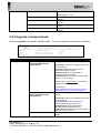
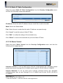
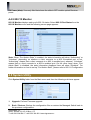
2.5.7 System command mode
Enter the system command in Enable mode. Then, the system mode shows as follows:
SWH# system
SWH(system)#
Command
===================
company
syscontact
sysname
syslocation
hostname
exit
show
SWH(system)#
Prompt
SWH(system)#
Purpose & Description
===========================
Set Company Name
Set System Contact
Set System Name
Set System Location
Set System Host Name
Exit from current mode
Usage
=============================
company <name>
syscontact <contact>
sysname <name>
syslocation <location>
syshostname <hostname>
exit
Show System Settings
show
Command & Parameter
company <company_name>
syscontact <system_contact>
Description
Specify a company name of up to 55
alphanumeric characters.
Enter contact information for this Managed
Switch of up to 55 alphanumeric characters.
31
SIGNAMAX a.s.
Office: Vlarska 22, 627 00 Brno, CZ
T:+420 533 338 854 l F:+420 533 338 883 l www.signamax.eu
sysname <system_name>
syslocation<system_location>
hostname
exit
show
Enter a unique name for this Managed Switch of
up to 55 alphanumeric characters. Use a
descriptive name to identify the Managed Switch
in relation to your network, for example,
“Backbone 1”. This name is mainly used for
reference only.
Enter a unique location for the Managed Switch
of up to 55 alphanumeric characters.
Enter a new hostname prompt for this Managed
Switch of up to 15 alphanumeric characters. By
default, the hostname prompt shows the model
name of this Managed Switch. You can change
the factory-assigned hostname prompt to the
one that is easy for you to identify (e.g. location)
during network configuration and maintenance.
Quit the current mode and return to Enable
Mode.
Show current system information settings.
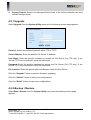
2.5.8 Time-server command mode
Enter the time-server command in Enable mode. Then, the time-server mode shows as
follows:
SWH# time-server
SWH(time-server)#
Command
===================
mode
ip-addr
2nd-addr
syninterval
time-zone
day-saving
offset
exit
show
SWH(time-server)#
Prompt
SWH(time-server)#
Purpose & Description
===========================
Set Mode
Set IP Addr
Set 2nd Addr
Set Syn-Interval
Set Time Zone
Set Daylight Saving
Set Offset
Exit from current mode
Usage
=============================
mode <enable|disable>
ip-addr <ip_addr>
2nd-addr <2nd_addr>
syninterval <hour>
time-zone <time_zone>
day-saving <enable|disable>
offset <hour>
exit
Show Time Server Settings
show
Command &Parameter
Description
mode <enable | disable>
ip-addr <ip_addr>
Enable or disable NTP time server function.
Specify the first NTP time server IP address.
2nd-addr <2nd_addr>
<ip_addr>: Enter the time server IP address.
Specify the second NTP time server IP
address.
syninterval <hour>
<2nd_addr>: Enter the second time server IP
address.
Specify the interval time to synchronize from
NTP time server.
<hour>: 1~24 hours
time-zone <time_zone>
For example:
SWH(time-server)# syninterval 2
Specify the appropriate time zone from the list.
To view the list, type in time-zone after
32
SIGNAMAX a.s.
Office: Vlarska 22, 627 00 Brno, CZ
T:+420 533 338 854 l F:+420 533 338 883 l www.signamax.eu
SWH(time-server)# and press enter.
<time_zone>: 1~146
To enable or disable the daylight saving time
function.
To offset 1 hour or 2 hours for daylight saving
function.
Quit the current mode and return to Enable
mode.
Show currently-configured time server
settings.
day-saving <enable | disable>
offset <hour>
exit
show
2.5.9 Upgrade command mode
Enter the upgrade command in Enable mode. Then, the upgrade mode shows as follows:
SWH# upgrade
SWH(upgrade)#
Command
===================
firmware
config
exit
SWH(upgrade)#
Prompt
SWH(upgrade)#
Purpose & Description
===========================
Upgrade Firmware
Upgrade Configuration
Exit from current mode
Usage
=============================
firmware
config
exit
Command & Parameter
firmware <ftp|tftp> <serverip>
[username] [password]
<filelocation>
Description
To upgrade Firmware via FTP or TFTP.
<serverip>: Enter the IP address of the FTP
or TFTP server.
[username]: Enter the username for
Firmware upgrade via FTP.
[password]: Enter the password for
Firmware upgrade via FTP.
<filelocation>: Enter the file location within
the FTP or TFTP server.
Please refer to APPENDIX C for Firmware
upgrade via TFTP server.
config <ftp|tftp> <serverip>
[username] [password]
<filelocation>
exit
For example:
SWH(upgrade)# firmware tftp 192.168.0.15
SWH2126_FW_1.01.00_20100105.bin
To upgrade a configuration file via FTP or
TFTP.
<serverip>: Enter the IP address of the FTP
or TFTP server.
[username]: Enter the username for
configuration file upgrade via FTP.
[password]: Enter the password for
configuration file upgrade via FTP.
<filelocation>: Enter the file location within
the FTP or TFTP server.
Quit the current mode and return to Enable
Mode.
33
SIGNAMAX a.s.
Office: Vlarska 22, 627 00 Brno, CZ
T:+420 533 338 854 l F:+420 533 338 883 l www.signamax.eu
2.5.10 User command mode
Enter the user command in Enable mode. Then, the user mode shows as follows:
SWH# user
SWH(user)#
Command
===================
<name>
add
delete
exit
show
SWH(user)#
Prompt
SWH(user)#
Purpose & Description
===========================
Edit User
Add User
Delete User
Exit from current mode
Usage
=============================
<name>
add <name> [pass] <level>
del <username>
exit
Show User Settings
show
Command & Parameter
add <username> [password]
<administrator | read_and_write |
read_only | access_denied>
Description
Add a new user and specify its access
privilege.
<username>: Specify the new username.
[password]: Specify this username’s
password (optional). This password is used
to login to CLI and Enable mode.
<administrator | read_and_write |
read_only | access_denied>: Four
operation privileges are available in the
Managed Switch.
Administrator: Full access right includes
maintaining user account and performing
Firmware upgrade.
Read & Write: Full access right but cannot
modify user account and perform Firmware
upgrade.
Read Only: Allow to retrieve information
only. In CLI, a user with “read only”
privilege can not enter enable mode.
Access Denied: Access to the Managed
Switch is completely forbidden.
delete <username>
exit
SWH(user_userna
me)#
show
state <enable | disable>
For example:
SWH(user)# add user1 user1 administrator
Delete a registered user.
For example:
SWH(user)# delete user1
Quit the current mode and return to Enable
Mode.
Show currently-registered usernames.
To enable or disable this new login user
account.
34
SIGNAMAX a.s.
Office: Vlarska 22, 627 00 Brno, CZ
T:+420 533 338 854 l F:+420 533 338 883 l www.signamax.eu
password<password>
For example:
SWH(user_username)# state enable
Set up a password for this user account.
description <description>
<password>: Enter the password for this
user account of up to 20 alphanumerical
characters.
Enter the description for this user account.
ip <enable | disable>
ip_addr <ip_addr>
level <administrator |
read_and_write | read_only |
access_denied>
<description>: Enter the description for this
user account of up to 35 alphanumerical
characters.
To enable or disable IP security function of
this user account.
Enter the IP address for IP security function.
<ip_addr>: Enter the IP address.
Set up the console level for this user
account.
<administrator | read_and_write |
read_only | access_denied>: Four
operation privileges are available in the
Managed Switch.
NOTE: If you would like to edit the settings
of a user account, you can enter the
command user user id under the SWH#.
For example:
If you want to edit settings of the user
account “mis2”, you can use the following
commands to enter the editing mode.
SWH#user mis2
SWH(user_mis2)#
35
SIGNAMAX a.s.
Office: Vlarska 22, 627 00 Brno, CZ
T:+420 533 338 854 l F:+420 533 338 883 l www.signamax.eu
2.6 Configuration Mode
In Configuration mode, you can set up advanced switching functions, such as QoS, VLAN,
Remarking. Enter the configure (or config for short) command after SWH# directory and
type in “?” to view a list of available commands in Config mode.
SWH(config)#
Command
===================
acl
exit
help
history
dot1x
igmpfilter
igmp
mac
mirror
mvr
multicast
port
qos
remarking
stp
security
switch
vlan
Purpose & Description
===========================
Enter ACL Cmd. Mode
Exit from current mode
Show available commands
Show history commands
Enter Dot1x Cmd. Mode
Enter IGMP Filter Cmd. Mode
Enter IGMP Cmd. Mode
Enter MAC Cmd. Mode
Enter Mirror Cmd. Mode
Enter MVR Cmd. Mode
Enter Multicast Cmd. Mode
Set Port Cmd.
Enter QoS Cmd. Mode
Enter Remarking Cmd. Mode
Enter STP Cmd. Mode
Enter Security Cmd. Mode
Enter Switch Cmd. Mode
Enter VLAN Cmd. Mode
Usage
=============================
acl
exit
help
history
dot1x
igmpfilter
igmp
mac
mirror
mvr <vid>
multicast
port <all|port_list>
qos
remarking
stp
security
switch
vlan
show
SWH(config)#
Show current settings
show <...>
Command
acl
dot1x
exit
help
history
igmp
igmpfilter
mac
mirror
multicast
mvr
port
qos
remarking
stp
vlan
security
switch
show
Description
Set up ACL configurations.
Set up RADIUS configurations.
Exit the config mode.
Display a list of available commands in Configuration mode.
Show commands that have been used.
Set up IGMP settings.
Set up IGMP filtering settings.
Set up static MAC table.
Set up target port for mirroring.
Set up multicast groups.
Configure Multicast VLAN Registration (MVR) settings.
Configure the status of each port.
Set up the priority of packets within the Managed Switch.
Set up queue and DSCP mappings.
Set up each port’s STP status.
Set up VLAN mode and VLAN configuration.
Configure Option 82, storm control, and anti-broadcasting settings.
Set up the max-frame size.
Show a list of commands or show the current setting of each listed command.
36
SIGNAMAX a.s.
Office: Vlarska 22, 627 00 Brno, CZ
T:+420 533 338 854 l F:+420 533 338 883 l www.signamax.eu
2.6.1 ACL command mode
Enter the acl command in Config mode. Then, the acl mode shows as follows:
SWH(config)# acl
SWH(config-acl)#
Command
===================
<id>
rate-lim-id
add
delete
apply
exit
show
SWH(config-acl)#
Prompt
SWH(config-acl)#
Purpose & Description
===========================
Edit ACL ID
Set Rate Limit ID
Add ACL
Delete ACL
Apply ACL
Exit from current mode
Usage
=============================
<id>
rate-lim-id <id> <rate>
add <id>
del <id>
apply
exit
Show ACL settings
show
Command & Parameter
rate-lim-id <id> <rate>
add <acl_id>
Description
Specify the rate of traffic that is sent or received
on the interface.
<id>: Specify a rate limiter ID from 1 to 128.
<rate>: 16-1000000(Kbps). Traffic that is less
than or equal to the specified rate will be sent;
whereas, traffic sent or received that exceeds
the rate will be discarded.
Add an ACL configuration rule. 300 ACL rules
can be created in this Managed Switch.
<acl_id>: Specify an ACL ID from 1 to 300.
NOTE: Each ACL ID number can only be used
once. The lookup process will start from the ID
with the lowest value to the highest one.
For example:
delete <acl_id>
SWH(config-acl)# add 100
Delete an existing ACL configuration rule.
<acl_id>: Specify an existing ACL ID that you
would like to delete.
For example:
SWH(config-acl)# delete 100
Apply currently-configured ACL settings. The
settings will become effective immediately when
you issue “apply” command.
exit
Quit the current mode and return to
Configuration mode.
show
Show ACL or rate limiting configurations.
Edit details of an ACL configuration rule.
apply
SWH(configacl_acl id)#
If you would like to modify an existing ACL rule, you can enter acl ACL ID after
SWH(config)#. For example, enter SWH(config)# acl 100 to modify the details of ACL
100 rule.
in-port <any | 1-26>
Set up which port is the ingress port.
37
SIGNAMAX a.s.
Office: Vlarska 22, 627 00 Brno, CZ
T:+420 533 338 854 l F:+420 533 338 883 l www.signamax.eu
or in-port<any | 1-28>
<any | 1-26>: Specify “any” to denote any ports
are ingress ports or specify a port number.
For example:
frame-type <any | ethernet | llc |
other>
SWH(config-acl_100)# in-port any
Set up which frame type applies to this rule.
<any | ethernet | llc | other>: Four frame types
are available for selection.
Any: Specify “any” to denote any frame types.
Ethernet: Specify “ethernet” to denote the
frame type that conforms to 802.3 Ethernet
standard.
LLC: Specify “llc” to denote Logical Link Control
or SNAP frames (RFC 1042).
Other: Specify “other” to denote other control
values except LLC frames.
source-mac <any |
xx:xx:xx:xx:xx:xx>
Set up which source MAC address applies to
this rule.
<any | xx:xx:xx:xx:xx:xx>: Specify “any” to
denote all MAC addresses or type a specific
source MAC address in AA:AA:AA:AA:AA:AA
format.
dest-mac <any |
xx:xx:xx:xx:xx:xx>
For example:
SWH(config-acl_100)# source-mac any
Set up which destination MAC address should
apply to the rule.
<any | xx:xx:xx:xx:xx:xx>: Specify “any” to
denote all MAC addresses or type a specific
destination MAC address in
AA:AA:AA:AA:AA:AA format.
ether-type <any | 0000-FFFF>
For example:
SWH(config-acl_100)# dest-mac any
Configure the Ethernet type.
<any | 0000-FFFF>: Specify “any” to denote
any Ethernet type or specify Ethernet type value
in hexadecimal notation.
vid <any | 1-4094>
For example:
SWH(config-acl_100)# ether-type 0800
Configure traffic from which VLAN resides in.
<any | 1-4094>: Specify “any” to denote traffic
from any VLAN or specify an existing VID to
denote source traffic from this specified VLAN.
ipv4 <any | enable | disable>
For example:
SWH(config-acl_100)# vid 200
To enable or disable IPv4 traffic to pass
38
SIGNAMAX a.s.
Office: Vlarska 22, 627 00 Brno, CZ
T:+420 533 338 854 l F:+420 533 338 883 l www.signamax.eu
through.
ipv6 <any | enable | disable>
ipv6-mld <any | enable | disable>
source-ip <any | x.x.x.x/y.y.y.y>
<any | enable | disable>:
Any: Any IP versions will apply.
Enable: IP must be version 4.
Disable: IP does not have to be version 4.
To enable or disable IPv6 traffic to pass
through.
<any | enable | disable>:
Any: Any IP versions will apply.
Enable: IP must be version 6.
Disable: IP does not have to be version 6.
Enable or disable IPv6 MLD (Multicast Listener
Discovery) function. MLD is similar to IGMP
function in IPv4 and is used to discover ports on
a VLAN that are requesting multicast data.
Before issuing this command, you have to issue
SWH(config_acl-100)# ipv6 any or
SWH(config_acl-100)# ipv6 enable commands
to activate IPv6 in this Managed Switch.
Any: Any MLD will apply.
Enable: Enable IPv6 MLD function.
Disable: Disable IPv6 MLD function.
Configure which source IP address applies to
this rule.
<any | x.x.x.x/y.y.y.y>: Specify “any” to denote
any source IP addresses or specify a specific
source IP address (x.x.x.x) with a subnet mask
(y.y.y.y).
dest-ip <any | x.x.x.x/y.y.y.y>
For example:
SWH(config-acl_100)# source-ip any
Configure which destination IP address applies
to this rule.
<any | x.x.x.x/y.y.y.y>: Specify “any” to denote
any destination IP addresses or specify a
specific destination IP address (x.x.x.x) with a
subnet mask (y.y.y.y).
flowlabel <any | 0-1048575>
For example:
SWH(config-acl_100)# dest-ip any
Specify a flow label to traffic. This is used in
IPv6 to handle real-time applications with
sequences. Before issuing this command, you
have to issue “SWH(config_acl-100)# ipv6 any”
or “SWH(config_acl-100)# ipv6 enable”
commands.
<any | 0-1048575>: Specify “any” to denote any
flow label values or specify a designated flow
label value between 0 and 1048575.
For example:
SWH(config_acl-100)# ipv6 enable
SWH(config_acl-100)# flowlabel any
39
SIGNAMAX a.s.
Office: Vlarska 22, 627 00 Brno, CZ
T:+420 533 338 854 l F:+420 533 338 883 l www.signamax.eu
protocol <any | 0-255>
Specify the IP protocol to be used.
tos <any | 0-255>
<any | 0-255>: Specify “any” denote any
protocols or specify the type of transport
packets used e.g. 1=ICMP, 6=TCP, 17=UDP.
Specify TOS (Type of Service) priority level.
source-port <any | 0-65535>
<any | 0-255>: Specify “any” to denote any
priority levels or specify a priority level between
0 and 255.
Configure the source port number that applies
to this rule.
<any | 0-65535>: Specify “any” to denote any
source port numbers or specify a specific
source port number between 0 and 65535.
dest-port <any | 0-65535>
For example:
SWH(config-acl_100)# source-port 80
Configure the destination port number that
applies to this rule.
<any | 0-65535>: Specify “any” to denote any
destination port numbers or specify a specific
destination port number between 0 and 65535.
tcpflag <any | 0-255>
service-vid <any | 1-4094>
permit-type <forward | mirror |
logging | ratelimit | svid | cvid>
For example:
SWH(config-acl_100)# dest-port 80
Specify TCP Flag values.
<any | 0-255>: Specify “any” to denote any
values in TCP flag field or specify a specific
TCP flag value.
Set up service provider VLAN ID. This is used
for double tagging.
<any | 1-4094>: Specify “any” to denote any
service provider VIDs or specify a specific
service provider VID.
Specify the action taken for this ACL rule.
<forward | mirror | logging | ratelimit | svid |
cvid>:
Forward: Specify “forward” to transfer packets.
Actions allowed for “forward” can be set by
issuing “action” parameter.
For example:
SWH(config_acl-100)# permit-type forward
SWH(config_acl-100)# action permit
Mirror: Specify “mirror” to send a copy of
packets in source ports to a target port. If you
would like to use this as permit type, you have
to set up Mirroring configurations. Please refer
to Mirror Command Mode for further
explanations.
40
SIGNAMAX a.s.
Office: Vlarska 22, 627 00 Brno, CZ
T:+420 533 338 854 l F:+420 533 338 883 l www.signamax.eu
For example:
SWH(config_acl-100)# permit-type mirror
Logging: Specify “logging” to limit the number
of packets. When this is used, you need to use
logging <1-128> parameter to indicate how
many packet size you would like to use.
For example:
SWH(config_acl-100)# permit-type logging
SWH(config_acl-100)# logging 50
Ratelimit: Specify “ratelimit” to apply rate
limiting settings. When this is used, you need to
use rate-lim <1-128> parameter to indicate
which rate ID you would like to use.
For example:
SWH(config_acl-100)# permit-type ratelimit
SWH(config_acl-100)# rate-lim 1
Svid: Specify “svid” to replace an original
service provider VID with a new one for egress
traffic. When this is used, you need to use
newsvid <1-4094> parameter to indicate which
new VID you would like to use.
For example:
SWH(config_acl-100)# permit-type svid
SWH(config_acl-100)# newsvid 200
Cvid: Specify “cvid” to replace an original
customer VID with a new one for egress traffic.
When this is used, you need to use the
following two parameters:
action <permit | drop | redirect |
copytocpu>
For example:
SWH(config_acl-100)# permit-type cvid
SWH(config_acl-100)# repcvid enable
SWH(config_acl-100)# newcvid 300
Configure which action is taken when you
choose “forward” permit type.
<permit | drop | redirect | copytocpu>:
Permit: Specify “permit” to allow all packets to
pass through.
Drop: Specify “drop” to discard the packets.
Redirect: Specify “redirect” to route packets to
the specific port. If you want to use “redirect”,
you have specify the redirect port by issuing
redir-port command.
For example:
SWH(config_acl-100)# action redirect
SWH(config_acl-100)# redir-port 24
41
SIGNAMAX a.s.
Office: Vlarska 22, 627 00 Brno, CZ
T:+420 533 338 854 l F:+420 533 338 883 l www.signamax.eu
redir-port <1-26>
or redir-port <1-28>
Copytocpu: Specify “copytocpu” to send a
copy of packets to CPU.
Configure which port is the redirect port.
newsvid <1-4094>
<1-26>: Specify a port number between 1 and
26. When action is set to “redirect”, packets will
be sent to the designated redirect port.
Specify a logging ID that applies to this ACL
rule.
Specify the rate limiting ID that applies to this
ACL rule.
Specify a new service provider VID.
repcvid <enable | disable>
<1-4094>: Specify a new service provider VID.
Specify to replace the customer VID or not.
logging <1-128>
rate-lim <1-128>
newcvid <1-4094>
reass-queue <enable | disable>
new-queue <0-7>
<enable | disable>: Specify “enable” to replace
with a new customer VID. Specify “disable” to
not replace with a new customer VID.
Specify a customer VID to replace old one in
egress traffic.
<1-4094>: Specify a new customer VID.
Replace the customer priority or not.
<enable | disable>: Specify “enable” to replace
with a new priority. Specify “disable” to not
replace with a new priority.
Specify a customer priority queue to replace an
old one for egress traffic.
<0-7>: Specify a new priority queue between 0
and 7. The priority queue setting can be
changed by issuing remarking command.
Please refer to Remarking command mode
section for detailed descriptions.
Quite the current mode and return to ACL
Configuration mode.
Show or verify the ACL rule that you configure.
exit
show
2.6.2 Dot.1X command mode
Enter the dot1x command in Configuration mode. Then, the dot1x mode shows as follows:
SWH(config)# dot1x
SWH(config-dot1x)#
Command
===================
sys
state
authentic
exit
show
SWH(config-dot1x)#
Purpose & Description
===========================
Enter Sys Cmd. Mode
Set State
Reset Authenticate
Exit from current mode
Usage
=============================
sys
state <port_list> <type>
authentic <port_list>
exit
Show Dot1x Settings
show
42
SIGNAMAX a.s.
Office: Vlarska 22, 627 00 Brno, CZ
T:+420 533 338 854 l F:+420 533 338 883 l www.signamax.eu
Prompt
SWH(configdot1x-sys)#
Command & Parameter
server <ip_addr>
secret <shared_secret>
maxquery <1-16>
Description
Specify IP address for an external RADIUS
authentication server.
<ip_addr>: Specify RADIUS Authentication
server IP address.
The identification word or number assigned to
each RADIUS authentication server with which
the client shares a secret. Notice that the
Managed Switch and authentication server must
have the same secret.
<shared_secret>: Specify a shared secret of up
to 30 alphanumerical characters.
Specify the maximum number of authentication
attempts between 1 and 16. Users who fail to
authenticate will not grant access to the switch.
When the authentication attempts reach the
specified number and all fail, the authentication
server will not allow users to authenticate for a
period of time.
<1-16>: Specify the maximum numbers of
authentication attempts between 1 and 16.
For example:
type <port_list> <manual | auto>
SWH(config-dot1x-sys)# maxquery 5
Set up the reauthentication type.
<port_list>: Specify a port number or multiple
port numbers with the format 5, 7, 8, 9, 12 or
5, 7-9, 12.
<manual | auto>: Specify “manual” to allow
clients to re-authenticate with the RADIUS
server manually. Specify “auto” to enable clients
to re-authenticate with the RADIUS server
automatically.
period <reauth_period>
eap-timeout <eapol_timeout>
exit
show
For example:
SWH(config-dot1x-sys)# type 1-4,10-15,18,19
auto
Set up how often a client should re-authenticate
with the RADIUS server. This is used to set up
how often a client is able to re-authenticate with
the RADIUS server after they use up the
maximum authentication attempts.
<reauth_period>: 10-3600 seconds
The time that the Managed Switch waits for
responses from the server host to an
authentication request.
<eapol_timeout>: 10~255 seconds
Quit the current mode and return to SWH
(config-dot1x)#.
Show or verify current dot.1X configurations.
43
SIGNAMAX a.s.
Office: Vlarska 22, 627 00 Brno, CZ
T:+420 533 338 854 l F:+420 533 338 883 l www.signamax.eu
SWH(configdot1x)#
state <port_list> <disable |
enable>
Enable or disable ports’ Dot.1X authentication.
When clients connect to these Dot.1X-enabled
ports, they will be prompted with username and
password.
<port_list>: Specify a port number or multiple
port numbers with the format 5, 7, 8, 9, 12 or
5, 7-9, 12.
authentic <port_list>
For example:
SWH(config-dot1x)# state 1-4,10-15,18,19
enable
This will send out authentication message to the
selected clients immediately.
<port_list>: Specify a port number or multiple
port numbers with the format 5, 7, 8, 9, 12 or
5, 7-9, 12.
For example:
SWH(config-dot1x)# authentic 1-4,10-15,18,19
Quit the current mode and return to
Configuration mode
Show or verify each port’s current dot.1x status.
exit
show
2.6.3 IGMP command mode
Enter the igmp command in Configuration mode. Then, the igmp mode shows as follows:
SWH(config)# igmp
SWH(config-igmp)#
Command
===================
mode
router-port
flooding
vlanstate
vlanserver
maxresponse
fast-leave
exit
show
SWH(config-igmp)#
Prompt
SWH(config-igmp)#
Purpose & Description
===========================
Set Mode
Set Router Port
Set Flooding
Set VLAN State
Set VLAN Server
Set MAX Response Time
Set Fast Leave
Exit from current mode
Usage
=============================
mode <enable|disable>
router-port <port_list>
Show IGMP Settings
show
vlanstate <vid> <type>
vlanserver <vid> <ip>
maxresponse <time>
fast-leave <enable|disable>
exit
Command & Parameter
mode <enable | disable>
router-port <port_list>
Description
To enable or disable IGMP function. If you
would like to use IGMP filtering function, you
must enable IGMP first; otherwise, IGMP
filtering will not be activated even though you
issue “mode enable” command after
SWH(config-igmpfilter)#.
To configure which ports belong to multicast
router ports.
<port_list>: Specify a port number or multiple
port numbers with the format 5, 7, 8, 9, 12 or
5, 7-9, 12.
For example:
44
SIGNAMAX a.s.
Office: Vlarska 22, 627 00 Brno, CZ
T:+420 533 338 854 l F:+420 533 338 883 l www.signamax.eu
vlanstate <vid> <enable |
disable>
SWH(config-igmp)# router-port 1-4,1015,18,19
When enabled, the port in VLAN will monitor
network traffic and determine which hosts
want to receive the multicast traffic.
<vid>: Specify an existing VLAN ID.
vlanserver<vid><ip>
For example:
SWH(config-igmp)#vlanstate 1 enable
Assign a multicast IP address statically. This
IP address is usually provided by the service
provider.
<vid>: Specify an existing VLAN ID.
<ip>: Specify a multicast IP address.
maxresponse<time>
For example:
SWH(config-igmp)#vlanserver 1 224.0.3.10
The Max Response Time is used to specify
the maximum allowed time before sending a
responding report to notify the routing protocol
that there are no more members.
<time>: Specify a time value between 0 and
255 seconds.
fast-leave <enable | disable>
exit
show
For example:
SWH(config-igmp)#maxresponse 100
When Fast Leave is enabled, an interface will
be removed immediately from the forwarding
table entry as soon as the system detects an
IGMP Leave message on that interface. When
disabled, the system will wait for a period of
time (Max Response time) before removing an
interface.
Quit the current mode and return to
SWH(config)#
Show current IGMP settings.
2.6.4 IGMP Filter command mode
Enter the igmpfilter command in Configuration mode. Then, the igmpfilter mode shows as
follows:
SWH(config)# igmpfilter
SWH(config-igmpfilter)#
Command
Purpose & Description
=================== ===========================
segment
Enter Segment Cmd. Mode
profile
Enter Profile Cmd. Mode
mode
Set Mode
channel
Set Channel Limit
state
Set State
filter
Set Filter Maping
exit
Exit from current mode
show
Show IGMP Filter Settings
SWH(config-igmpfilter)#
Usage
=============================
segment <id>
profile <name>
mode <enable|disable>
channel <port_list> <1-128>
state <port_list> <type>
filter <port_list> <profile>.
exit
show
45
SIGNAMAX a.s.
Office: Vlarska 22, 627 00 Brno, CZ
T:+420 533 338 854 l F:+420 533 338 883 l www.signamax.eu
Prompt
SWH(configsegment)#
Command & Parameter
add <seg_id> <seg_name> <ip>
<ip>
Description
To create a new segment.
<seg_id>: Specify a segment ID from 1 to
400.
<seg_name>: Specify a segment name of up
to 20 characters.
<ip> <ip>: Specify the multicast IP range. The
available IP range is from 224.0.1.0~238.255.
255.255
delete <seg_id>
For example:
SWH(config-segment)# add 2 myseg
224.0.1.5 235.255.255.253
To delete an existing segment.
<seg_id>: Specify the segment ID that you
would like to delete.
exit
SWH(configsegment_Seg ID)#
SWH(configprofile)#
show
Edit details of an existing segment.
For example:
SWH(config-segment)# delete 2
Quit the current mode and return to igmpfilter
configuration mode.
Show current IPMC segment settings.
If you would like to modify an existing segment, you can enter segment Seg ID after
SWH(config-igmpfilter)#. For example, enter SWH(config-igmpfilter)# segment 2 to
modify the details of the segment 2.
add <profile_name> <seg_id>
To create a new profile.
<seg_id> ...
<profile_name>: Specify a profile name of up
to 20 characters.
<seg_id>: Specify an existing segment ID.
(The field for segment ID is from the entry
registered in Segment option.)
delete <profile_name>
For Example:
SWH(config-profile)# add myprofile 2 3 4 5 6
To delete an existing profile.
<profile_name>: Specify the profile name
that you would like to delete.
exit
SWH(configsegment_profile_n
ame)#
SWH(config-
show
Edit details of an existing profile.
For Example:
SWH(config-profile)# delete myprofile
Quit the current mode and return to igmpfilter
configuration mode.
Show current IPMC profile settings.
If you would like to modify an existing profile, you can enter profile profile_name after
SWH(config-igmpfilter)#. For example, enter SWH(config-igmpfilter)# profile myprofile
to modify the details of the profile myprofile.
segment-id <seg_id> <seg_id> ..
<seg_id>: Specify segment IDs that belong to
this profile. (The field for segment ID is from
the entry registered in Segment option.)
mode <enable | disable>
To enable or disable IGMP filtering function. If
46
SIGNAMAX a.s.
Office: Vlarska 22, 627 00 Brno, CZ
T:+420 533 338 854 l F:+420 533 338 883 l www.signamax.eu
igmpfilter)#
channel <port_list> <1-128>
you would like to use IGMP filtering function,
make sure IGMP is activated; otherwise,
IGMP filtering will not be enabled even though
you issue “enable” command.
Specify the maximum transport multicast
channels that can be received.
<port_list>: Specify a port number or multiple
port numbers with the format 5, 7, 8, 9, 12 or
5, 7-9, 12.
<1-128>: Specify the channel number
between 1 and 128.
state <port_list> <enable | disable>
For example:
SWH(config-igmpfilter)# channel 1-4,1015,18,19 10
To enable or disable each port’s IGMP filtering
function.
<port_list>: Specify a port number or multiple
port numbers with the format 5, 7, 8, 9, 12 or
5, 7-9, 12.
filter <port_list> <profile_name>
<profile_name> ...
For example:
SWH(config-igmpfilter)# state 1-4, 10-15, 18,
19 enable
This allows the specified IP multicast profile
information to pass-through.
<port_list>: Specify a port number or multiple
port numbers with the format 5, 7, 8, 9, 12 or
5, 7-9, 12.
<profile_name>: Specify an existing profile
name. (The field for profile name is from the
entry registered in Profile option.)
For example:
SWH(config-igmpfilter)# filter 1-4 myprofile
Quit the current mode and return to
Configuration mode.
Show current IGMP filtering settings.
exit
show
2.6.5 MAC command mode
Enter the mac command in Configuration mode. Then, the mac mode shows as follows:
SWH(config)# mac
SWH(config-mac)#
Command
===================
static
exit
SWH(config-mac)#
Prompt
SWH(config-macstatic)#
Purpose & Description
===========================
Enter Static Cmd. Mode
Exit from current mode
Usage
=============================
static
exit
Command & Parameter
add <mac-addr> <vlan_id> <port |
filter>
Description
To forward or filter packets from a MAC
address.
47
SIGNAMAX a.s.
Office: Vlarska 22, 627 00 Brno, CZ
T:+420 533 338 854 l F:+420 533 338 883 l www.signamax.eu
<mac-addr>: Specify the MAC address that
applies to this rule.
<vlan_id>: Specify a VLAN ID (1~4094) that
this port belongs to.
<port | filter>: For 26-port Managed Switch,
enter the forwarding port number 1~26 or
specify “filter” or “27” to filter packets. For 28port Managed Switch, enter the forwarding
port number 1~28 or enter 29 to filter packets.
delete <mac-addr> <vlan_id> <port
| filter>
For example :
SWH(config-mac-static)# add xx-xx-xx-xx-xxxx 4094 24
SWH(config-mac-static)# add xx-xx-xx-xx-xxxx 4094 filter
Delete a MAC address setting from the
forwarding or filtering table.
<mac-addr>: Specify the MAC address that
you would like to delete.
<vlan_id>: 1~4094
<port | filter>: For 26-port Managed Switch,
enter the forwarding port number 1~26 or
specify “filter” or “27” to filter packets. For 28port Managed Switch, enter the forwarding
port number 1~28 or enter 29 to filter packets.
For example :
SWH(config-mac-static)# delete xx-xx-xx-xxxx-xx 4094 24
SWH(config-mac-static)# delete xx-xx-xx-xxxx-xx 4094 filter
Quit the current mode and return to
Configuration mode
Show current static settings.
exit
show
2.6.6 Mirror command mode
Enter the mirror command in Configuration mode. Then, the mirror mode shows as follows:
SWH(config)# mirror
SWH(config-mirror)#
Command
===================
port
target-port
exit
show
SWH(config-mirror)#
Prompt
SWH(configmirror)#
Purpose & Description
===========================
Set Port
Set Target Port
Exit from current mode
Usage
=============================
port <port_list>
target-port <type>
exit
Show Mirror Settings
show
Command & Parameter
port <mirror_port_list>
Description
To enable or disable Target Port’s mirroring
on Source ports. Both ingress (incoming) and
egress (outgoing) traffic will be copied to the
target port.
48
SIGNAMAX a.s.
Office: Vlarska 22, 627 00 Brno, CZ
T:+420 533 338 854 l F:+420 533 338 883 l www.signamax.eu
<mirror_port_list>: Enter a range of port
number (1~26 or 1~28) or enter “0” to disable
port mirroring function.
target-port <target_port | disable>
For example:
SWH(config-mirror)# port 1-4,10-15,18,19
Specify the preferred target port for mirroring.
<target_port | disable >: Enter a port number
(1~26 or 1~28) or specify “0” or “disable” to
turn this function off.
For example:
SWH(config-mirror)# target-port 24
Quit the current mode and return to
Configuration mode.
Show current mirror settings.
exit
show
2.6.7 MVR command mode
Enter the mvr command in Configuration mode. Then, the mvr mode shows as follows:
SWH(config)# mvr
SWH(config-mvr)#
Command
===================
<vid>
mode
add
delete
group
exit
show
SWH(config-mvr)#
Prompt
SWH(config-mvr)#
Purpose & Description
===========================
Edit MVR
Set Mode
Add MVR
Delete MVR
Enter Group Cmd. Mode
Exit from current mode
Usage
=============================
<vid>
mode <enable|disable>
add <vid> <receive> <source>
del <vid>
group
exit
Show MVR Settings
show
Command &Parameter
mode <enable | disable>
Description
To enable or disable MVR global settings.
For example:
add <vlan_id> <rec_port_list>
<sor_port_list> <server_ip>
SWH(config-mvr)# mode enable
To add a MVR VLAN ID and specify its
Receive and Source Port.
<vlan_id>: 1~4094
<rec_port_list>: Switch ports that receive
multicast data are specified as receiver ports.
Specify a port number or a range of port
numbers (1~26 or 1~28).
<sor_port_list>: Uplink ports resided in
multicast VLAN and send and reecive
multicast data are selected as source ports
(1~26 or 1~28). Please note that the source
ports specified here should be router ports as
well. Refer to IGMP command mode section
for detailed explanations on setting up router
ports.
<server_ip>: Specify the media server IP
49
SIGNAMAX a.s.
Office: Vlarska 22, 627 00 Brno, CZ
T:+420 533 338 854 l F:+420 533 338 883 l www.signamax.eu
address.
delete <vlan_id>
For example:
SWH(config-mvr)# add 4094 1-4,10-15,18,19
5-9,16,17 xxx.xxx.xxx.xxx
To delete a registered MVR VLAN ID.
<vlan_id>: 1~4094
exit
SWH(configmvr_vlan_id)#
SWH(config-mvrgroup)#
show
Edit details of an existing MVR entry.
For example:
SWH(config-mvr)# delete 4094
Quit the current mode and return to
Configuration mode.
Show current MVR VLAN information.
If you would like to modify an existing MVR entry, you can enter mvr vlan_id after
SWH(config)#. For example, enter SWH(config)# mvr 4094 to modify the details of the
MVR VLAN 102.
receiveport <rec_port_list>
<rec_port_list>: Switch ports that receive
multicast data are specified as receiver ports.
Specify a port number or a range of port
numbers (1~26 or 1~28).
sourceport <sor_port_list>
<sor_port_list>: Uplink ports resided in
multicast VLAN and send and reecive
multicast data are selected as source ports
(1~26 or 1~28). Please note that the source
ports specified here should be router ports as
well. Refer to IGMP command mode section
for detailed explanations on setting up router
ports.
serverip <ip>
<ip>: Specify the media server IP address.
exit
Quit the current mode and return to
Configuration mode.
show
Show currently-configured MVR setting.
add <vlan_id> <ip> <ip>
To add a new MVR group and specify the
multicasting channel that would belong to
MVR VLAN.
<vlan_id>: 1~4094
<ip><ip>: Specify the group range
224.0.1.0~238.255.255.255
delete <vlan_id> <ip> <ip>
For example:
SWH(config-mvr-group)# add 4094 224.0.1.0
238.255.255.255
To delete a registered MVR group.
<vlan_id>: 1~4094
<ip><ip>: Specify the group range
224.0.1.0~238.255.255.255
exit
show
For example:
SWH(config-mvr-group)# delete 4094
224.0.1.0 238.255.255.255
Quit the current mode and return to MVR
configuration mode.
Show MRV group configurations.
50
SIGNAMAX a.s.
Office: Vlarska 22, 627 00 Brno, CZ
T:+420 533 338 854 l F:+420 533 338 883 l www.signamax.eu
2.6.8 Multicast command mode
Enter the multicast command in Configuration mode. Then, the multicast mode shows as
follows:
SWH(config)# multicast
SWH(config-multicast)#
Command
Purpose & Description
=================== ===========================
add
Add Multicast
delete
Delete Multicast
exit
Exit from current mode
show
Show Multicast Settings
SWH(config-multicast)#
Prompt
SWH(configmulticast)#
Usage
=============================
add <ip_addr> <vid> <port>
del <ip_addr> <vid> <port>
exit
show
Command &Parameter
add <ip-addr> <vlan_id> <port>
Description
Assign a multicasting group statically.
<ip-addr>: Specify an IP address for this
multicast group. (The multicast IP address that
can be specified ranges from 224.0.1.0 to
238.255.255.255)
<vlan_id>: Specify an existing VLAN ID for
this entry.
<port>: Specify a port number (1~26 or 1~28)
to which multicast traffic will be forwarded.
delete <ip-addr> <vlan_id> <port>
For example:
SWH(config-multicast)# add 224.0.1.0 4094
24
Delete a multicast group.
<ip-addr>: Specify a multicast IP address for
this multicast group. (The multicast IP address
that can be specified ranges from 224.0.1.0 to
238.255.255.255)
<vlan_id>: Specify an existing VLAN ID for
this entry.
<port>: Specify a port number (1~26 or 1~28)
to which multicast traffic will be forwarded.
exit
show
For example:
SWH(config-multicast)# delete 224.0.1.0 4094
24
Quit the current mode and return to
Configuration mode.
Show current multicast settings.
51
SIGNAMAX a.s.
Office: Vlarska 22, 627 00 Brno, CZ
T:+420 533 338 854 l F:+420 533 338 883 l www.signamax.eu
2.6.9 Port command mode
Enter the port command in Configuration mode.
Prompt
SWH(config)#
Command &Parameter
port <all | port_list> state <enable |
disable>
port <all | port_list> media <copper
| fiber>
port <all | port_list> type <manual |
auto-negotiation>
port <all | port_list> speed <1000 |
100 | 10>
port <all | port_list> duplex <full |
half>
port <all | port_list> flow-control
<enable | disable>
Description
<all | port_list>: “all” means that port 1 to 26
will be configured. “port_list” allows you to
enter several discontinuous port number,
separating by a comma, for example, “port 5,
7, 9, 12”; or, you can enter continuous port
numbers with a dash and separating by a
comma, for example, “port 1-5, 7-9, 12-15.”
State: Enable or disable the current port state.
Type: Specify copper or fiber as the preferred
media type.
Port Type: Select Auto-Negotiation or Manual
mode as the port type.
Speed: When you select Manual port type,
you can further specify the transmission speed
(10Mbps/100Mbps/1000Mbps) of the port(s).
NOTE: Port 1~24 only support speed up to
100Mbps. Port 25~26 or Port 25~28 support
speed up to 1000 Mbps.
Duplex: When you select Manual port type,
you can further specify the current operation
Duplex mode (full or half duplex) of the port(s).
Flow Control: Enable or disable the flow
control.
For example:
SWH(config)# port all state enable
52
SIGNAMAX a.s.
Office: Vlarska 22, 627 00 Brno, CZ
T:+420 533 338 854 l F:+420 533 338 883 l www.signamax.eu
2.6.10 QoS command mode
Network traffic is always unpredictable and the only basic assurance that can be offered is
the best effort traffic delivery. To overcome this challenge, Quality of Service (QoS) is
applied throughout the network. This ensures that network traffic is prioritized according to
specified criteria and receives preferential treatments.
QoS enables you to assign various grades of network service to different types of traffic,
such as multi-media, video, protocol-specific, time critical, and file-backup traffic. Enter the
qos command in Configuration mode. Then, the qos mode shows as follows:
SWH(config)# qos
SWH(config-qos)#
Command
===================
class
mode
weight
pri-map
dscp-map
rate-limit
exit
show
SWH(config-qos)#
Prompt
SWH(config-qos)#
Purpose & Description
===========================
Set Default Class
Set Mode
Set Weight
Set 802.1p to Queue
Set DSCP to Queue
Enter Rate Limit Cmd. Mode
Exit from current mode
Usage
=============================
class <port_list> <queue>
mode <port_list> <type>
weight <port_list> <weight>
pri-map <pri_list> <queue>
dscp-map <dscp_list> <queue>
rate-limit
exit
Show QoS Settings
show
Command & Parameter
class <port_list> <queue>
Description
Configure the default class for each port.
<port_list>: Specify a port number or multiple
port numbers with the format 5, 7, 8, 9, 12 or
5, 7-9, 12.
<queue>: 0~7
mode <port_list> <weighted |
strict>
For example:
SWH(config-qos)# class 1-5,10 4
To specify “strict” or “weighted” to ports.
<port_list>: Specify a port number or multiple
port numbers with the format 5, 7, 8, 9, 12 or
5, 7-9, 12.
<weighted | strict>: “Strict” indicates that
services to the egress queues are offered in
the sequential order and all traffic with higher
priority queues are transmitted first before
lower priority queues are serviced.
“Weighted” Round-Robin shares bandwidth
at the egress ports by using scheduling
weights 1, 2, 3, 4, 5, 6, 7, 8 for queues 1
through 8 respectively.
weight <port_list> <weight>
For example:
SWH(config-qos)# mode 1-4,8,10 strict
To specify queuing weights for ports that are
configured as weighted.
<port_list>: Specify a port number or multiple
port numbers with the format 5, 7, 8, 9, 12 or
5, 7-9, 12.
<weight>: Specify the weight from 1~8 for the
53
SIGNAMAX a.s.
Office: Vlarska 22, 627 00 Brno, CZ
T:+420 533 338 854 l F:+420 533 338 883 l www.signamax.eu
queue 1 through 8 respectively.
primap <priority_list> <queue>
For example:
SWH(config-qos)# weight 2-5,10,12 1:2:4:8
To specify a priority to a queue.
<priority_list>: 0~7
<queue>: 0~7
dscpmap <dscp_list> <queue>
For example:
SWH(config-qos)# primap 1-5 2
To specify DSCP classification identification
number to a queue.
<dscp_list>: 0-63
<queue>: 0-7
SWH(config-qosrate-limit)#
ingress <port_list> <bit_rate>
SWH(config-qos)# dscpmap 1-5, 10, 13 1
To specify the ingress bit rate of the selected
ports.
<port_list>: Specify a port number or multiple
port numbers with the format 5, 7, 8, 9, 12 or
5, 7-9, 12.
<bit_rate>: Ingress bit rate for port 1~24 is
from 128 to 100000KBits/Sec and from 128 to
1000000 KBits/Sec for port 25 and 26 (or port
25~28). Indicating “0” is to disable ingress
rate limit.
egress <port_list> <bit_rate>
For example:
SWH(config-qos-rate-limit)# ingress 3-6,15,20
1500
To specify egress bit rate of the selected
ports.
<port_list>: Specify a port number or multiple
port numbers with the format 5, 7, 8, 9, 12 or
5, 7-9, 12.
<bit_rate>: Bit rate for port 1~24 is from 128
to 100000KBits/Sec and from 128 to 1000000
KBits/Sec for port 25 and 26 (or port 25~28).
Indicating “0” is to disable egress rate limit.
SWH(config-qos)#
exit
show
For example:
SWH(config-qos-rate-limit)# egress 3-6,15,20
2500
Quit the current mode and return to the
Configuration mode.
Show current QoS settings.
54
SIGNAMAX a.s.
Office: Vlarska 22, 627 00 Brno, CZ
T:+420 533 338 854 l F:+420 533 338 883 l www.signamax.eu
2.6.11 Remarking command mode
Enter the remarking command in Configuration mode. Then, the remarking mode shows
as follows:
SWH(config)# remarking
SWH(config-remarking)#
Command
Purpose & Description
=================== ===========================
dscp
Set DSCP Remarking Port
802.1p
Set 802.1p
q-mapping
Enter Queue Mapping Mode
exit
Exit from current mode
show
Show Remarking Settings
SWH(config-remarking)#
Prompt
SWH(configremarking)#
Usage
=============================
dscp <port_list> <enable|disable>
802.1p <port_list> <enable|disable>
q-mapping
exit
show
Command & Parameter
dscp <port_list> <enable | disable>
Description
To enable or disable DSCP on the port.
<port_list>: Specify a port number or multiple
port numbers with the format 5, 7, 8, 9, 12 or
5, 7-9, 12.
<enable | disable>: To enable or disable
DSCP of the selected ports.
802.1p <port_list> <enable |
disable>
For example:
SWH(config-remarking)# dscp 1-5, 10, 13
enable
To enable or disable 802.1p on the port.
<port_list>: Specify a port number or multiple
port numbers with the format 5, 7, 8, 9, 12 or
5, 7-9, 12.
<enable | disable>: To enable or disable
802.1p of the selected ports.
SWH(configremarking-qmapping)#
dscp <queue_list> <dscp>
For example:
SWH(config-remarking)# 802.1p 1-5, 10, 13
enable
To map a queue or queues to a DSCP value.
<queue_list>: 0~7
<dscp>: 0~63
802.1p <queue_list> <802.1p>
For example:
SWH(config-remarking-q-mapping)# dscp 13,7 10
To map a queue or queues to a 802.1p value.
<queue_list>: 0~7
<802.1p>: 0~7
SWH(configremarking)#
exit
For example:
SWH(config-remarking-q-mapping)# 802.1p 13,7 7
Quit the current mode and return to
Configuration mode.
55
SIGNAMAX a.s.
Office: Vlarska 22, 627 00 Brno, CZ
T:+420 533 338 854 l F:+420 533 338 883 l www.signamax.eu
SWH(configremarking-qmapping)#
show
Show current settings.
2.6.12 STP command mode
Enter the stp command in Configuration mode. Then, the stp mode shows as follows:
SWH(config)# stp
SWH(config-stp)#
Command
===================
sys
state
path-cost
priority
edge
p2p
exit
show
SWH(config-rstp)#
Prompt
SWH(config-stpsys)#
Purpose & Description
===========================
Enter Sys Cmd. Mode
Set State
Set Path Cost
Set Priority
Set edge
Set P2p
Exit from current mode
Usage
=============================
sys
state <port_list> <type>
path-cost <port_list> <cost>
priority <port_list> <pri>
edge <port_list> <type>
p2p <port_list> <type>
exit
Show RSTP Settings
show
Command & Parameter
sys-prio <sys_prio>
Description
When switches on a segment decide which
switch becomes a root bridge, they exchange
BPDU frames to determine which switch has
the lowest BID. BID mainly contains two parts.
The first part is system priority. Each interface
is associated with a port (number) in the STP
code. By default, every switch’s system
priority is 32768. You can change the value by
selecting from the pull-down menu but only in
increments of 4096. The Managed Switch with
the lowest priority will be selected as the root
bridge which is the “central” bridge in the
spanning tree. If switches have the same
priority, the other BID component, MAC
address, becomes the deciding factor to
determine the root bridge.
<sys_prio>: 0:0 1:4096 2:8192 3:12288
4:16384 5:20480 6:24576 7:28672
8:32768 9:36864 10:40960 11:45056
12:49152 13:53248 14:57344 15:61440
max-age_hop <max_age>
For example:
SWH(config-stp-sys)# sys-prio 1
Maximum age is the length of time that a port
saves BPDU configuration information. By
default, the max-age_hop value is set to 20
seconds.
<max_age_hop>: 6~200
hello-time <hello_time>
For example:
SWH(config-stp-sys)# max-age_hop 20
Periodically, a hello packet is sent out to all
ports that are not in blocking mode to
communicate information about the topology
throughout the entire Bridged Local Area
Network. The default hello time is 2 seconds
56
SIGNAMAX a.s.
Office: Vlarska 22, 627 00 Brno, CZ
T:+420 533 338 854 l F:+420 533 338 883 l www.signamax.eu
but can be adjusted between 1 and 10
seconds.
<hello_time>: 1~10 seconds
delay <forward_delay>
For example:
SWH(config-stp-sys)# hello-time 2
It is the time spent in each Listening and
Learning state before the Forwarding state is
entered. This forward delay occurs when a
typology changes (a new bridge comes onto a
busy network). If a switch changes too often, it
is possible that not all network links will be
ready to change their state and loops can
happen as a result. The forward delay interval
is set to 15 seconds but can be adjusted
between 4 and 30 seconds.
<forward_delay>: 4~30 seconds
version <stp | rstp >
For example:
SWH(config-stp-sys)# delay 15
Set the Spanning Tree Protocol to be used.
Both STP and RSTP have similar functions;
however, RSTP achieves faster convergence
than STP.
NOTE: If you choose STP, you can not enable
ports to be edge ports or point to point ports.
The fields for “Edge” and “Point to point”
become selectable in RSTP Physical Port
Settings when you select RSTP.
exit
SWH(config-stp)#
show
state <port_list> <enable | disable>
For example:
SWH(config-stp-sys)# version stp
Quit the current mode and return to STP
mode.
Show currently-configured STP settings.
To enable or disable each port’s RSTP or STP
state.
<port_list>: Specify a port number or multiple
port numbers with the format 5, 7, 8, 9, 12 or
5, 7-9, 12.
path-cost <port_list> <path_cost>
For example:
SWH(config-stp)# state 1-4,10-15,19 enable
Specify each port’s path cost. By default, each
port has the same path cost which is 1. Each
switch has a relative cost that is used to
decide the shortest path to forward a packet.
The lowest cost path is always used to decide
which port is a root port unless the other path
is down. If you have multiple bridges and
interfaces then you may need to adjust the
priorities to achieve optimized performance.
<port_list>: Specify a port number or multiple
port numbers with the format 5, 7, 8, 9, 12 or
57
SIGNAMAX a.s.
Office: Vlarska 22, 627 00 Brno, CZ
T:+420 533 338 854 l F:+420 533 338 883 l www.signamax.eu
5, 7-9, 12.
<path_cost>: 0~200000000
priority <port_list> <priority>
For example:
SWH(config-stp)# path-cost 1-4,10-15,18,19
100000
To specify each port’s priority.
<port_list>: Specify a port number or multiple
port numbers with the format 5, 7, 8, 9, 12 or
5, 7-9, 12
<priority>: 0:0 1:16 2:32 3:48 4:64 5:80
6:96 7:112 8:128 9:144 10:160 11:176
12:192 13:208 14:224 15:240
edge <port_list> <enable | disable>
For example:
SWH(config-stp)# priority 1-4,10-15,18,19 8
To enable or disable port edge. Edge ports
are determined by their locations and are
connected to end devices such as hosts. If
you want ports to be edge ports, set them to
enable. The default setting to all ports is
disabled and will not receive BPDU.
<port_list>: Specify a port number or multiple
port numbers with the format 5, 7, 8, 9, 12 or
5, 7-9, 12.
For example:
SWH(config-stp)# edge 1-4,10-15,18,19
enable
p2p <port_list> <enable | disable>
NOTE1: For each port, the fields for “Edge”
and “Point to point” can not be enabled at the
same time. In other words, when the port’s
“Edge” is enabled, “Point to point” must be set
to disabled.
NOTE2: If you choose STP as the current
running version, you can not enable ports to
be edge ports or point to point ports. The
fields for “Edge” and “Point to point” become
selectable when you select RSTP.
To enable or disable p2p ports. If the port link
is connected to another STP device. You can
enable its point to point setting. The default
setting to all ports is disabled.
<port_list>: Specify a port number or multiple
port numbers with the format 5, 7, 8, 9, 12 or
5, 7-9, 12.
exit
show
For example:
SWH(config-stp)# p2p 1-4,10-15,18,19 enable
Quit the current mode and return to
Configuration mode.
Show or verify currently-configured Rapid
Spanning Tree settings.
58
SIGNAMAX a.s.
Office: Vlarska 22, 627 00 Brno, CZ
T:+420 533 338 854 l F:+420 533 338 883 l www.signamax.eu
2.6.13 Security command mode
Enter the security command in Configuration mode. Then, the security mode shows as
follows:
SWH(config)# security
SWH(config-security)#
Command
Purpose & Description
=================== ===========================
opt82
Enter Opt82 Cmd. Mode
sourceguard
Set Source Guard
snooping
Enter DHCP Cmd. Mode
isolation
Set Port Isolation
ipv6-filter
Set IPv6 Filter
upnp-filter
Set UPnP Filter
static-ip
Enter Static IP Cmd. Mode
storm
Enter Control Cmd. Mode
anti-bcast
Enter Anti-bcast Cmd. Mode
exit
Exit from current mode
show
SWH(config-ska)#
Prompt
SWH(configsecurity-opt82)#
Show SKA Settings
Usage
=============================
opt82
source <port_list> <type>
snooping
isolation <enable|disable>
ipv6 <enable|disable>
upnp <enable|disable>
static-ip
storm
anti-bcast
exit
show
Command & Parameter
mode <enable | disable>
port <port_list>
trust-port <port_list>
Description
To enable or disable DHCP Opt 82 Relay
Agent Global setting.
<port_list>: Specify a port number or
multiple port numbers with the format 5, 7, 8,
9, 12 or
5, 7-9, 12
For example:
SWH(config-security-opt82)# port 1-4,1015,18,19
When Trust Port is set to “enabled”,
a.it will receive packets with Agent
information and the Managed Switch will
forward them.
b.it will receive packets without Agent
information and the Managed Switch will add
Agent information.
When Trust port is set to “disabled”,
a.it receives packets with Agent information
and the Managed Switch will drop them.
b.it receives packets without Agent
information and the Managed Switch will add
Agent information.
<port_list>: Specify a port number or
multiple port numbers with the format 5, 7, 8,
9, 12 or
5, 7-9, 12
For example:
SWH(config-security-opt82)# trust-port 1-
59
SIGNAMAX a.s.
Office: Vlarska 22, 627 00 Brno, CZ
T:+420 533 338 854 l F:+420 533 338 883 l www.signamax.eu
exit
show
SWH(configsecurity)#
sourceguard <port_list>
<unlimited | dhcp | fix-ip>
4,10-15,18,19
Quit the current mode and return to Security
Configuration mode.
Show or verify currently-configured Option82
settings.
To specify authorized access information for
each port.
<port_list>: Specify a port number or
multiple port numbers with the format 5, 7, 8,
9, 12 or
5, 7-9, 12
<unlimited | dhcp | fix-ip>: Three options
are available.
Unlimited: Non-Limited (Static IP or
DHCP assigns IP).
DHCP: DHCP server assigns IP
address.
Fixed IP: Only Static IP (Create Static IP
table first).
SWH(configsecuritysnooping)#
mode <enable | disable>
initiated <number>
For example:
SWH(config-security)# sourceguard 1-4,1015,18,19 dhcp
To enable or disable snooping.
To specify time that packets might be
received.
<number>: 0~9999 Seconds
leased <number>
For example:
SWH(config-security-snooping)# initiated 4
To specify expired time of packets.
<number>: 180-259200 Second
exit
show
SWH(configsecurity)#
SWH(configsecurity-static-ip)#
isolation <enable | disable>
ipv6-filter <enable | disable>
upnp-filter <enable | disable>
add <ip> <mask> <vlan_ip> <port>
delete <ip> <mask> <vlan_ip>
<port>
For example:
SWH(config-security-snooping)# leased
86400
Quit the current mode and return to Security
Configuration mode.
Show or verify currently-configured Snooping
settings.
If port isolation is set to enable, the customer
port (port 1~24) can’t communicate to each
other.
To enable or disable ipv6 filter.
To enable or disable upnp filter.
Add a static IP.
<ip>: Specify a static IP address.
<mask>: Specify a subnet mask.
<vlan_ip>: 1~4094
<port>: 1~24
Delete a static IP.
<ip>: Specify a static IP address.
60
SIGNAMAX a.s.
Office: Vlarska 22, 627 00 Brno, CZ
T:+420 533 338 854 l F:+420 533 338 883 l www.signamax.eu
exit
show
<mask>: Specify a subnet mask.
<vlan_ip>: 1~4094
<port>: 1~24
Quit the current mode and return to Security
Configuration mode.
Show or verify currently-configured Static-IP
settings.
61
SIGNAMAX a.s.
Office: Vlarska 22, 627 00 Brno, CZ
T:+420 533 338 854 l F:+420 533 338 883 l www.signamax.eu
SWH(configsecurity-storm)#
unicast <port_list> <packet_rate>
To set up unicast packet rate by port.
<port_list>: Specify a port number or multiple
port numbers with the format 5, 7, 8, 9, 12 or
5, 7-9, 12
<packet_rate>: Specify each port’s unknown
unicast packet rate. Allowable unicast packet
rate for port 1through 24 is 0~148810 and for
port 25~26 (25~28) is 0~1048575.
multicast <port_list> <packet_rate>
For example:
SWH(config-security-storm)# unicast 5000
To set up multicast packet rate by port.
<port_list>: Specify a port number or multiple
port numbers with the format 5, 7, 8, 9, 12 or
5, 7-9, 12
<packet_rate>: Specify each port’s unknown
multicast packet rate. Allowable multicast
packet rate for port 1through 24 is 0~148810
and for port 25~26 (25~28) is 0~1048575.
exit
show
SWH(configsecurity-antibcast)#
polling-int <sec>
For example:
SWH(config-security-storm)# multicast 5000
Quit the current mode and return to Security
Configuration mode.
Show or verify currently-configured Storm
Control settings.
Specify a time interval for how often the
Managed Switch checks or refresh broadcast
traffic.
<sec>: 3~300 seconds
threshold <port_list> <packet_rate>
For example:
SWH(config-anti-bcast)# polling-int 9
Specify the threshold value for each port.
When the port exceeds the threshold value
within the time specified (polling interval), the
port will be temporarily blocked until the value
is refreshed in the next polling interval.
<port_list>: Specify a port number or multiple
port numbers with the format 5, 7, 8, 9, 12 or
5, 7-9, 12
<packet_rate>: 0~1488000 packet per
second (for port 1~24). 0~1048575 packet per
second (for port 25~26 or 25~28).
state <port_list> <enable | disable>
For example:
SWH(config-security-anti-bcast)# threshold 14, 10-15, 18, 19 20
To enable or disable each port state.
<port_list>: Specify a port number or multiple
62
SIGNAMAX a.s.
Office: Vlarska 22, 627 00 Brno, CZ
T:+420 533 338 854 l F:+420 533 338 883 l www.signamax.eu
port numbers with the format 5, 7, 8, 9, 12 or
5, 7-9, 12
<enable | disable>: Enable or disable port
state.
For example:
SWH(config-security-anti-bcast)# state 1-4,
10-15, 18, 19 enable
Quit the current mode and return to
Configuration mode.
Show or verify currently-configured settings.
exit
show
2.6.14 Switch command mode
Enter the switch command in Config mode. Then, the switch mode shows as follows:
SWH(config)# switch
SWH(config-switch)#
Command
===================
max-frame
exit
show
SWH(config-switch)#
Prompt
SWH(configswitch)#
Purpose & Description
===========================
Set Max Frame Size
Exit from current mode
Usage
=============================
max-frame <num>
exit
Show Switch Settings
show
Command &Parameter
max-frame <num>
Description
Specify the maximum frame size.
<num>: Specify “0” to denote 1522 bytes. “1”
to denote 1536 bytes. “2” to denote 1522
bytes. “3” to denote 9216 bytes.
exit
show
For example:
SWH(config-switch)# max-frame 3
Quit the current mode and return to the
Configuration mode.
Show current Switch settings.
63
SIGNAMAX a.s.
Office: Vlarska 22, 627 00 Brno, CZ
T:+420 533 338 854 l F:+420 533 338 883 l www.signamax.eu
2.6.15 VLAN command mode
Enter the vlan command in Configuration mode. The vlan mode shows as follows:
SWH(config)# vlan
SWH(config-vlan)#
Command
===================
mode
filter
ethertype
port-base
dot1q
srv-vlan
proto-vlan
frame-type
mgt-vlan
pvid
svid
egress
exit
show
SWH(config-vlan)#
Prompt
SWH(config-vlan)#
Purpose & Description
===========================
VLAN Mode
Ingress Filter Mode
Ether Type
Enter Port Base Cmd. Mode
Enter Dot1q Cmd. Mode
Enter SVLAN Cmd. Mode
Enter Protocol VLAN Mode
Set Frame Type
Set Management VLAN
Set Pvid
Set Svid
Set Egress
Exit from current mode
Usage
=============================
mode [enable|disable]
filter [enable|disable]
ethertype <type>
port-base
dot1q <vid>
srv-vlan <vid>
proto-vlan
frame <port_list> <type>
mgt <port_list> <vid> <type>
pvid <port_list> <pvid>
svid <port_list> <svid>
egress <port_list> <type>
exit
Show VLAN Settings
show
Command & Parameter
mode <enable | disable>
filter <enable | disable>
ethertype <type>
SWH(config-vlanport-base)#
mode <enable | disable>
add <port_list> <name>
Description
To enable or disable VLAN Global mode.
To enable or disable ingress filter. When
enabled, ingress traffic that belongs to one
of the existing VID entries is allowed to pass
through; otherwise, they will be dropped
before checking the entire VID table. When
disabled, ingress traffic will be checked
against all existing VID entries before
allowing them to pass through or being
dropped.
For example:
SWH(config-vlan)# filter enable
To specify the Ether type in hexadecimal
notation.
<type> : Enter the Ether type in
hexadecimal notation.
Enable or disable port-based VLAN function.
Add a new port-based VLAN. This managed
switch allows you to enter 26 sets of portbased VLAN rules.
<port_list>: Specify a port number or
multiple port numbers with the format 5, 7,
8, 9, 12 or 5, 7-9, 12, cpu
<name>: Specify a name for this portbased VLAN rule of up to 15 characters.
delete <name> or <index>
For example:
SWH(config-vlan-port-base)# add 2, cpu
myvlan
Delete a registered port-based VLAN.
64
SIGNAMAX a.s.
Office: Vlarska 22, 627 00 Brno, CZ
T:+420 533 338 854 l F:+420 533 338 883 l www.signamax.eu
<name> or <index>: Specify an existing
port-based VLAN name or index number
(1~26).
exit
show
SWH(config-vlandot1q)#
add <vid> <port_list> [name]
For example:
SWH(config-vlan-port-base)# delete
myvland
Quit the current mode and return to VLAN
mode.
Show or verify currently-added or deleted
port-based VLANs.
To add a new VLAN entity.
<vid>: 1~4094
<port_list>: Specify a port number or
multiple port numbers with the format 5, 7,
8, 9, 12 or 5, 7-9, 12. Indicate “27” to denote
CPU.
[name]: Entering a name or description up
to 15 characters for this VLAN (optional).
delete <vid>
exit
show
SWH(config-vlandot1q_VID)#
SWH(config-vlanservice)#
For example:
SWH(config-vlan-dot1q)# add 9 1-27 myvlan
To delete a registered VLAN.
For example:
SWH(config-vlan-dot1q)# delete 9
Quit the current mode and return to VLAN
mode.
Show or verify currently-added or deleted
VLANs.
Edit details of a dot1q VLAN entry.
If you would like to modify an existing VLAN entry, you can enter dot1q VID after
SWH(config-vlan)#. For example, enter SWH(config-vlan)# dot1q 9 to modify the
details of VLAN 9 entry.
port-list <port_list>
<port_list>: Specify a port number or
multiple port numbers with the format 5, 7,
8, 9, 12 or 5, 7-9, 12.
name <name>
<name>: Specify a name for this VLAN of
up to 15 characters.
exit
Quit the current VLAN setting and return to
SWH(config-vlan)#.
show
Show the current VID setting information.
add <vid> <port_list> [name]
To add a new service VLAN entity. When
double-tagged packets are coming from
service ports, they will be handled or
forwarded to ports according to VID settings.
<vid>: 1~4094
<port_list>: Specify a port number or
multiple port numbers with the format 5, 7,
8, 9, 12 or 5, 7-9, 12.
[name]: Entering a name or description up
to 15 characters for this service VLAN.
For example:
SWH(config-vlan-service)# add 2 3-8
myservlan
65
SIGNAMAX a.s.
Office: Vlarska 22, 627 00 Brno, CZ
T:+420 533 338 854 l F:+420 533 338 883 l www.signamax.eu
delete <vid>
To delete a registered service VLAN.
srv-port <port_list> [enable | disable]
For example:
SWH(config-vlan-service)# delete 2
To set up which port or ports are service
ports that allow double-tagged packets to
pass through.
<port_list>: Specify a port number or
multiple port numbers with the format 5, 7,
8, 9, 12 or 5, 7-9, 12.
[enable | disable]: To enable or disable
service ports.
exit
show
SWH(config-vlanprotocol)#
add <id> <port> <ether-type> <vid>
For example:
SWH(config-vlan-service)# srv-port 1-15,
18, 19 disable
Quit the current mode and return to VLAN
mode.
Show or verify currently-added or deleted
service VLANs.
Protocol VLANs allow users to divide traffic
into VLANs based on the required protocol.
When a frame is received on a port that is
configured as protocol-based VLAN, its
membership can be determined according
to the protocol of the inbound frame.
<id>: 1~64
<port>: Specify a port number (1~26 or
1~28).
<ether-type>: Specify the protocol in
hexadecimal notation from 0x600 to FFFF.
<vid>: Specify a VLAN ID to which the port
belongs.
delete<id>
exit
show
For example:
SWH(config-vlan-protocol)# add 1 10-15
0x9100 10
To delete a registered protocol VLAN.
For example:
SWH(config-vlan-protocol)# delete 1
Quit the current mode and return to VLAN
mode.
Show or verify currently-added or deleted
protocol VLAN settings.
66
SIGNAMAX a.s.
Office: Vlarska 22, 627 00 Brno, CZ
T:+420 533 338 854 l F:+420 533 338 883 l www.signamax.eu
SWH(config-vlan)#
frame-type <port_list> <all | tagged>
To enable or disable the frame type. Two
frame types are available, these are “all” or
“tagged”. The default setting is “all” to all
ports. “tagged” means that the port will only
receive VLAN-tagged packets. When ports
are set to “all”, they will receive both VLANtagged and untagged packets.
<port_list>: Specify a port number or
multiple port numbers with the format 5, 7,
8, 9, 12 or 5, 7-9, 12.
<all | tagged>: “all” will receive both VLANtagged and untagged packets. “tagged” will
only receive VLAN-tagged packets.
mgt-vlan <port_list> <cpu_vid> <tag |
untag>
For example:
SWH(config-vlan)# frame-type 1-4,1015,18,19 tagged
Configure management VLAN settings.
<port_list>: Specify a port number or
multiple port numbers with the format 5, 7,
8, 9, 12 or 5, 7-9, 12.
<cpu_vid>: Specify a VID to CPU between
1 and 4094.
<tag | untag>: Specify ingress traffic from
the management port is tagged or untagged.
For example:
pvid <port_list> <pvid>
SWH(config-vlan)# mgt-vlan 1-4,1015,18,19 4090 tag
The range of PVID is between 1 and 4094.
VLAN ID will be assigned to untagged
frames received on the interface. The
default setting is 1.
<port_list>: Specify a port number or
multiple port numbers with the format 5, 7,
8, 9, 12 or 5, 7-9, 12.
<pvid>:1~4094
svid <port_list> <svid>
For example:
SWH(config-vlan)# pvid 1-4,10-15,18,19 1
To specify a service VLAN ID to the
selected ports.
<port_list>: Specify a port number or
multiple port numbers with the format 5, 7,
8, 9, 12 or 5, 7-9, 12.
<svid>: 1~4094
egress <port_list> <normal |
un_modify>
For example:
SWH(config-vlan)#svid 1-8, 10, 12,15 1
To specify whether egress traffic is normal
or unmodified.
<port_list>: Specify a port number or
multiple port numbers with the format 5, 7,
67
SIGNAMAX a.s.
Office: Vlarska 22, 627 00 Brno, CZ
T:+420 533 338 854 l F:+420 533 338 883 l www.signamax.eu
8, 9, 12 or 5, 7-9, 12.
<normal | un_modify>: “normal” means
that egress traffic will be based on VLAN
table settings. Specifying “un-modify” when
you would like egress traffic to stay intact. In
other words, frames that are tagged will stay
tagged; frames that are untagged will stay
untagged.
exit
show
For example:
SWH(config-vlan)# egress 1-4,10-15,18,19
un_modify
Quit the current mode and return to
Configuration mode.
Show or verify VLAN configurations.
68
SIGNAMAX a.s.
Office: Vlarska 22, 627 00 Brno, CZ
T:+420 533 338 854 l F:+420 533 338 883 l www.signamax.eu
3. SNMP NETWORK MANAGEMENT
The Simple Network Management Protocol (SNMP) is an application-layer protocol that
facilitates the exchange of management information between network devices. It is part of
the TCP/IP protocol suite. SNMP enables network administrators to manage network
performance, find and solve network problems, and plan for network growth.
SNMP consists following key components,
Managed device is a network node that contains SNMP agent. Managed devices collect
and store management information and make this information available to NMS using
SNMP. Managed device can be switches/Hub, etc.
MIB (Management Information Base) define the complete manageable entries of the
managed device. These MIB entries can be either read-only or read-write. For example,
the System Version is read-only variables. The Port State Enable or Disable is a read-write
variable and a network administrator can not only read but also set its value remotely.
SNMP Agent is a management module resides in the managed device that responds to the
SNMP Manager request.
SNMP Manager/NMS executes applications that monitor and control managed devices.
NMS provide the bulk of the processing and memory resources required for the complete
network management. SNMP Manager often composed by desktop computer/work station
and software program such like HP OpenView.
Totally 4 types of operations are used between SNMP Agent & Manager to change the MIB
information. These 4 operations all use the UDP/IP protocol to exchange packets.
GET: This command is used by an SNMP Manager to monitor managed devices. The
SNMP Manager examines different variables that are maintained by managed devices.
GET Next: This command provides traversal operation and is used by the SNMP Manager
to sequentially gather information in variable tables, such as a routing table.
SET: This command is used by an SNMP Manager to control managed devices. The NMS
changes the values of variables stored within managed devices.
Trap: Trap is used by the managed device to asynchronously report a specified event to the
SNMP Manager. When certain types of events occur, a managed device will send a trap to
alert the SNMP Manager.
The system built-in management module also supports SNMP management. User must
install the MIB file before using the SNMP based network management system. The MIB
file is on a diskette that accompanies the system. The file name extension is .mib, which
SNMP based compiler can read.
Please refer to the appropriate documentation for instructions on installing the system
private MIB.
69
SIGNAMAX a.s.
Office: Vlarska 22, 627 00 Brno, CZ
T:+420 533 338 854 l F:+420 533 338 883 l www.signamax.eu
4. WEB MANAGEMENT
The Managed Switch provides Web Management for users to manage and monitor its realtime operational status via a Web browser. However, before accessing it, you must first
assign a unique IP address to the Managed Switch. Use the RS-232 DB-9 console port or
use a RJ45 LAN cable and any of the 10/100Base-T RJ-45 ports of the Managed Switch (as
the temporary RJ-45 Management console port) to login to the Managed Switch and set up
the IP address for the first time. (The default IP of the Managed Switch can be reached at
“http://192.168.0.1”. You can change the Managed Switch’s IP to the needed one later in
its Network Management menu.)
Follow these steps to manage the Managed Switch through a Web browser:
Use the RS-232 DB-9 console port or one of the 10/100Base-TX RJ-45 ports (as the
temporary RJ-45 Management console port) to set up the assigned IP parameters of the
Managed Switch, including IP address, Subnet Mask, and Default Gateway of the Managed
Switch (if required).
Run a Web browser and specify the Managed Switch’s IP address to reach it. (The
Managed Switch’s default IP can be reached at “http://192.168.0.1” before any changes.)
Once you gain the access, a Login window appears like the one shown below. Enter the
default username (admin) and press “Login” to enter the main screen page. The default
password is empty.
After a successful login, the Main Menu screen shows up. The rest of the menu functions in
the Web Management are similar to those described at the Console Management and are
also described below.
70
SIGNAMAX a.s.
Office: Vlarska 22, 627 00 Brno, CZ
T:+420 533 338 854 l F:+420 533 338 883 l www.signamax.eu
1. Information: Change the company name, system contact, name and location and add a
new user or remove an existing user.
2. Network Management: Set up or view the IP address and related information of the
Managed Switch required for network management applications.
3. Switch Management: Set up switch/port configuration, VLAN configuration and other
functions.
4. Switch Monitor: View the operation status and traffic statistics of the ports.
5. System Utility: Firmware Upgrade, Load Factory Settings, etc.
6. Save Configuration: Save all changes to the system.
7. Reset System: Reset the Managed Switch.
4.1 Information
Click the Information folder and the following sub-items appear.
1. System Information: Change the company name, system contact, system name and
system location or view the current system information.
2. User Authentication: Add or remove a user account or view a list of registered
accounts.
71
SIGNAMAX a.s.
Office: Vlarska 22, 627 00 Brno, CZ
T:+420 533 338 854 l F:+420 533 338 883 l www.signamax.eu
4.1.1 System Information
Select System Information from the Information menu then the following screen page
appears.
Company Name: Enter a company name for this Managed Switch of up to 55 alphanumeric
characters.
System Object ID: View-only field that shows the predefined System OID.
System Contact: Enter contact information for this Managed switch of up to 55
alphanumeric characters.
System Name: Enter a unique name for this Managed Switch, up to 55 alphanumeric
characters. Use a descriptive name to identify the Managed Switch in relation to your
network, for example, “Backbone 1”. This name is mainly used for reference only.
System Location: Enter a brief description of the Managed Switch location, up to 55
alphanumeric characters. Like the name, the location is for reference only, for example,
“13th Floor”.
Model Name: View-only field that shows the product’s model name.
Firmware Version: View-only field that shows the product’s firmware version.
M/B Version: View-only field that shows the main board version.
System SN: View-only field that shows the serial number of this Managed Switch.
Date Code: View-only field that shows the Managed Switch Firmware date code.
Local Time: View-only field that show the local time of this Managed Switch.
Up Time: View-only field that shows how long the system has been turned on.
72
SIGNAMAX a.s.
Office: Vlarska 22, 627 00 Brno, CZ
T:+420 533 338 854 l F:+420 533 338 883 l www.signamax.eu
4.1.2 User Authentication
To prevent any un-authorized operations, only registered users are allowed to operate the
Managed Switch. Any users who want to operate the Managed Switch need to register into
the user list first.
To view or change current registered users, select User Authentication from the
Information menu and then the following screen page shows up.
User Name: Enter the login username.
Password: Enter the login password for this account.
Confirm Password: Enter the login password to confirm.
Description: Enter a brief description for this account.
IP Security: Enable or disable IP Security function. When enabled, the login account can
only access the Managed Switch via the specified IP address.
IP Address: Enter the specific IP address that is used for IP security function. When IP
security is enabled, the user account tries to login from the authorized (specified) IP address
will be granted the access.
Console Level: Select the desired privilege for the console operation from the pull-down
menu. Four operation privileges are available in the Managed Switch:
Administrator: Full access right includes maintaining user account and performing
Firmware upgrade.
Read & Write: Full access right but cannot modify user account and perform
Firmware upgrade.
Read Only: Allow to retrieve information only. In CLI, a user with “read only” privilege can not
enter enable mode.
Access Denied: Completely forbidden for access.
When you enter information for this new username account, simply click the “Insert” button
to add it to the User Accounts list below.
73
SIGNAMAX a.s.
Office: Vlarska 22, 627 00 Brno, CZ
T:+420 533 338 854 l F:+420 533 338 883 l www.signamax.eu
When you want to modify an account’s password, description or console level, click the
“Edit” button on the entry so that each field becomes editable.
When you make some modifications to the entry, click the “Change” button to make
changes effective and this revised entry will appear in the registered list below.
When you want to remove a username account, click the “Delete” button to remove the
entry. Please note that before you can delete the entry you must confirm your password.
NOTE: To prevent incautious operations, a user cannot delete Default Account. When you
set up a new account with the appropriate privilege, you can set Default Account’s console
level to “Access Denied” so that users are no longer able to login using this default
username account.
4.2 Network Management
In order to enable network management of the Managed Switch, proper network
configurations are required. To do this, click Network Management folder from the Main
menu and then the following sub-items appear.
1.
Network Configuration: Set up the required IP configurations of the Managed Switch.
2.
System Service: Enable or disable the specified network services.
3.
Time Server Configuration: Set up the time server’s configuration.
4.
Device Community: View the registered SNMP community name list. Add a new
community name or remove an existing community name.
5.
Trap Destination: View the registered SNMP trap destination list. Add a new trap
destination or remove an existing trap destination.
6.
Trap Configuration: View the Managed Switch trap configuration. Enable or disable a
specific trap.
74
SIGNAMAX a.s.
Office: Vlarska 22, 627 00 Brno, CZ
T:+420 533 338 854 l F:+420 533 338 883 l www.signamax.eu
4.2.1 Network Configuration
Click the option Network Configuration from the Network Management menu and then
the following screen page appears.
MAC Address: This view-only field shows the unique and permanent hardware address
assigned to the Managed switch. You cannot change the Managed Switch’s MAC address.
IP Assignment: There are two configuration types that users can choose from; these are
“DHCP” and “Static lP”. When “DHCP” is selected and a DHCP server is also available
on the network, the Managed Switch will automatically get the IP address from the DHCP
server. If “Static IP” is selected, users need to specify the IP address, Subnet Mask and
Gateway.
NOTE: This Managed Switch also supports auto-provisioning function that enables DHCP
clients to automatically download the latest Firmware and configuration image from the
server. For information about how to set up a DHCP server, please refer to APPENDIX A.
IP Address: Enter the unique IP address of this Managed Switch. You can use the default
IP address or specify a new one when the situation of address duplication occurs or the
address does not match up with your network. (The factory default setting is 192.168.0.1.)
Subnet Mask: Specify the subnet mask. The default subnet mask values for the three
Internet address classes are as follows:
• Class A: 255.0.0.0
• Class B: 255.255.0.0
• Class C: 255.255.255.0
Gateway: Specify the IP address of a gateway or a router, which is responsible for the
delivery of the IP packets sent by the Managed Switch. This address is required when the
Managed Switch and the network management station are on different networks or subnets.
The default value of this parameter is 0.0.0.0, which means no gateway exists and the
network management station and Managed Switch are on the same network.
Current State: This View-only field shows manually or DHCP assigned IP address, Subnet
Mask and Gateway of the Managed Switch.
75
SIGNAMAX a.s.
Office: Vlarska 22, 627 00 Brno, CZ
T:+420 533 338 854 l F:+420 533 338 883 l www.signamax.eu
4.2.2 System Service
Click the option System Service from the Network Management menu and then the
following screen page appears.
Telnet Service: To enable or disable the Telnet Management service.
Telnet Port: View-only field that shows the Telnet port number. Telnet port number is set to
23 permanently. You can not change its setting.
Console Time Out: Specify the desired time that the Managed Switch will wait before
disconnecting an inactive console/telnet session. Specifying “0” means an inactive
connection will never be disconnected. When you use a web browser, such as IE Explorer,
to manage the switch, the timeout time is set to approximately 5 minutes. In other words,
when you are inactive for about 5 minutes, you need to login to the Web management again.
This timeout value for Web Management can not be changed.
SNMP Service: To enable or Disable the SNMP Management service.
Web Service: To enable or Disable the Web Management service.
76
SIGNAMAX a.s.
Office: Vlarska 22, 627 00 Brno, CZ
T:+420 533 338 854 l F:+420 533 338 883 l www.signamax.eu
4.2.3 Time Server Configuration
Click the option Time Server Configuration from the Network Management menu and
then the following screen page appears.
Time Synchronization: To enable or disable time synchronization.
Time Server Address: Enter the NTP time server address.
2nd Time Server Address: Enter the NTP time server address. When the default time
server is down, the Managed Switch will automatically connect to the second time server.
Synchronization Interval: The time interval to synchronize from NTP time server.
Time Zone: Select the appropriate time zone from the pull-down menu.
Daylight Saving Time: To enable or disable the daylight saving time function. It is a way of
getting more daytime hour(s) by setting the time to be hour(s) ahead in the morning.
Daylight Saving Time Offset: Click the pull-down menu to select the time offset of daylight
saving time.
NOTE: SNTP is used to get the time from those NTP servers synchronously. It is
recommended that the time server is in the same LAN with the Managed Switch or at least
not too far away. In this way, the time will be more accurate.
77
SIGNAMAX a.s.
Office: Vlarska 22, 627 00 Brno, CZ
T:+420 533 338 854 l F:+420 533 338 883 l www.signamax.eu
4.2.4 Device Community
Click the option Device Community from the Network Management menu and then the
following screen page appears.
Account State: Enable or disable this Community Account.
Community: Specify the authorized SNMP community name of up to 20 alphanumeric
characters.
Description: Enter a unique description for this community name of up to 35 alphanumeric
characters. This is mainly for reference only.
SNMP Level: Click the pull-down menu to select the desired privilege for the SNMP
operation.
Administrator: Full access right includes maintaining user account and performing
Firmware upgrade.
Read & Write: Full access right but cannot modify user account and perform
Firmware upgrade.
Read Only: Allow to retrieve information only.
Access Denied: Completely forbidden for access.
NOTE: When the community browses the Managed Switch without proper access right,
the Managed Switch will respond nothing. For example, if a community only has Read &
Write privilege, then it cannot browse the Managed Switch’s user table.
78
SIGNAMAX a.s.
Office: Vlarska 22, 627 00 Brno, CZ
T:+420 533 338 854 l F:+420 533 338 883 l www.signamax.eu
4.2.5 Trap Destination
Click the option Trap Destination from the Network Management menu and then the
following screen page appears.
Only 10 trap destination accounts can be used. For each account, click the “Edit” button to
change its state and modify its destination IP address and community description.
State: Enable or disable the function of sending trap to the specified destination.
Destination: Enter the specific IP address of the network management system that will
receive the trap.
Community: Enter the community name of the network management system.
Click the “Change” button to modify each trap destination’s settings and the new settings
will appear in the SNMP Trap Destination table below.
Click the “Delete” button to clear each trap destination’s settings.
4.2.6 Trap Configuration
Click the option Trap Configuration from the Network Management menu and then the
following screen page appears.
Port Link: Enable or disable the Managed Switch to send port link up or link down trap.
79
SIGNAMAX a.s.
Office: Vlarska 22, 627 00 Brno, CZ
T:+420 533 338 854 l F:+420 533 338 883 l www.signamax.eu
Power Down: Enable or disable the Managed Switch to send a trap notice while the
Managed Switch is power down.
4.3 Switch Management
Click Switch Management folder from the Main menu and then the following sub-items
appear.
1.
Switch Configuration: Set up the maximum frame size.
2.
Port Configuration: Enable or disable port speed, flow control, etc.
3.
Port Mirroring: Set up target port and source port to enable traffic monitoring.
4.
DSCP Remark: Set up queues and DSCP mappings.
5.
Static Multicast Configuration: To create, edit or delete Static Multicast table.
6.
Rapid Spanning Tree: Set up RSTP switch settings, aggregated port settings, physical
port settings, etc.
7.
802.1X Configuration: Set up the 802.1X system, port Admin state, port reauthenticate.
8.
MAC Address Management: Set up static MAC address table.
9.
VLAN Configuration: Set up VLAN mode and VLAN configuration.
10. QoS Configuration: Set up the priority queuing, rate limit and storm control.
11. IGMP Snooping: Enable or disable IGMP and set up IGMP VLAN ID configuration.
12. MVR Configuration: Set up Multicast VLAN Registration configurations.
13. Security Configuration: Set up DHCP option 82 agent relay, port setting, filtering and
static IP table configuration.
14. Access Control List Management: Set up access control entries and lists.
80
SIGNAMAX a.s.
Office: Vlarska 22, 627 00 Brno, CZ
T:+420 533 338 854 l F:+420 533 338 883 l www.signamax.eu
4.3.1 Switch Configuration
Click the option Switch Configuration from the Switch Management menu and then the
following screen page appears.
Max Frame: Select the maximum transmitting and receiving frame size from the pull-down
menu. When the Managed Switch transmits or receives a frame larger than the specified
value, it will be discarded.
4.3.2 Port Configuration
Click the option Port Configuration from the Switch Management menu and then the
following screen page appears.
Click the “Edit” button on the port that you would like to modify.
Click the “Change” button after you set up new configurations. Newly-configured settings
will appear in the table below.
Port Number: View-only field that shows the port number that you would like to edit.
Port Media: Select copper or fiber as the preferred media type. For port 1~24, the only
option available is copper. However, for port 25~26, you can select either copper or fiber as
your preferred media type.
Port State: Enable or disable the current port state.
Port Type: Select Auto-Negotiation or Manual mode as the port type.
81
SIGNAMAX a.s.
Office: Vlarska 22, 627 00 Brno, CZ
T:+420 533 338 854 l F:+420 533 338 883 l www.signamax.eu
Port Speed: When you select Manual port type, you need to further specify the
transmission speed of the port(s). For port 1~24, either 10Mbps or 100Mbps can be
selected. For port 25~26, 10Mbps, 100Mbps, or 1000Mbps are available for selection.
Duplex: When you select Manual port type, you can further specify the current operation
Duplex mode (full or half duplex) of the port(s).
Flow Control: Enable or disable the flow control.
4.3.3 Port Mirroring
Port Mirroring allows users to monitor Source ports’ traffic flows. To set up Target Port to
mirror Source Port, select the option Port Mirroring from the Switch Management menu
and then the following screen page appears.
Source Port: Tick the checkbox if you would like to enable Target Port’s mirroring on
Source port(s). Both ingress (incoming) and egress (outgoing) traffic will be copied to the
target port.
Target Port: Select the preferred target port for mirroring or select Disable to turn off port
mirroring function. When enabled, the traffic flows from the selected source ports will be
copied to this target port for monitoring.
4.3.4 DSCP Remark
Select the option DSCP Remark from the Switch Management menu and then the
following screen page appears.
82
SIGNAMAX a.s.
Office: Vlarska 22, 627 00 Brno, CZ
T:+420 533 338 854 l F:+420 533 338 883 l www.signamax.eu
Remarking Ports
Remark DSCP: Tick the checkbox on the port that you would like to enable its DSCP
remarking.
Remark 802.1p: Tick the checkbox on the port that you would like to enable its 802.1p
remarking.
Queue Mapping
DSCP: Assign a DSCP value (0~63) to each queue.
802.1p: Assign a 802.1p value (0~7) to each queue.
4.3.5 Static Multicast Configuration
Select the option Static Multicast Configuration from the Switch Management menu and
then the following screen page appears.
IP Address: Specify the destination IP address. The multicast IP address that can be
specified ranges from 224.0.1.0 to 238.255.255.255.
VLAN: Specify the VLAN where the packets with the Destination MAC address can be
forwarded.
Forwarding Port: If the incoming packet has the same destination IP address as the one
specified in VID, it will be forwarded to the selected forwarding port directly.
Click the “Insert” button to add this rule to the Static Multicast Table.
83
SIGNAMAX a.s.
Office: Vlarska 22, 627 00 Brno, CZ
T:+420 533 338 854 l F:+420 533 338 883 l www.signamax.eu
4.3.6 Rapid Spanning Tree
The Spanning Tree Protocol (STP), defined in the IEEE Standard 802.1d, creates a
spanning tree within a mesh network of connected layer-2 bridges (typically Ethernet
switches) and prevents loops when you establish redundant links. Those links become
important when one of the links goes down.
As mentioned, multiple active paths between network nodes cause a bridge loop. Bridge
loops create several problems. First, the MAC address table used by the switch or bridge
can fail, since the same MAC addresses (and hence the same network hosts) are seen on
multiple ports. Second, a broadcast storm occurs. This is caused by broadcast packets
being forwarded in an endless loop between switches. A broadcast storm can consume all
available CPU resources and bandwidth.
Spanning tree allows a network design to include spare (redundant) links to provide
automatic backup paths if an active link fails, without the danger of bridge loops, or the need
for manually enabling or disabling these backup links.
To provide faster spanning tree convergence after a topology change, an evolution of the
Spanning Tree Protocol “Rapid Spanning Tree Protocol (RSTP)” is introduced by IEEE with
document 802.1w. RSTP is a refinement of STP and shares most of its basic operation
characteristics. This essentially creates a cascading effect away from the root bridge where
each designated bridge proposes to its neighbors to determine if it can make a rapid
transition. This is one of the major elements which allows RSTP to achieve faster
convergence times than STP.
Click the folder Rapid Spanning Tree from the Switch Management menu and then three
options within this folder will be displayed as follows.
1. RSTP Switch Settings: Set up system priority, max Age, hello time, etc.
2. RSTP Physical Port Settings: Set up physical, ability and edge status of port.
84
SIGNAMAX a.s.
Office: Vlarska 22, 627 00 Brno, CZ
T:+420 533 338 854 l F:+420 533 338 883 l www.signamax.eu
4.3.6.1 RSTP Switch Settings
Select the option RSTP Switch Settings from the Rapid Spanning Tree menu and then
the following screen page appears.
System Priority: When switches on a segment decide which switch becomes a root bridge,
they exchange BPDU frames to determine which switch has the lowest BID. BID mainly
contains two parts. The first part is system priority. Each interface is associated with a port
(number) in the STP code. By default, every switch’s system priority is 32768. You can
change the value by selecting from the pull-down menu but only in increments of 4096. The
Managed Switch with the lowest priority will be selected as the root bridge which is the
“central” bridge in the spanning tree. If switches have the same priority, the other BID
component, MAC address, becomes the deciding factor to determine the root bridge.
Max Age: Maximum age is the length of time that a port saves BPDU configuration
information. By default, the maximum age is set to 20 seconds.
Hello Time: Periodically, a hello packet is sent out to all ports that are not in blocking mode
to communicate information about the topology throughout the entire Bridged Local Area
Network. The default hello time is 2 seconds but can be adjusted between 1 and 10 seconds.
Forward Delay: It is the time spent in each Listening and Learning state before the
Forwarding state is entered. This forward delay occurs when a typology changes (a new
bridge comes onto a busy network). If a switch changes too often, it is possible that not all
network links will be ready to change their state and loops can happen as a result. The
forward delay interval is set to 15 seconds but can be adjusted between 4 and 30 seconds.
Version: Set the Spanning Tree Protocol to be used. Both STP and RSTP have similar
parameters; however, RSTP achieves faster convergence than STP.
NOTE: If you choose STP, you can not enable ports to be edge ports or point to point
ports. The fields for “Edge” and “Point to point” become selectable in RSTP Physical Port
Settings when you select RSTP.
85
SIGNAMAX a.s.
Office: Vlarska 22, 627 00 Brno, CZ
T:+420 533 338 854 l F:+420 533 338 883 l www.signamax.eu
4.3.6.2 RSTP Physical Port Settings
Select the option RSTP Physical Port Settings from the Rapid Spanning Tree menu and
then the following screen page appears.
Port Number: This field shows the port number that you would like to edit.
Port State: Enable or disable each port’s RSTP or STP state.
Path Cost: Enter each port’s path cost. By default, each port has the same path cost which
is 1. Each switch has a relative cost that is used to decide the shortest path to forward a
packet. The lowest cost path is always used to decide which port is a root port unless the
other path is down. If you have multiple bridges and interfaces then you may need to adjust
the priorities to achieve optimized performance.
Priority: Select each port’s priority.
Edge: Edge ports are determined by their locations and are connected to end devices such
as hosts. If you want ports to be edge ports, set them to enable. The default setting to all
ports is disabled and will not receive BPDU.
Point to Point: If the port link is connected to another STP device. You can enable its point
to point setting. The default setting to all ports is disabled.
NOTE1: For each port, the fields for “Edge” and “Point to point” can not be enabled at the
same time. In other words, when the port’s “Edge” is enabled, “Point to point” must be set
to disabled.
NOTE2: If you choose STP as the current running version, you can not enable ports to be
edge ports or point to point ports. The fields for “Edge” and “Point to point” become
selectable in RSTP Physical Port Settings when you select RSTP.
86
SIGNAMAX a.s.
Office: Vlarska 22, 627 00 Brno, CZ
T:+420 533 338 854 l F:+420 533 338 883 l www.signamax.eu
4.3.7 802.1X Configuration
IEEE 802.1x standard is a port-based access control and authentication protocol that
prevents unauthorized clients from connecting to LAN via publicly accessible switch ports.
The clients or workstations requesting access to LAN should run 802.1x compliant software;
otherwise, the clients will not be granted access to LAN. Once clients successfully
authenticate with the authentication server, all ingress and egress traffic from clients can
pass through the port.
Click the folder 802.1X Configuration from the Switch Management menu and then three
options within this folder will be displayed as follows.
1. 802.1X System: Set up 802.1X server IP, secret, re-authentication period, EAP timeout
and re-authentication type.
2. 802.1X Port Admin State: Enable or disable each port’s 802.1X port state.
3. 802.1X Port Reauthenticate: Set up which ports should reauthenticate with the server.
87
SIGNAMAX a.s.
Office: Vlarska 22, 627 00 Brno, CZ
T:+420 533 338 854 l F:+420 533 338 883 l www.signamax.eu
4.3.7.1 802.1X System
Select the option 802.1X System from the 802.1X Configuration menu and then the
following screen page appears.
Server IP: Specify RADIUS Authentication server IP address.
Secret: Specify a shared secret of up to 30 characters. This must be the same secret as the
RADIUS Authentication server.
Max Query: Specify the maximum number of authentication attempts between 1 and 16.
Users who fail to authenticate will not grant access to the switch. When the authentication
attempts reach the specified number and all fail, the authentication server will not allow
users to authenticate for a period of time.
Reauth Period: Specify the time value between 10 and 3600 seconds. This is used to set
up how often a client is able to re-authenticate with the RADIUS server after they reach the
max query attempts.
EAP Timeout: Specify the time value between 10 and 255 seconds. This is the time that the
Managed Switch waits for responses from the server host to an authentication request.
Reauth Type: Set up the reauthentication type. Specify “manual” to allow clients to reauthenticate with the RADIUS server manually. Specify “auto” to enable clients to reauthenticate with the RADIUS server automatically.
88
SIGNAMAX a.s.
Office: Vlarska 22, 627 00 Brno, CZ
T:+420 533 338 854 l F:+420 533 338 883 l www.signamax.eu
4.3.7.2 802.1X Port Admin State
Select the option 802.1X Port Admin State from the 802.1X Configuration menu and then
the following screen page appears.
Admin State: Enable each port’s 802.1x function. When the client connects to the 802.1xenabled port, it should authenticate with the authentication server.
4.3.7.3 802.1X Port Reauthenticate
Select the option 802.1X Port Reauthenticate from the 802.1X Configuration menu and
then the following screen page appears.
Reset: Tick the checkbox on ports that you would like them to authenticate with the server.
The authentication message will be sent immediately after you click the “Submit” button.
4.3.8 MAC Address Management
Select the option Static MAC Table Configuration from the MAC Address Management
menu and then the following screen page appears.
MAC Address: Specify a destination MAC address of incoming packets.
89
SIGNAMAX a.s.
Office: Vlarska 22, 627 00 Brno, CZ
T:+420 533 338 854 l F:+420 533 338 883 l www.signamax.eu
VLAN: Specify the existing VLAN ID (1~4094) where packets with the destination MAC
address can be forwarded.
Forwarding Port: When the incoming packets are from the specified MAC address, they
can be filtered or sent to the specified forwarding port.
4.3.9 VLAN Configuration
A Virtual Local Area Network (VLAN) is a network topology configured according to a logical
scheme rather than the physical layout. VLAN can be used to combine any collections of
LAN segments into a group that appears as a single LAN. VLAN also logically segments the
network into different broadcast domains. All broadcast, multicast, and unknown packets
entering the Switch on a particular VLAN will only be forwarded to the stations or ports that
are members of that VLAN.
VLAN can enhance performance by conserving bandwidth and improve security by limiting
traffic to specific domains. A VLAN is a collection of end nodes grouped by logics instead of
physical locations. End nodes that frequently communicate with each other are assigned to
the same VLAN, no matter where they are physically located on the network. Another
benefit of VLAN is that you can change the network topology without physically moving
stations or changing cable connections. Stations can be ‘moved’ to another VLAN and thus
communicate with its members and share its resources, simply by changing the port VLAN
settings from one VLAN to another. This allows VLAN to accommodate network moves,
changes and additions with the greatest flexibility.
Click the VLAN Configuration folder and then the following sub-items appear.
1.
802.1q Tag VLAN: Configure each port’s VLAN settings including frame type, PVID,
egress mode, SVID and server port.
2.
802.1q Tag VLAN Member: Set up 802.1q VLAN table.
3.
802.1q Service VLAN Member: Configure which port(s) are service ports.
90
SIGNAMAX a.s.
Office: Vlarska 22, 627 00 Brno, CZ
T:+420 533 338 854 l F:+420 533 338 883 l www.signamax.eu
4.
802.1q Protocol VLAN: Configure which protocols are used to divide VLANs.
5.
Management VLAN: Configure which port(s) are management ports.
6.
Prot-based VLAN: Configure Port-based VLAN rules.
4.3.9.1 802.1q Tag VLAN
Select the option 802.1q Tag VLAN from the VLAN Configuration menu and then the
following screen page appears.
VLAN Mode: When enabled, the forwarding decision will depend on the tag attached in
frames. When disabled, the forwarding decision will depend on each port’s PVID setting.
Ingress Filter: To enable or disable ingress filter. When enabled, ingress traffic from a
certain port that is a member port of a VLAN will be forwarded to other member ports in the
same VLAN; otherwise, they will be dropped (ingress traffic from a VLAN is not a member
port of that VLAN). When disabled, ingress traffic will be forwarded to other member ports
that are in the same VLAN. See below for an example.
Ingress Filter is enabled
When Ingress Filter is enabled and traffic with VID 100 is from port 21, the Managed
Switch will check the “802.1qVLAN Table” before forwarding packets to other member
ports. In the figure provided below, Port 21 where traffic comes from is a member of
VLAN 100. Therefore, traffic from Port 21 will be forwarded to other member ports;
these are Port 22, 23, 24.
Port 21 is a member in VLAN 100:
91
SIGNAMAX a.s.
Office: Vlarska 22, 627 00 Brno, CZ
T:+420 533 338 854 l F:+420 533 338 883 l www.signamax.eu
Port 21 is not a member in VLAN 100:
If Port 21 is not a member of VLAN 100, traffic from Port 21 will be discarded.
Ingress Filter is disabled
When Ingress Filter is disabled, traffic from a port will be forwarded to ports that have
the same VID. For example, in the figure provided below, traffic with VID 100 will be
forwarded to all member ports in VLAN 100; these are Port 22, 23, 24.
Ether Type: To specify the Ether type in hexadecimal notation.
CPU VID: View-only field that shows the CPU VLAN ID.
VLAN Forwarding Table
Click the “Edit” button on the port that you would like to modify.
Click the “Change” button to apply the new settings and save them in the Switch’s run-time
memory after configurations are set up. Please note that before you logout from the
Managed Switch, you have to save configurations; otherwise, all changes will not be saved
to Flash.
Port Number: This field shows the port number that you would like to edit.
Frame Type: Two frame types are available, these are “all” or “tagged”. The default setting
is “all” to all ports which means that they will receive both VLAN-tagged and untagged
packets. “tagged” means that ports will only receive VLAN-tagged packets.
PVID: The range of Port VLAN ID is between 1 and 4094. PVID will be assigned to
untagged frames received on the interface. The default setting is 1.
92
SIGNAMAX a.s.
Office: Vlarska 22, 627 00 Brno, CZ
T:+420 533 338 854 l F:+420 533 338 883 l www.signamax.eu
Egress Mode: To specify whether egress traffic is normal or unmodified. “normal” means
that the tag that egress traffic carries will compare with its PVID. If the tag and PVID are
identical, the egress traffic will be forwarded untagged. If the tag and PVID are different,
egress traffic will be forwarded with a PVID. Specifying “un-modify” when you would like
egress traffic to stay intact. In other words, frames that are tagged will stay tagged; frames
that are untagged will stay untagged.
SVID: To specify a service provider VLAN ID to each port. The range of SVID is between 1
and 4094.
Server Port: Tick the checkbox if you would like the port to become a server port.
4.3.9.2 802.1q Tag VLAN Member
Select the option 802.1q Tag VLAN Member from the VLAN Configuration menu and then
the following screen page appears.
This Managed Switch supports up to 128 sets of VLANs.
Name: Enter a descriptive name up to 15 characters for this 802.1q VLAN entry.
VID: Specify a VID for this VLAN entry (1~4094).
Member Port: Tick the checkbox on ports that you would like them to become a member of
this entry. By default, all ports are a member of Default VLAN with VID 1.
By default, every port belongs to Default VLAN called VLAN 1. You can delete the Default
VLAN only when your PVID is not the same as VLAN 1.
4.3.9.3 802.1q Service VLAN Member
Select the option 802.1q Service VLAN from the VLAN Configuration menu and then the
following screen page appears.
93
SIGNAMAX a.s.
Office: Vlarska 22, 627 00 Brno, CZ
T:+420 533 338 854 l F:+420 533 338 883 l www.signamax.eu
Service VLAN table is used to set up the membership of a service VLAN. Uplink traffic from
a certain port generally contains two tags. The first tag will be checked against Service
VLAN table. If traffic from the port belongs to a service VLAN, then it will check the second
tag and see whether it have ports to forward to.
Name: Enter a name for this Service VLAN entry.
VID: Specify a VID for this VLAN entry.
Member Port: Tick the checkbox on ports if you would like them to become a member of
this entry.
4.3.9.4 802.1q Protocol VLAN
Protocol VLANs allow users to divide traffic into VLANs based on the required protocol.
When a frame is received on a port that is configured as protocol-based VLAN, its
membership can be determined according to the protocol of the inbound frame.
When a frame is without a tag, the Managed Switch will check settings in Protocol VLAN
table first. If there are no settings in Protocol VLAN table, the frame will be added a PVID
according to the port where it comes in.
ID: Specify an ID for this entry between 1 and 64.
Port: Specify a port number that apply to this entry.
Ether Type: Specify the protocol in hexadecimal notation from 0x600 to FFFF.
VLAN: Specify a VLAN ID to which the port belongs.
4.3.9.5 Management VLAN
Select the option Management VLAN from the VLAN Configuration menu and then the
following screen page appears.
94
SIGNAMAX a.s.
Office: Vlarska 22, 627 00 Brno, CZ
T:+420 533 338 854 l F:+420 533 338 883 l www.signamax.eu
CPU VID: Specify a VID to CPU. The range is between 1 and 4094.
Tag Mode: To set up whether ingress traffic from the management port is tagged or
untagged.
Management Port: Tick the checkbox on ports that you would like them to become a
management port that has management capabilities of a switch.
Click the “Submit” button to apply the settings. Please note that before you logout from the
Managed Switch, you have to save configurations; otherwise, all changes will not be saved
to Flash.
4.3.9.6 Port-based VLAN
Select the option Port-based VLAN from the VLAN Configuration menu and then the
following screen page appears.
Port-based VLAN Mode: Enable or disable Port-based VLAN function. By default, 26 sets
of port-based VLANs can be configured.
Port-based VLAN Name: Enter a descriptive name for this Port-based VLAN rule.
Port-based Member Port: Tick the checkboxes on ports that you would like them to belong
to this Port-based VLAN rule.
4.3.10 QoS Priority
95
SIGNAMAX a.s.
Office: Vlarska 22, 627 00 Brno, CZ
T:+420 533 338 854 l F:+420 533 338 883 l www.signamax.eu
Network traffic is always unpredictable and the only basic assurance that can be offered is
the best effort traffic delivery. To overcome this challenge, Quality of Service (QoS) is
applied throughout the network. This ensures that network traffic is prioritized according to
specified criteria and receives preferential treatments.
QoS enables users to assign various grades of network service to different types of traffic,
such as multi-media, video, protocol-specific, time critical, and file-backup traffic. Click the
QoS Priority folder and then the following sub-items appear.
1. QoS Port Configuration: To set up each port’s QoS default class, queuing mode and
Queue Weighted.
2. QoS Mapping Configuration: To create, edit or delete QCL settings.
3. Rate Limiters: To configure each port’s Policer and Shaper Rate.
4.3.10.1 QoS Port Configuration
Select the option QoS Port Configuration from the QoS Priority menu and then the
following screen page appears.
Port No.: This field will show the port number that you would like to edit.
96
SIGNAMAX a.s.
Office: Vlarska 22, 627 00 Brno, CZ
T:+420 533 338 854 l F:+420 533 338 883 l www.signamax.eu
Default Class: Enter the default class value between 0 and 7.
Mode: There are two different queuing modes available. “Strict” indicates that services to
egress queues are offered in the sequential order and all traffic with higher priority queues
are transmitted first before lower priority queues are serviced. “Weighted” shares bandwidth
at egress ports by using scheduling weights 1, 2, 4, 8 for queue 1 through 4 respectively.
Weight (Q0~Q7): Specify a weight value to each queue (Q0~Q7).
4.3.10.2 QoS Mapping Configuration
Select the option QoS Mapping Configuration from the QoS Priority menu and then the
following screen page appears.
802.1p Mapping to Queue
Queue: Set up 802.1p and queue mapping. The value allowed is between 0 and 7.
DSCP Mapping to Queue
Queue: Set up DSCP and queue mapping. The value allowed is between 0 and 7.
4.3.10.3 Rate Limiters
Select the option Rate Limiters from the QoS Priority menu and then the following screen
page appears.
97
SIGNAMAX a.s.
Office: Vlarska 22, 627 00 Brno, CZ
T:+420 533 338 854 l F:+420 533 338 883 l www.signamax.eu
Port No.: This field shows the port number that you would like to edit.
Ingress Rate: Ingress bit rate for port 1~24 is between 128 to 100000KBits/Sec and
between 128 and 1000000 KBits/Sec for port 25 and 26 (or port 25~28). Indicating “0” is to
disable ingress rate limit.
Egress Rate: Engress bit rate for port 1~24 is between 128 to 100000KBits/Sec and
between 128 and 1000000 KBits/Sec for port 25 and 26 (or port 25~28). Indicating “0” is to
disable egress rate limit.
4.3.11 IGMP Snooping
The Internet Group Management Protocol (IGMP) is a communications protocol used to
manage the membership of Internet Protocol multicast groups. IGMP is used by IP hosts
and adjacent multicast routers to establish multicast group memberships. It can be used
more efficiently when supporting activities, such as, online streaming video and gaming.
IGMP Snooping is the process of listening to IGMP traffic. IGMP snooping, as implied by the
name, is a feature that allows the switch to “listen in” on the IGMP conversation between
hosts and routers by processing the layer 3 packets that IGMP packets sent in a multicast
network.
When IGMP snooping is enabled in a switch, it analyses all the IGMP packets between
hosts connected to the switch and multicast routers in the network. When a switch receives
an IGMP report for a given multicast group from a host, the switch adds the host's port
number to the multicast list for that group. When the switch hears an IGMP Leave, it
removes the host's port from the table entry.
IGMP snooping can reduce multicast traffic from streaming and other bandwidth intensive IP
applications more effectively. A switch using IGMP snooping will only forward multicast
traffic to the hosts in that traffic. This reduction of multicast traffic reduces the packet
processing at the switch (at the cost of needing additional memory to handle the multicast
tables) and also decreases the workload at the end hosts since their network cards (or
operating system) will not receive and filter all the multicast traffic generated in the network.
98
SIGNAMAX a.s.
Office: Vlarska 22, 627 00 Brno, CZ
T:+420 533 338 854 l F:+420 533 338 883 l www.signamax.eu
Select the folder IGMP Snooping from the Switch Management menu and then the
following screen page appears.
1. IGMP Configuration: To enable or disable IGMP, Unregistered IPMC Flooding and set
up router ports.
2. IGMP VLAN ID: To set up the ability of IGMP snooping and querying with VLAN.
3. IPMC Segment: To create, edit or delete IPMC segment.
4. IPMC Profile: To create, edit or delete IPMC profile.
5. IGMP Filtering: To enable or disable IGMP filter and configure each port’s IGMP filter.
4.3.11.1 IGMP Configuration
Select the option IGMP Configuration from the IGMP Snooping menu and then the
following screen page appears.
IGMP Mode: Enable or disable IGMP Global mode.
Max Response Time: Specify a time value between 0 and 255 seconds. The Max
Response Time is used to specify the maximum allowed time before sending a responding
report to notify the routing protocol that there are no more members.
Fast Leave: When Fast Leave is enabled, an interface will be removed immediately from
the forwarding table entry as soon as the system detects an IGMP Leave message on that
interface. When disabled, the system will wait for a period of time (Max Response time)
99
SIGNAMAX a.s.
Office: Vlarska 22, 627 00 Brno, CZ
T:+420 533 338 854 l F:+420 533 338 883 l www.signamax.eu
before removing an interface.
Router Port: Tick the checkbox on ports if you would like them to become multicast router
ports.
4.3.11.2 IGMP VLAN ID
Select the option IGMP VLAN ID from the IGMP Snooping menu and then the following
screen page appears.
VLAN Name: View-only field that shows the existing VLAN entry’s descriptions.
VID: View-only field that shows the existing VLAN IDs.
Snooping: Enable or disable IGMP snooping function.
Server IP: Enter the server IP address.
4.3.11.3 IPMC Segment
Select the option IPMC Segment from the IGMP Snooping menu and then the following
screen page appears.
ID: Specify an ID number between 1 and 400.
Segment Name: Enter a descriptive name for this segment. Up to 20 characters are
allowed.
IP Range: Specify the multicast IP range. The available IP range is from 224.0.1.0~
238.255.255.255
Click “Insert” to add this rule in the IPMC segment table below.
100
SIGNAMAX a.s.
Office: Vlarska 22, 627 00 Brno, CZ
T:+420 533 338 854 l F:+420 533 338 883 l www.signamax.eu
4.3.11.4 IPMC Profile
Select the option IPMC Profile from the IGMP Snooping menu and then the following
screen page appears.
Profile Name: Enter a descriptive name for this profile. Up to 20 characters are allowed.
Segment: Enter the existing segment IDs for this profile.
Click “Insert” to add this rule in the IPMC profile table below.
101
SIGNAMAX a.s.
Office: Vlarska 22, 627 00 Brno, CZ
T:+420 533 338 854 l F:+420 533 338 883 l www.signamax.eu
4.3.11.5 IGMP Filtering
An IGMP filtering function enables users to define a range of multicast groups that clients
connected to the switch are able to join. In this way, the distribution of multicast services
based on filtering rules can be controlled. This is carried out by uses of IGMP filtering
profiles that contain several segments, each specifying a range of multicast IP addresses.
Filter: To enable or disable IGMP filtering function. If you would like to use IGMP filtering
function, make sure IGMP Mode is enabled; otherwise, IGMP filtering will not be enabled
even though you set filter to “Enabled”.
Port No.: This field shows the port number that you would like to edit.
Channel Limit: Specify the maximum transport multicast channels that can be received.
The channel value allowed is between 1 and 128.
State: Enable or disable each port’s
IPMC Profile: Enter the IPMC profile names. The fields for profile names are case-sensitive.
Please enter the exact profile names as registered.
4.3.12 MVR Configuration
MVR stands for Multicast VLAN Registration that enables a media server to transmit
multicast stream in a single multicast VLAN when clients receiving multicast VLAN stream
can reside in different VLANs. Clients in different VLANs intend to join or leave the multicast
group simply by sending the IGMP Join or Leave message to a receiver port. The receiver
port that belongs to one of the multicast groups can receive multicast stream from the media
server.
MVR Configuration Guidelines and Limitations
Guidelines:
Enable IGMP global setting.
102
SIGNAMAX a.s.
Office: Vlarska 22, 627 00 Brno, CZ
T:+420 533 338 854 l F:+420 533 338 883 l www.signamax.eu
Enable MVR global setting.
Create MVR VLAN and indicate the Source port and Receive port.
Create MVR Groups whose multicasting channels would belong to MVR VLAN.
Enable VLAN Aware in MVR Source Port. In a normal condition, Tag
multicasting stream injects to Source port. (Optional)
Setting VLAN Port Egress mode in MVR Receiver port. In a normal condition,
Un-tag multicasting stream forward to receive port. (Optional)
Limitation:
Receiver ports on a switch can be in different VLANs, but they should not belong
to the multicast VLAN.
Do not configure MVR on private VLAN ports.
MVR can coexist with IGMP snooping on a switch.
MVR data received on an MVR receiver port is not forwarded to MVR source
ports.
MVR does not support IGMPv3 messages.
MVR on IPv6 multicast groups is not supported.
Click the folder MVR Configuration from the Switch Management menu and then the
following screen page appears.
1.
MVR Settings: To enable or disable MRV global settings and create MVR VLAN to
indicate the Source and Receive port.
2.
MVR Group: Create MVR Groups whose multicasting stream would belong to MVR
VLAN.
103
SIGNAMAX a.s.
Office: Vlarska 22, 627 00 Brno, CZ
T:+420 533 338 854 l F:+420 533 338 883 l www.signamax.eu
4.3.12.1 MVR Settings
Select the option MVR Settings from the MVR Configuration menu and then the following
screen page appears.
MVR Mode: To enable or disable MVR global settings.
Click the “Submit” button to make your setting effective.
MVR VLAN Table
VID: View-only field that shows the specified MVR VLAN ID for current configuration.
Click the “Insert” button to register a new MVR VLAN ID and then the following screen
page appears.
VLAN ID: Specify a VLAN ID for multicast VLAN.
Sever IP Address: Specify the media server IP address.
Port State: There are three port states for selection.
--: Not included in this MVR VLAN rule.
Receive port: Switch ports that receive multicast data can be selected as receiver
ports.
104
SIGNAMAX a.s.
Office: Vlarska 22, 627 00 Brno, CZ
T:+420 533 338 854 l F:+420 533 338 883 l www.signamax.eu
Source port: Uplink ports resided in multicast VLAN and send and reecive multicast
data are selected as source ports. Please note that the source ports specified here
should be router ports as well. Refer to IGMP Configuration section for detailed
explanations on setting up router ports.
4.3.12.2 MVR Group
Select the option MVR Group from the MVR Configuration menu and then the following
screen page appears.
MVR Group Table
VID: Specify a VLAN ID number that is registered in MVR Settings.
Group Range: Specify the multicasting channels that would belong to MVR VLAN.
Click the “Insert” button to add the entry to MVR Group Table.
4.3.13 Security Configuration
SKA refers to Secure Customer Connections. In this menu, it provides DHCP snooping,
DHCP option 82, DHCP layer 2 relay and customer port (Port number 1~24) filtering
functions.
DHCP Option 82 Guidelines
The Managed Switch can add information about the source of client DHCP requests that
relay to DHCP server by adding Relay Agent Information. This helps provide authentication
about the source of the requests. The DHCP server can then provide an IP address based
on this information. The feature of DHCP Relay Agent Information adds Agent Information
field to the Option 82 field that is in the DHCP headers of client DHCP request frames.
Guidelines:
Enable DHCP Option 82 Relay Agent global setting.
Create Option 82 and trust port setting.
Create Static IP table for authorized IP address.
105
SIGNAMAX a.s.
Office: Vlarska 22, 627 00 Brno, CZ
T:+420 533 338 854 l F:+420 533 338 883 l www.signamax.eu
Each port’s (Port Number 1~24) configuration for DHCP, Static IP or Unlimited.
Select the folder SKA Configuration from the Switch Management menu and then the
following screen page appears.
1. DHCP Opt82 Settings: To enable or disable DHCP Option 82 relay agent global setting
and show each port’s configuration.
2. DHCP Port Settings: Customer port (Port 1~24) DHCP snooping setting.
3. Filter Configuration: Customer port (Port 1~24) filtering setting.
4. Static IP Table Configuration: To create static IP table for DHCP snooping setting.
5. Storm Control: Enable or disable unknown unicast and multicast control by port and set
up threshold packet per second.
6. Anti-broadcast Control: Enable or disable anti-broadcast control by port and set up
broadcast threshold packet per second.
4.3.13.1 DHCP Opt82 Settings
Select the option DHCP Opt82 Settings from the Security Configuration menu and then
the following screen page appears.
106
SIGNAMAX a.s.
Office: Vlarska 22, 627 00 Brno, CZ
T:+420 533 338 854 l F:+420 533 338 883 l www.signamax.eu
Relay Agent: To enable or disable DHCP Option 82 Relay Agent Global setting. When
enabled, Relay Agent Information option is inserted by the DHCP relay agent when
forwarding client-originated DHCP packets to a DHCP server. Servers recognizing the Relay
Agent Information option may use the Information to implement IP address or other
parameter assignment policies. Switch or Router (as the DHCP relay agent) intercepting the
DHCP requests, appends the circuit ID + remote ID into the option 82 fields and forwards
the request message to DHCP server.
Opt82 Port: By default, port 1~24 are Opt82-enabled ports.
Trust Port: Tick the checkbox on ports that you would like them to become trust ports. The
trusted ports will not discard DHCP messages.
For example:
A DHCP request is from Port 1 that is marked as both Opt 82 port and trust port.
A.
B.
If a DHCP request is with Opt 82 Agent information and then the Managed Switch will
forward it.
If a DHCP request is without Opt82 Agent information and then the Managed Switch will
add Opt82 Agent information an forward it.
A DHCP request is from Port 2 that is marked as Opt 82 port.
A. If a DHCP request is with Opt82 Agent information and then the Managed Switch will
drop it because it is not marked as a trust port.
B. If a DHCP request is without Opt82 Agent information and then the Managed Switch will
add Opt82 Agent information and then forward it.
4.3.13.2 DHCP Port Settings
Select the option DHCP Port Settings from the Security Configuration menu and then the
following screen page appears.
107
SIGNAMAX a.s.
Office: Vlarska 22, 627 00 Brno, CZ
T:+420 533 338 854 l F:+420 533 338 883 l www.signamax.eu
Source Guard: To specify authorized access information for each port. There are three
options available.
Unlimited: Non-Limited (Static IP or DHCP-assigned IP).
DHCP: DHCP server assigns IP address.
Fixed IP: Only Static IP (You must create Static IP table first. Refer to Static IP Table
Configuration for further information.).
4.3.13.3 Filter Configuration
Select the option Filter Configuration from the Security Configuration menu and then the
following screen page appears.
Snooping Mode: Enable or disable DHCP Snooping on the Managed Switch.
NOTE: The connection between the Managed Switch and DHCP server can only be made
via uplink ports (port 25~26 or port 25~28).
Initiated Time: Specify the time value (0~9999 Seconds) that packets might be received.
Leased Time: Specify packets’ expired time (180~259200 Seconds).
Port Isolation: Enable or disable port isolation function. If port isolation is set to enable, the
customer port (port 1~24) can’t communicate to each other.
IPv6 Filter: Enable or disable IPv6 filter.
108
SIGNAMAX a.s.
Office: Vlarska 22, 627 00 Brno, CZ
T:+420 533 338 854 l F:+420 533 338 883 l www.signamax.eu
UPnP Filter: Enable or disable UPnP filter.
109
SIGNAMAX a.s.
Office: Vlarska 22, 627 00 Brno, CZ
T:+420 533 338 854 l F:+420 533 338 883 l www.signamax.eu
4.3.13.4 Configuring DHCP Snooping
When you want to use DHCP Snooping function, follow the steps below to enable a client to
receive an IP from DHCP server.
Step 1. Select each port’s IP type
Select “Unlimited” or “DHCP”
Step 2. Enable DHCP Snooping
Step 3. Connect your clients to the Managed Switch
After you complete Step 1 & 2, connect your clients to the Managed Switch. Your clients will
send a DHCP Request out to DHCP Server soon after they receive a DHCP offer. When
DCHP Server responds with a DHCP ACK message that contains lease duration and other
configuration information, the IP configuration process is complete.
If you connect clients to the Managed Switch before you complete Step 1 & 2, please unplug
your clients and then connect your clients to the Managed Switch again to enable them to
initiate conversations with DHCP server.
110
SIGNAMAX a.s.
Office: Vlarska 22, 627 00 Brno, CZ
T:+420 533 338 854 l F:+420 533 338 883 l www.signamax.eu
4.3.13.5 Static IP Table Configuration
Select the option Static IP Table Configuration from the Security Configuration menu
and then the following screen page appears.
IP Address: Enter the static IP address that you would like to add to the table.
Mask: Select the Subnet Mask.
Port: Select the port number that this static IP address can pass through.
Click “Insert” to add this entry to Static IP Table.
Click “Edit” to modify the settings of the selected entry.
Click “Delete” to remove the selected entry from the Static IP Table.
4.3.13.6 Storm Control
Select the option Storm Control from the Security Configuration menu and then the
following screen page appears.
Unknown Unicast: To set up each port’s unknown unicast packet rate. Allowable unicast
packet rate for port 1through 24 is 0~148810 and for port 25~26 (25~28) is 0~1048575.
Unkown Multicast: To set up each port’s unknown multicast packet rate. Allowable
multicast packet rate for port 1through 24 is 0~148810 and for port 25~26 (25~28) is
0~1048575.
111
SIGNAMAX a.s.
Office: Vlarska 22, 627 00 Brno, CZ
T:+420 533 338 854 l F:+420 533 338 883 l www.signamax.eu
4.3.13.7 Anti-broadcast Control
Select the option Anti-broadcast Control from the Security Configuration menu and then
the following screen page appears.
Polling Interval: Specify a time interval for how often the Managed Switch checks or
refreshes broadcast traffic. By default, the polling interval is 3 seconds.
Broadcast: To set up each port’s broadcast packet rate per second. The packet rate for port
1through 24 is 0~148810. The packet rate for port 25~26 (or 25~28) is 0~1048575.
State: Enable or disable anti-broadcast function by port.
4.3.14 Access Control List Management
Click the folder Access Control List Management from the Switch Management menu
and then three options within this folder will be displayed as follows.
1.
ACL Rate Limiter Configuration: Set up rate limiting configurations.
2.
ACL Configuration: Set up access control list rules.
112
SIGNAMAX a.s.
Office: Vlarska 22, 627 00 Brno, CZ
T:+420 533 338 854 l F:+420 533 338 883 l www.signamax.eu
4.3.14.1 ACL Rate Limiter Configuration
Select the option ACL Rate Limiter Configuration from the Access Control List
Management menu and then the following screen page appears.
Click the “Edit” button on the entry that you would like to modify.
ID: The total of 128 entries can be configured.
Rate: Specify the rate for each rate limiting entry.
Click the “Change” button to save your new settings in the Rate Limiter Table below.
4.3.14.2 ACL Configuration
Select the option ACL Configuration from the Access Control List Management menu
and then the following screen page appears.
Click the “Apply ACL Rule” button to make your rules effective immediately.
ACL Rule Table
ACL ID: View-only field that shows the ACL ID for this entry.
113
SIGNAMAX a.s.
Office: Vlarska 22, 627 00 Brno, CZ
T:+420 533 338 854 l F:+420 533 338 883 l www.signamax.eu
Rule: View-only field that shows details of each ACL rule.
Click the “Insert” button to add a new ACL rule.
Click the “Edit” button on the entry that you would like to modify and then click the
“Change” button to enter the editing screen page.
Click the “Delete” button to remove the entry from the ACL Rule Table.
Rule ID: Specify an ACL ID (1~300) for this rule. Each ID can only be used once.
114
SIGNAMAX a.s.
Office: Vlarska 22, 627 00 Brno, CZ
T:+420 533 338 854 l F:+420 533 338 883 l www.signamax.eu
Ingress Port: Select which port is the ingress port. Select “any” to denote any ports are
ingress ports or select a port number
Frame Type: Select which frame type applies to this rule.
Any: Select “Any” to denote any frame types.
Ethernet: Select “Ethernet” to denote the frame type that conforms to 802.3 Ethernet
standard.
LLC: Specify “LLC” to denote Logical Link Control or SNAP frames (RFC 1042).
Other: Specify “other” to denote other control values except LLC frames.
Source MAC: Select “Any” to denote all MAC addresses or type a specific source MAC
address in AA:AA:AA:AA:AA:AA format.
Destination MAC: Select “Any” to denote all MAC addresses or type a specific destination
MAC address in AA:AA:AA:AA:AA:AA format.
Ether Type: Select “Any” to denote any Ethernet types or specify Ethernet type value in
hexadecimal notation.
VID: Select “Any” to denote traffic from any VLAN or specify an existing VID to denote
source traffic from the specified VLAN.
TCP/UDP Source Port: Select “Any” to denote any TCP/UDP source port numbers apply or
specify a specific source port number between 0 and 65535.
TCP/UDP Destination Port: Select “Any” to denote any TCP/UDP destination port numbers
apply or specify a specific destination port number between 0 and 65535.
TCP Flags: Select “Any” to denote any values in TCP flag field or specify a specific TCP
flag value.
SVID: Select “Any” to denote any service provider VIDs or specify a specific service provider
VID.
IPv4: To enable or disable IPv4 traffic to pass through.
Any: Any IP versions will apply.
Enable: IP must be version 4.
Disable: IP does not have to be version 4.
IPv6: To enable or disable IPv6 traffic to pass through.
Any: Any IP versions will apply.
115
SIGNAMAX a.s.
Office: Vlarska 22, 627 00 Brno, CZ
T:+420 533 338 854 l F:+420 533 338 883 l www.signamax.eu
Enable: IP must be version 6.
Disable: IP does not have to be version 6.
IPv6 MLD Packet: Enable or disable IPv6 MLD (Multicast Listener Discovery) function. MLD
is similar to IGMP function in IPv4 and is used to discover ports on a VLAN that are
requesting multicast data.
Any: Any MLD will apply.
Enable: Enable IPv6 MLD function.
Disable: Disable IPv6 MLD function.
IPv4 Source IP: Configure which source IP address applies to this rule. Select “Any” to
denote any source IP addresses or specify a specific a valid source host address or network
address with a subnet mask.
IPv4 Destination IP: Configure which destination IP address applies to this rule. Select
“Any” to denote any destination IP addresses or specify a specific a valid destination host
address or network address with a subnet mask.
IPv6 Flow Label: Flow label is used in IPv6 to handle real-time applications with sequences.
Select “Any” to denote any flow label values or specify a specify flow label value between 0
and 1048575.
Protocol/Next Header: Specify the IP protocol to be used. Select “any” denote any
protocols or specify the type of transport packets used e.g. 1=ICMP, 6=TCP, 17=UDP.
TOS: Specify TOS (Type of Service) priority level. Select “any” to denote any priority levels
or specify a priority level between 0 and 255.
Permit Type: Select the action taken for this ACL rule.
Forward: Select “Forward” to transfer packets. Actions allowed for “forward” can be
set in “Action” field below.
Mirror: Select “Mirror” to send a copy of packets in source port(s) to a target port. If
you decide to use this as permit type, you have to set up Mirroring configurations.
Logging: Select “Logging” to limit the number of packets. When logging is selected,
you need to use set up the number of packet size that you would like to use in
“Logging” field below.
Ratelimit: Select “Ratelimit” to apply rate limiting settings. When this is used, you
need to set up which rate-limiting ID that you would like to use in “Rate Limit” field
below.
116
SIGNAMAX a.s.
Office: Vlarska 22, 627 00 Brno, CZ
T:+420 533 338 854 l F:+420 533 338 883 l www.signamax.eu
Svid: Specify “Svid” to replace an original service provider VID with a new one for
egress traffic. When this is used, you need to set up the new service provider VID in
“New Service VID” field below.
Cvid: Specify “cvid” to replace an original customer VID with a new one for egress
traffic. When this is used, you need to enable “Replace Customer VID” and set up
“New Customer VID” field.
Action: Configure which action is taken when you choose “Forward” permit type.
Permit: Select “permit” to allow all packets to pass through.
Drop: Select “drop” to discard the packets.
Redirect: Select “redirect” to route packets to the specific port. If you want to use
“Redirect”, you need to set up a redirect port.
Copy to CPU: Select “Copy to CPU” to send a copy of packets to CPU.
Redirect Port: Select a redirect port.
Logging: Specify a logging ID that applies to this ACL rule.
Rate Limit: Specify the rate limiting ID that applies to this ACL rule.
New Service VID: Specify a new service provider VID between 1 and 4094.
Replace Customer VID: Enable or disable Customer VID function.
New Customer VID: Specify a customer VID between 1 and 4094 to replace old one in
egress traffic.
Reassign Queue: Select “Enable” to replace an old queue with a new priority queue.
New Queue: Specify a new customer priority queue (0~7) to replace an old one for egress
traffic. The priority queue setting can be changed in DSCP Remark.
117
SIGNAMAX a.s.
Office: Vlarska 22, 627 00 Brno, CZ
T:+420 533 338 854 l F:+420 533 338 883 l www.signamax.eu
4.4 Switch Monitor
Click Switch Monitor folder from the Main menu and then the following sub-items appear.
1. Switch Port State: View current port media type, port state, etc.
2. Anti-broadcast Status: View each port’s broadcast status.
3. DHCP Snooping: View the DHCP learning table.
4. MAC Address Table: List current MAC address learned by the Managed Switch.
5. Port Counters: View port traffic statistics, port packet error statistics and port packet
analysis statistics.
6. RSTP Monitor: View RSTP VLAN Bridge, Port Status and statistics.
7. IGMP Monitor: View IGMP status and Groups table.
8. SFP Information: View the current port’s SFP information, e.g. speed, Vendor ID,
Vendor S/N, etc. SFP port state shows current DMI (Diagnostic monitoring interface)
temperature, voltage, TX Bias.
9. 802.1X Monitor: View port status and statistics.
118
SIGNAMAX a.s.
Office: Vlarska 22, 627 00 Brno, CZ
T:+420 533 338 854 l F:+420 533 338 883 l www.signamax.eu
4.4.1 Switch Port State
Select the option Switch Port State from the Switch Monitor menu and then the following
screen page appears.
Media Type: View-only field that shows the media type of each port, either Copper or Fiber.
Port Sate: View-only field that shows each port’s state which can be D (Disabled), B/L
(Blocking/Listening), L (Learning) or F (Forwarding).
Disabled: A Port in this state does not participate in frame relay or the operation of the
Spanning Tree Algorithm.
Blocking/Listening:
Blocking: A Port in this state does not participate in frame relay; thus, it prevents frame
duplication arising from multiple paths existing in the active topology of Bridged LAN.
Learning: A port in this state prepares to participate in frame relay. Frame relay is
temporarily disabled in order to prevent temporary loops, which may occur in a Bridged
LAN during the lifetime of this state as the active topology of the Bridged LAN changes.
Learning is enabled to allow information to be acquired prior to frame relay in order to
reduce the number of frames that are unnecessarily relayed.
Forwarding: A port in this state participates in frame relay. Packets can be forwarded
only when port state is forwarding.
Link State: View-only field that shows the current link status of each port, either up or down.
Speed (Mbps): View-only field that shows the current operational speed which can be
10Mbps, 100Mbps or 1000Mbps.
Duplex: View-only field that shows the current operational Duplex mode of the port, either
Full or Half.
Flow Control: View-only field that shows the current state of Flow Control function, either
enabled or disabled.
119
SIGNAMAX a.s.
Office: Vlarska 22, 627 00 Brno, CZ
T:+420 533 338 854 l F:+420 533 338 883 l www.signamax.eu
4.4.2 Anti-broadcast Status
Select the option Anti-bcast Status from the Switch Monitor menu and then the following
screen page appears.
Broadcast Traffic: View-only field that shows the forwarding status of each port. “Forward”
means that traffic is forwarded normally. “Drop” means that broadcast packets are all
dropped.
4.4.3 DHCP Snooping
Select the option DHCP Snooping from the Switch Monitor menu and then the following
screen page appears.
Client Port: View-only field that shows where the DHCP client binding port is.
Server Port: View-only field that shows DHCP server port number.
VID: View-only field that shows the VLAN ID of the client port.
Client IP Address: View-only field that shows the client’s IP address.
Client MAC Address: View-only field that shows the client’s MAC address.
Time Left: View-only field that shows how much lease time left before the client is asked to
re-authenticate with the server.
120
SIGNAMAX a.s.
Office: Vlarska 22, 627 00 Brno, CZ
T:+420 533 338 854 l F:+420 533 338 883 l www.signamax.eu
4.4.4 MAC Address Table
Select the option MAC Address Table from the Switch Monitor menu and then the
following screen page appears.
The table above shows the MAC addresses learned from each port of the Managed Switch.
Please note that when the system is reset, MAC addresses will be cleared.
Click the “Update” button to refresh the MAC Address Table.
Click the “Clear” button to remove all MAC addresses learned from the table.
4.4.5 Port Counters
Click Port Counters folder from the Switch Monitor menu and then the following sub-items
appear.
1.
Port Traffic Statistics: View each port’s received or sent frames and bytes.
2.
Port Packet Error Statistics: View each port’s traffic condition of error packets, e.g.
CRC, fragment, Jabber, etc.
3.
Port Packet Analysis Statistics: View each port’s traffic condition of error packets, e.g.
121
SIGNAMAX a.s.
Office: Vlarska 22, 627 00 Brno, CZ
T:+420 533 338 854 l F:+420 533 338 883 l www.signamax.eu
RX/TX frames of Multicast and Broadcast, etc.
4.4.5.1 Port Traffic Statistics
To view the real-time port traffic statistics of the Managed Switch, select Port Traffic
Statistics from the Port Counters menu and then the following screen page appears.
Click the “Clear Counts” button to set all values back to zero.
Bytes Received: View-only field that show the total bytes received from each port.
Frames Received: View-only field that show the total frames received from each port.
Bytes Sent: View-only field that show the total bytes sent from each port.
Frames Sent: View-only field that show he total frames sent from each port.
Total Bytes: View-only field that show the total bytes received and sent from each port.
4.4.5.2 Port Packet Error Statistics
Port Packet Error Statistics mode counters allow users to view port error statistics of the
Managed Switch. The event mode counter is calculated since the last time that counter was
reset or cleared. Select Port Packet Error Statistics from the Port Counters menu and
then the following screen page appears.
122
SIGNAMAX a.s.
Office: Vlarska 22, 627 00 Brno, CZ
T:+420 533 338 854 l F:+420 533 338 883 l www.signamax.eu
Click the “Clear Counts” button to set all values back to zero.
RX Drops: View-only field that show dropped frames received.
RX FCS Error: View-only field that show FCS errors received.
RX Undersize: View-only field that show undersized frames received.
RX Oversize: View-only field that show oversized frames received.
RX Fragments: View-only field that show fragment frames received.
RX Jabber Frames: View-only field that show Jabber frames received.
TX Dropped: View-only field that show dropped frames sent.
TX CRC/Alignment: View-only field that show CRC/Alignment error frames sent.
Total Errors: View-only field that show the total errors occurred.
123
SIGNAMAX a.s.
Office: Vlarska 22, 627 00 Brno, CZ
T:+420 533 338 854 l F:+420 533 338 883 l www.signamax.eu
4.4.5.3 Port Packet Analysis Statistics
Port Packet Analysis Statistics Mode Counters allow users to view the port analysis
history of the Managed Switch. Event mode counters are calculated since the last time that
counter was reset or cleared. Select Port Packet Analysis Statistics from the Port
Counters menu and then the following screen page appears.
Click the “Clear Counts” button to set all values back to zero.
RX Frames 64 Bytes: View-only field that show how many frames in 64 bytes received.
RX Frames 65-127 Bytes: View-only field that show how many frames in 65-127 bytes
received.
RX Frames 128-255 Bytes: View-only field that show how many frames in 128-255 bytes
received.
RX Frames 256-511 Bytes: View-only field that show how many frames in 256-511 bytes
received.
RX Frames 512-1023 Bytes: View-only field that show how many frames in 512-1023 bytes
received.
RX Frames 1024-MAX Bytes: View-only field that show how many frames over 1024 bytes
received.
RX Unicast Frames: View-only field that show how many good unicast frames received.
RX Multicast Frames: View-only field that show how many good multicast frames received.
RX Broadcast Frames: View-only field that show how many good broadcast frames
received.
TX Unicast Frames: View-only field that show how many good unicast frames sent.
TX Multicast Frames: View-only field that show how many good multicast frames sent.
124
SIGNAMAX a.s.
Office: Vlarska 22, 627 00 Brno, CZ
T:+420 533 338 854 l F:+420 533 338 883 l www.signamax.eu
TX Broadcast Frames: View-only field that show how many good broadcast frames sent.
4.4.6 RSTP Monitor
Click RSTP Monitor folder from the Switch Monitor menu and then the following sub-items
appear.
1.
RSTP VLAN Bridge Overview: This shows root bridge information and max age and
hello time.
2.
RSTP Port Status: This shows the Managed Switch’s RSTP status.
4.4.6.1 RSTP VLAN Bridge Overview
RSTP VLAN Bridge Overview allows users to view a list of all RSTP VLANs’ brief
information, such as, VLAN ID, Bridge ID, topology status and Root ID. Select RSTP VLAN
Bridge Overview from the RSTP Monitor menu and then the following screen page
appears.
In this page, you can find the following information in a RSTP VLAN bridge:
Bridge Mode: View-only field that shows the mode of this Managed Switch either in Root,
Designated, or Blocked mode.
125
SIGNAMAX a.s.
Office: Vlarska 22, 627 00 Brno, CZ
T:+420 533 338 854 l F:+420 533 338 883 l www.signamax.eu
Bridge ID: RSTP Bridge ID of this Managed Switch in a specific VLAN. Bridge ID contains
two parts. In the illustration above, 32768 is the bridge’s system priority; whereas 00-06-1900-01-60 is the device’s MAC address. The switch with the lowest priority will be chosen as
a root bridge. If the switches have the same priority, the MAC address will be compared bit
by bit and the switch with the lowest MAC address becomes the root bridge.
Max Age Time: View-only field that shows max age setting of the Managed Switch in a
specific VLAN.
Hello Time: View-only field that shows hello time setting of the Managed Switch in a
specific VLAN.
Forward Delay: View-only field that shows forward delay time of the Managed Switch in a
specific VLAN.
Root ID: View-only field that shows the Root Bridge’s ID. “4096” is the Root Bridge’s priority.
“00-06-19-09-33-12” is the Root Bridge’s MAC address.
4.4.6.2 RSTP Port Status
RSTP Port Status allows users to view a list of all RSTP ports’ information. Select RSTP
Port Status from the RSTP Monitor menu and then the following screen page appears.
VLAN ID: View-only field that shows the VID of this port belongs to.
Path Cost: View-only field that shows the Path Cost of the port.
Edge Port: “Yes” is displayed if the port is the Edge port connecting to an end station and
does not receive BPDU.
P2p Port: “Yes” is displayed if the port link is connected to another STP device.
Protocol: View-only field that shows either RSTP or STP.
Role: View-only field that shows the Role of the port (Root, Designated or Blocked).
Port State: View-only field that shows the state of the port (Forward or Discard).
126
SIGNAMAX a.s.
Office: Vlarska 22, 627 00 Brno, CZ
T:+420 533 338 854 l F:+420 533 338 883 l www.signamax.eu
4.4.7 IGMP Monitor
Click IGMP Monitor folder from the Switch Monitor menu and then the following sub-items
appear.
1.
IGMP Snooping Status: This shows the number of IGMP queries received, IGMPv1
report received, IGMPv2 report received, IGMPv3 report received and IGMPv2 leave
received.
2.
IGMP Group Table: This shows IGMP group information.
4.4.7.1 IGMP Snooping Status
IGMP Snooping Status allows users to view a list of IGMP queries’ information in VLAN(s)
such as VLAN ID, Querier and Queries Transmitted/Received packets. Select IGMP
Snooping Status from the IGMP Monitor menu and then the following screen page
appears.
VLAN ID: VID of the specific VLAN
The IGMP querier periodically sends IGMP general queries to all hosts and routers
(224.0.0.1) on the local subnet to find out whether active multicast group members exist on
the subnet. Upon receiving an IGMP general query, the Managed Switch forwards it
through all ports in the VLAN except the receiving port.
Querier: The state of IGMP querier in the VLAN.
RX Queries: The total received IGMP general queries from IGMP querier.
RX v1 Reports: IGMP Version 1 reports received.
127
SIGNAMAX a.s.
Office: Vlarska 22, 627 00 Brno, CZ
T:+420 533 338 854 l F:+420 533 338 883 l www.signamax.eu
RX v2 Reports: IGMP Version 2 reports received.
RX v3 Reports: IGMP Version 3 reports received.
RX v2 Leave: IGMP Version 2 leaves received.
4.4.7.2 IGMP Group Table
In order to view the real-time IGMP multicast group status of the Managed Switch, select
IGMP Group Table from the IGMP monitor menu and then the following screen page
appears.
VID: VID of the specific VLAN
Group: The multicast IP address of IGMP querier.
Port: The port(s) grouped in the specific multicast group.
4.4.8 SFP Information
This menu provides users detailed information about SFP plugged in Port 25 and Port 26.
Click SFP Information menu and then the following sub-items appear.
1.
SFP Port Info: This shows SFP information including its speed, transmitting distance,
and vendor-specific information.
2.
SFP Port State: This shows SFP’s temperature, Voltage, TX Bias, etc.
128
SIGNAMAX a.s.
Office: Vlarska 22, 627 00 Brno, CZ
T:+420 533 338 854 l F:+420 533 338 883 l www.signamax.eu
4.4.8.1 SFP Port Info
SFP Port Info displays each port’s slide-in SFP Transceiver information e.g. Speed, Length,
Vendor Name, Vendor PN, Vendor SN. Select SFP Port Info from the SFP Information
menu and then the following screen page appears.
Speed: View-only field that shows data rate of the slide-in SFP transceiver.
Distance: View-only field that shows the transmission distance of the slide-in SFP
Transceiver.
Vendor Name: View-only field that shows the vendor name of the slide-in SFP transceiver.
Vendor PN: View-only field that shows the vendor PN of the slide-in SFP transceiver.
Vendor SN: View-only field that shows the vendor SN of the slide-in SFP transceiver.
4.4.8.2 SFP Port State
Select SFP Port Info from the SFP Information menu and then the following screen page
appears.
Temperature (C): View-only field that shows the Slide-in SFP module operation
temperature.
Voltage (V): View-only field that shows the slide-in SFP module operation voltage.
TX Bias (mA): View-only field that shows the slide-in SFP module operation current.
TX Power (dbm): View-only field that shows the Slide-in SFP module optical Transmission
power.
129
SIGNAMAX a.s.
Office: Vlarska 22, 627 00 Brno, CZ
T:+420 533 338 854 l F:+420 533 338 883 l www.signamax.eu
RX Power (dbm): View-only field that shows the slide-in SFP module optical Receiver
power.
4.4.9 802.1X Monitor
802.1X Monitor displays each port’s 802.1X status. Select 802.1X Port Status from the
802.1X Monitor menu and the following screen page appears.
State: When “Port Admin State” is enabled, the state information will show “Authorizing” or
“Linkdown” depending on whether a client connects to a 802.1X-enabled port or not.
“Authorizing” means that a client connects to a 802.1x-enabled port; whereas, “Linkdown”
means that no client connects to a 802.1x-enabled port. On the other hand, when “Port
Admin State” is disabled, the state information displayed here will show “Disabled”. For
further information on how to set up “Port Admin State”, please refer to 802.1X Configuration.
4.5 System Utility
Click System Utility folder from the Main menu and then the following sub-items appear.
1.
Upgrade: Perform Firmware upgrade.
2.
Back / Restore: Backup the configuration files or restore the Managed Switch back to
the previous configurations.
130
SIGNAMAX a.s.
Office: Vlarska 22, 627 00 Brno, CZ
T:+420 533 338 854 l F:+420 533 338 883 l www.signamax.eu
3.
Factory Default: Restore the Managed Switch back to the factory defaults (can keep
network configurations).
4.5.1 Upgrade
Select Upgrade from the System Utility menu and the following screen page appears.
Protocol: Select the preferred protocol, either FTP or TFTP.
Server Address: Enter the specific File Server IP address.
User Name: Enter the specific username to access the File Server (For FTP only). If you
choose TFTP as your protocol, leave this field blank.
Password: Enter the specific password to access the File Server (For FTP only). If you
choose TFTP as your protocol, leave this field blank.
File Location: Enter the specific path and filename within the File Server.
Click the “Upgrade” button to perform firmware upgrading.
Click the “Submit” button to save your configurations.
Click the “Reset” button to clear your configurations.
4.5.2 Backup / Restore
Select Back / Restore from the System Utility menu and the following screen page
appears.
131
SIGNAMAX a.s.
Office: Vlarska 22, 627 00 Brno, CZ
T:+420 533 338 854 l F:+420 533 338 883 l www.signamax.eu
Protocol: Select the preferred protocol, either FTP or TFTP.
Server Address: Enter the specific File Server IP address.
User Name: Enter the specific username to access the File Server (For FTP only). If you
choose TFTP as your protocol, leave this field blank.
Password: Enter the specific password to access the File Server (For FTP only). If you
choose TFTP as your protocol, leave this field blank.
File Location: Enter the specific path and filename within the File Server.
Backup: Perform configuration backup.
Restore: Reload the previously-created configuration file.
NOTE: There are three ways to set the Managed Switch back to the factory default
settings. Users can use CLI, Web Management or simply press the “Reset” button located
on the front panel to restore the device back to the initial state.
132
SIGNAMAX a.s.
Office: Vlarska 22, 627 00 Brno, CZ
T:+420 533 338 854 l F:+420 533 338 883 l www.signamax.eu
4.5.3 Factory Default
Select Factory Default from the System Utility menu and the following screen page
appears.
All Settings: Click the “Load” button to return the Managed Switch’s configurations back to
factory defaults.
Except Network Settings: Click the “Load” button to return the Managed Switch’s
configurations back to factory defaults except network configurations (IP address, mask,
default gateway address).
4.6 Save Configuration
Click the “Save” button to save running configurations to flash.
4.7 Reset System
Click the “Reset” button to restart the Managed Switch. Please note that all unsaved
configurations will be cleared from the system.
133
SIGNAMAX a.s.
Office: Vlarska 22, 627 00 Brno, CZ
T:+420 533 338 854 l F:+420 533 338 883 l www.signamax.eu
APPENDIX A: Set Up DHCP Auto-Provisioning
Networking devices, such as switches or gateways, with DHCP Auto-provisioning function
allow you to automatically upgrade firmware and configuration at startup process. Before
setting up DHCP Server for auto-upgrade of firmware and configuration, please make sure
the Managed Switch that you purchased can support DHCP Auto-provisioning. Setup
procedures and auto-provisioning process are described below for your reference.
A. Setup Procedures
Step 1. Setup Environment
DHCP Auto-provisioning-enabled products that you purchased support the DHCP option 60
to work as a DHCP client. The system includes ISC DHCP server, File server (TFTP or FTP)
and the Managed Switch.
TFTP/FTP Server
ISC DHCP Server
The Managed Switch
The Managed Switch
Typology Example
134
SIGNAMAX a.s.
Office: Vlarska 22, 627 00 Brno, CZ
T:+420 533 338 854 l F:+420 533 338 883 l www.signamax.eu
Step 2. Prepare “dhcpd.conf” file
You can find this file in Linux ISC DHCP server.
/usr/local/etc/dhcpd.conf
Step 3. Copy the marked text to “dhcpd.conf”
A sample of dhcp text is provided in APPENDIX B. Please copy the marked area to
“dhcpd.conf” file.
Copy the text to
dhcpd.conf file
Sample dhcp text
135
SIGNAMAX a.s.
Office: Vlarska 22, 627 00 Brno, CZ
T:+420 533 338 854 l F:+420 533 338 883 l www.signamax.eu
Step 4. Modify “dhcpd.conf” file
Modify the marked area with your own settings.
1. This value is configurable and can be defined by users.
2. Specify the protocol used (Protocol 1: FTP; Protocol 0: TFTP).
3. Specify the FTP or TFTP IP address.
4. Login FTP server anonymously.
5. Specify FTP Server login name.
6. Specify FTP Server login password.
7. Specify the product model name.
8. Specify the firmware filename.
9. Specify the MD5 for firmware image. The format of MD5 might be the same as the one
in the sample text.
10. Specify the configuration image filename.
11. Specify the MD5 for configuration image. The format of MD5 might be the same as the
one in the sample text.
136
SIGNAMAX a.s.
Office: Vlarska 22, 627 00 Brno, CZ
T:+420 533 338 854 l F:+420 533 338 883 l www.signamax.eu
Step 5. Generate Configuration File
Before preparing the configuration image in TFTP/FTP Server, please make sure the device
generating the configuration image is set to “Get IP address from DHCP” assignment. This
is because that DHCP Auto-provisioning is running under DHCP mode, so if the
configuration image is uploaded by the network type other than DHCP mode, the
downloaded configuration image has no chance to be equal to DHCP when provisioning,
and it results in MD5 never match and causes the device to reboot endless.
In order for your Managed Switch to retrieve the correct configuration image in TFTP/FTP
Server, please make sure the filename of your configuration file is defined exactly the same
as the one specified in in dhcpd.conf. For example, if the configuration image’s filename
specified in dhcpd.conf is “metafile”, the configuration image filename should be named to
“metafile” as well.
Step 6. Put a copy of Firmware and Configuration File in TFTP/FTP Server
The TFTP/FTP File server should include the following items:
1. Firmware image
2. Configuration image
3. User account for your device (For FTP server only)
137
SIGNAMAX a.s.
Office: Vlarska 22, 627 00 Brno, CZ
T:+420 533 338 854 l F:+420 533 338 883 l www.signamax.eu
B. Auto-Provisioning Process
This Managed Switch is setting-free (through auto-upgrade and configuration) and its
upgrade procedures are as follows:
1.
2.
3.
4.
5.
The ISC DHCP server will recognize the device whenever it sends an IP address
request to it. And ISC DHCP server will tell the device how to get a new firmware or
configuration.
The device will compare the firmware and configuration MD5 code form of DHCP option
every time when it communicates with DHCP server.
If MD5 code is different, the device will then upgrade the firmware or configuration.
However, it will not be activated right after.
If the Urgency Bit is set, the device will be reset to activate the new firmware or
configuration immediately.
The device will retry for 3 times if the file is incorrect, then it gives up until getting
another DHCP ACK packet again.
138
SIGNAMAX a.s.
Office: Vlarska 22, 627 00 Brno, CZ
T:+420 533 338 854 l F:+420 533 338 883 l www.signamax.eu
APPENDIX B: DHCP Text Sample
default-lease-time 90;
max-lease-time 7200;
#ddns-update-style ad-hoc;
ddns-update-style interim;
subnet 192.168.2.0 netmask 255.255.255.0 {
range 192.168.2.1 192.168.2.99;
option subnet-mask 255.255.255.0;
option broadcast-address 192.168.2.255;
option routers 192.168.2.2;
option domain-name-servers 168.95.1.1, 168.95.192.1, 192.168.2.2;
host CTS-FAE {
hardware ethernet 00:14:85:06:5A:06;
fixed-address 192.168.2.99;
}
}
#Please copy the text
text below to your dhcpd.conf file#
option space CTS;
# protocol 0:tftp, 1:ftp
option CTS.protocol code 1 = unsigned integer 8;
option CTS.server-ip code 2 = ip-address;
option CTS.server-login-name code 3 = text;
option CTS.server-login-password code 4 = text;
option CTS.firmware-file-name code 5 = text;
option CTS.firmware-md5 code 6 = string;
option CTS.configuration-file-name code 7 = text;
option CTS.configuration-md5 code 8 = string;
#16 bits option (bit 0: Urgency, bit 1-15: Reserve)
option CTS.option code 9 = unsigned integer 16;
class "vendor-classes" {
match option vendor-class-identifier;
}
#
#
option CTS.protocol 1;
option CTS.server-ip 192.168.2.1;
option CTS.server-login-name "anonymous";
option CTS.server-login-name "sqa";
option CTS.server-login-password "a12345A";
subclass "vendor-classes" "500-7624FE2GC " {
vendor-option-space CTS;
option CTS.firmware-file-name "500-7624FE2GC_FW_1.02.1A_101203.bin ";
139
SIGNAMAX a.s.
Office: Vlarska 22, 627 00 Brno, CZ
T:+420 533 338 854 l F:+420 533 338 883 l www.signamax.eu
#
option CTS.firmware-md5 d8:e2:f0:de:7d:a5:8e:2c:6e:4e:a7:5a:39:78:07:d8;
option CTS.configuration-file-name "metafile";
option CTS.configuration-md5 95:d6:5c:39:4d:83:76:30:61:16:9b:de:37:ba:12:84;
option CTS.option 1;
}
140
SIGNAMAX a.s.
Office: Vlarska 22, 627 00 Brno, CZ
T:+420 533 338 854 l F:+420 533 338 883 l www.signamax.eu
APPENDIX C: Firmware Upgrade via TFTP
Follow the procedures below to upgrade Firmware via TFTP server.
Step 1. Configure TFTP Server in your PC.
Double click the TFTP Software “tftpd32.exe” to open the TFTP Server on your PC.
Figure1. Open the TFTP Server
Click “Browse” to change the base directory to the folder where the new Firmware is
located. Please note that the file (such as 500-7624FE2GC_FW_1.02.1A_101203.bin) for
Firmware upgrading must be in the directory that you locate; otherwise, Firmware upgrading
will fail. “192.168.0.15” shown in the next figure is the IP address for TFTP server. When
upgrading Firmware you have to provide your own TFTP server IP address.
Figure2. Change the base directory and Provide TFTP Server IP address
141
SIGNAMAX a.s.
Office: Vlarska 22, 627 00 Brno, CZ
T:+420 533 338 854 l F:+420 533 338 883 l www.signamax.eu
Step 2. Login the Managed Switch
Access the Managed Switch via “RS-232” console with the following settings:
Default IP address of the Managed Switch: 192.168.0.1
Default Console Rate: 9600, N, 8, 1
Username: admin
Password: By default, no password is required. (Press Enter)
NOTE: If Telnet is used, please check your IP address as well. It must belong to
192.168.0.0/24 network domain, for example, 192.168.0.15.
Step 3. Setup the Upgrade Configuration
Use the following commands to update Firmware.
Username: admin
Password:
SWH> enable
Password:
SWH# upgrade
SWH(upgrade)# firmware tftp 192.168.0.15 500-7624FE2GC_FW_1.02.1A_101203.bin
In the preceding example, “192.168.0.15” is the IP address for TFTP server. “5007624FE2GC_FW_1.02.1A_101203.bin” is the file name that will be uploaded to the Flash of
the Managed Switch. When Firmware upgrading is complete, the Managed Switch will be
rebooted to run the new Firmware. Please do not turn off power during reboot process.
142
SIGNAMAX a.s.
Office: Vlarska 22, 627 00 Brno, CZ
T:+420 533 338 854 l F:+420 533 338 883 l www.signamax.eu
This page is intentionally left blank.
143
SIGNAMAX a.s.
Office: Vlarska 22, 627 00 Brno, CZ
T:+420 533 338 854 l F:+420 533 338 883 l www.signamax.eu