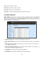
1
MS400870M 24 Port GBE SFP Switch 19” 1U 24X10/100/1000T Combo 100/1000X SFP Network Management User’s Guide Version 0.96 1 Trademarks Contents subject to revise without prior notice. All other trademarks remain the property of their respective owners. Copyright Statement Copyright 2008, All Rights Reserved. This publication may not be reproduced as a whole or in part, in any way whatsoever unless prior consent has been obtained from Company. FCC Warning This equipment has been tested and found to comply with the limits for a Class-A digital device, pursuant to Part 15 of the FCC Rules. These limitations are designed to provide reasonable protection against harmful interference in a residential installation. This equipment generates uses and can radiate radio frequency energy. If this equipment is not installed properly and used in accordance with the instructions, may cause harmful interference to radio communications. However, there is no guarantee that interference will not occur in a particular installation. If this equipment does cause harmful interference to radio or television reception, which can be determined by turning the equipment off and on, the user is encouraged to try to correct the interference by one or more of the following measures: Reorient or relocate the receiving antenna. Increase the separation between the equipment and receiver. Connect the equipment into a different outlet from that the receiver is connected. Consult your local distributors or an experienced radio/TV technician for help. Shielded interface cables must be used in order to comply with emission limits. Changes or modifications to the equipment, which are not approved by the party responsible for compliance, could affect the user‟s authority to operate the equipment. Copyright © 2008 All Rights Reserved. Company has an on-going policy of upgrading its products and it may be possible that information in this document is not up-to-date. Please check with your local distributors for the latest information. No part of this document can be copied or reproduced in any form without written consent from the company. Trademarks: All trade names and trademarks are the properties of their respective companies. 2 Revision History Manual Version 0.95 0.96 Modification Add CLI and Web interface Modify quick keys Firmware Version 1.07.00 1.07.00 Date 2009/06 2009/06 Note: This User’s Manual is written or revised according to the officially-released Firmware version. The content of this Manual is subject to change without prior notice. 3 Table of Contents 1. INTRODUCTION ............................................................................................................... 8 1.1 Interface ....................................................................................................................... 8 1.2 Management Options ................................................................................................... 9 1.3 Management Software ............................................................................................... 10 1.4 Management Preparations ......................................................................................... 11 2. Command Line Interface (CLI) ......................................................................................... 13 2.1 Using the Local Console ............................................................................................ 13 2.2 Remote Console Management - Telnet...................................................................... 14 2.3 Navigating CLI ............................................................................................................ 15 2.3.1 Mode and command summary ............................................................................ 15 2.3.2 General commands and quick keys ..................................................................... 19 2.3.2.1 Quick keys..................................................................................................... 19 2.3.2.2 Listing Command .......................................................................................... 20 2.3.2.3 Show command ........................................................................................... 20 2.3.2.4 Usage Help .................................................................................................. 23 2.3.2.5 Press Any Key to Continue .......................................................................... 23 2.3.2.6 Conventions ................................................................................................. 24 2.4 User mode .................................................................................................................. 24 2.5 Enable mode .............................................................................................................. 26 2.5.1 Backup command mode ..................................................................................... 26 2.5.2 CFM command mode ......................................................................................... 27 2.5.3 Console command mode .................................................................................... 28 2.5.4 IP command mode .............................................................................................. 28 2.5.5 Service command mode ..................................................................................... 29 2.5.6 Syslog command mode ...................................................................................... 32 2.5.7 System command mode ..................................................................................... 32 2.5.8 Time-server command mode .............................................................................. 32 2.5.9 Upgrade command mode ................................................................................... 32 2.5.10 User command mode ........................................................................................ 33 2.6 Config mode ............................................................................................................... 34 2.6.1 Aggr command mode .......................................................................................... 35 2.6.2 CFM command mode ......................................................................................... 36 2.6.3 Dot1x command mode ........................................................................................ 38 2.6.4 IGMP filter command mode ................................................................................ 39 2.6.5 IGMP command mode ........................................................................................ 40 2.6.6 MAC command mode ......................................................................................... 40 2.6.7 Mirror command mode ........................................................................................ 41 2.6.8 MVR command mode ......................................................................................... 41 2.6.9 Port command mode ........................................................................................... 43 2.6.10 QoS command mode ......................................................................................... 43 2.6.11 RSTP command mode ....................................................................................... 46 2.6.12 SKA command mode ......................................................................................... 48 2.6.13 Multicast command mode .................................................................................. 49 2.6.14 Switch command mode ..................................................................................... 50 2.6.15 VLAN command mode ....................................................................................... 50 3. SNMP NETWORK MANAGEMENT................................................................................. 53 4. WEB MANAGEMENT ...................................................................................................... 54 4.1 System Information .................................................................................................... 56 4.2 User Authentication .................................................................................................... 57 4 4.2.1 RADIUS Configuration ......................................................................................... 59 4.3 Network Management ................................................................................................ 60 4.3.1 Network Configuration ......................................................................................... 60 4.3.2 System Service Configuration.............................................................................. 61 4.3.3 RS232/Telnet/Console Configuration ................................................................... 62 4.3.4 Time Server Configuration ................................................................................... 63 4.3.5 Device Community............................................................................................... 64 4.3.6 Trap Destination................................................................................................... 65 4.3.7 Trap Configuration ............................................................................................... 66 4.3.8 Mal-attempt Log Configuration............................................................................. 67 4.4 Switch Management ................................................................................................... 67 4.4.1 Switch Configuration ............................................................................................ 69 4.4.2 Port Configuration ................................................................................................ 70 4.4.3 Link Aggregation .................................................................................................. 71 4.4.3.1 Trunk Mode Configuration ............................................................................. 72 4.4.3.2 Port Trunking ................................................................................................. 73 4.4.3.3 LACP Port Configuration ............................................................................... 74 4.4.4 Rapid Spanning Tree ........................................................................................... 76 4.4.4.1 RSTP Switch Settings ................................................................................... 77 4.4.4.2 RSTP Aggregated Port Settings .................................................................... 78 4.4.4.3 RSTP Physical Port Settings ......................................................................... 80 4.4.5 802.1X Configuration ........................................................................................... 83 4.4.5.1 Configure System .......................................................................................... 83 4.4.5.2 Configure Port Admin State ........................................................................... 84 4.4.5.3 Configure Port Reauthenticate ...................................................................... 85 4.4.6 MAC Address Management ................................................................................. 86 4.4.6.1 MAC Table Learning ...................................................................................... 87 4.4.6.2 Static MAC Table Configuration ..................................................................... 87 4.4.7 VLAN Configuration ............................................................................................. 89 4.4.7.1 Port-Based VLAN .......................................................................................... 89 4.4.7.2 802.1Q VLAN Concept .................................................................................. 91 4.4.7.3 802.1Q VLAN ................................................................................................ 94 4.4.7.3.1 Configure VLAN ...................................................................................... 95 4.4.7.3.2 Configure VLAN Aware........................................................................... 96 4.4.7.3.3 Configure Ingress Filter .......................................................................... 97 4.4.7.3.4 Configure Frame Type ............................................................................ 97 4.4.7.3.5 Configure Port VLAN ID.......................................................................... 98 4.4.7.3.6 Configure Port Egress Mode .................................................................. 99 4.4.8 QoS Configuration ............................................................................................... 99 4.4.8.1 QoS Port Configuration ............................................................................... 100 4.4.8.2 QoS Control List .......................................................................................... 103 4.4.8.3 QoS Rate Limiter ......................................................................................... 105 4.4.8.4 Storm Control .............................................................................................. 106 4.4.9 DSCP Remark ................................................................................................... 107 4.4.10 Port Mirroring ................................................................................................... 109 4.4.11 IGMP Snooping ................................................................................................ 110 4.4.11.1 IGMP Configuration .................................................................................... 111 4.4.11.2 IGMP VLANID Configuration ..................................................................... 112 4.4.11.3 IPMC Segment .......................................................................................... 113 4.4.11.4 IPMC Profile .............................................................................................. 114 5 4.4.11.5 IGMP Filtering............................................................................................ 116 4.4.12 Static Multicast Configuration........................................................................... 117 4.4.13 MVR ................................................................................................................. 119 4.4.13.1 MVR Settings ............................................................................................ 120 4.4.13.2 MVR Group ............................................................................................... 122 4.4.14 SKA Configuration ........................................................................................... 123 4.4.14.1 DHCP Option 82 Settings.......................................................................... 124 4.4.14.2 DHCP Port settings ................................................................................... 126 4.4.14.3 Filter Configuration .................................................................................... 126 4.4.14.4 Static IP Table Configuration ..................................................................... 127 4.4.15 CFM Configuration .......................................................................................... 129 4.4.15.1 Maintenance Domain ................................................................................ 131 4.4.15.2 Maintenance Association Settings ............................................................. 133 4.4.15.3 Maintenance End Point List....................................................................... 135 4.4.15.4 Maintenance End Point Settings ............................................................... 135 4.4.15.5 Loopback Testing ...................................................................................... 137 4.4.15.6 Linktrace Testing ....................................................................................... 138 4.4.15.7 Y.1731 Round-Trip Delay Measurement.................................................... 139 4.4.16 Access Control List Management (ACLM) ...................................................... 139 4.5 Switch Monitor .......................................................................................................... 143 4.5.1 Switch Port State ............................................................................................... 144 4.5.2 Port Traffic Statistics .......................................................................................... 145 4.5.3 Port Packet Error ............................................................................................... 146 4.5.4 Port Packet Analysis Statistics ........................................................................... 147 4.5.5 LACP Monitor .................................................................................................... 148 4.5.5.1 LACP Port Status ........................................................................................ 148 4.5.5.2 LACP Statistics ............................................................................................ 149 4.5.6 RSTP Monitor .................................................................................................... 150 4.5.6.1 RSTP VLAN Bridge Overview ..................................................................... 150 4.5.6.2 RSTP Port Status ........................................................................................ 151 4.5.6.3 RSTP Statistics ........................................................................................... 151 4.5.7 802.1X Monitor .................................................................................................. 152 4.5.7.1 80.2.1X Port Status ..................................................................................... 152 4.5.7.2 802.1X Statistics .......................................................................................... 153 4.5.8 IGMP Snooping Status....................................................................................... 154 4.5.8.1 Snooping Status .......................................................................................... 154 4.5.8.2 IGMP Group Table....................................................................................... 155 4.5.9 MAC Address Table ........................................................................................... 156 4.5.10 SFP Information ............................................................................................... 156 4.5.10.1 SFP Port Information ................................................................................. 156 4.5.10.2 SFP Port State .......................................................................................... 157 4.5.11 DCHP Snooping ............................................................................................... 158 4.5.12 CFM Information .............................................................................................. 159 4.5.12.1 CFM Stack................................................................................................. 160 4.5.12.2 CFM Statistics ........................................................................................... 161 4.5.12.3 Maintenance End Point ............................................................................. 162 4.5.12.4 Remote Maintenance End Points .............................................................. 163 4.5.12.5 Linktrace Reply ......................................................................................... 163 4.6 System Utility ........................................................................................................... 164 4.6.1 Event Log .......................................................................................................... 165 6 4.6.2 Update ............................................................................................................... 166 4.6.3 Load Factory Settings ........................................................................................ 167 4.6.4 Load Factory Settings Except Network Configuration........................................ 168 4.6.5 Backup Configuration ........................................................................................ 168 4.7 Save Configuration ................................................................................................... 169 4.8 Reset System ........................................................................................................... 170 7 1. INTRODUCTION Thank you for using the 24 dual speed combo ports plus 2 Giga combo port Managed Switch. The built-in management module allows users to configure this Managed Switch and monitor the operation status locally or remotely through the network. 1.1 Interface There are 4 models in MS400870M Series. Descriptions and interface figures are provided below: MS400870M-1A – 24 dual speed combo ports plus 2 Giga combo port managed Switch fixed 1 AC MS400870M-2A – 24 dual speed combo ports plus 2 Giga combo port managed Switch fixed 2 Redundant AC MS400870M-1D – 24 dual speed combo ports plus 2 Giga combo port managed Switch fixed 1 DC MS400870M-2D – 24 dual speed combo ports plus 2 Giga combo port managed Switch fixed 2 Redundant DC These 4 models have the same front panel: Figure 1: MS400870M Series Front Panel Each model has different rear panel format: Figure 2-1: MS400870M-1A Rear Panel Figure 2-2: MS400870M-2A Rear Panel Figure 2-3: MS400870M-1D Rear Panel 8 Figure 2-4: MS400870M-2D Rear Panel 1.2 Management Options Switch management options available in MS400870M Series are listed and described below: Local Console Management Telnet Management SNMP Management WEB Management Local Console Management Local Console Management is done through the RS-232 DB-9 Console port located in the back of the MS400870M Series Switch. Direct RS-232 cable connection between the PC and the Managed switch is required for this type of management. Telnet Management Telnet runs over TCP/IP and allows you to establish a management session through the network. Once the Managed switch is on the network with proper configurations, you can use Telnet to login and monitor its status remotely. SNMP Management SNMP is also done over the network. Apart from standard MIB (Management Information Bases), an additional private MIB is also provided for SNMP-based network management system to compile and control. Web Management Web Management is done over the network and can be accessed via a standard web browser, such as Microsoft Internet Explorer. Once the Managed switch is available on the network, you can login and monitor the status of it through a web browser remotely or locally. Local Console-type Web management, especially for the first time use of the Managed Switch to set up the needed IP, can be done through one of the 10/100Base-TX 8pin RJ-45 ports located at the front panel of the Managed Switch. Direct RJ45 LAN cable connection between a PC and the Managed Switch is required for Web Management. 9 1.3 Management Software Following is a list of management software choices for MS400870M Series: Managed switch CLI interface SNMP-based Management Software Web Browser Application Console Program The Managed Switch has a built-in, Command Line Interface called the CLI which you can use to: Configure the system Monitor the status Reset the system You can use CLI as the only management system. However, other network management option - SNMP -based management system is also available. You can access the text-mode Console Program locally by connecting a VT100 terminal - or a workstation running VT100 emulation software - to the Managed Switch RS-232 DB-9 Console port directly. Or, you can use Telnet to login and access the CLI through network connection remotely. SNMP Management System Standard SNMP-based network management system is used to manage the Managed Switch through the network remotely. When you use a SNMP-based network management system, the Managed switch becomes one of the managed devices (network elements) in that system. The Managed switch management module contains an SNMP agent that will respond to the requests from the SNMP-based network management system. These requests, which you can control, can vary from getting system information to setting the device attribute values. The Managed Switch‟s private MIB is provided for you to install in your SNMP-based network management system. Web Browser Application You can manage the Managed Switch through a web browser, such as Internet Explorer or Netscape, etc. (The default IP address of the Managed Switch port can be reached at “http://192.168.0.1”.) For your convenience, you can use either this Web-based Management Browser Application program or other network management option, for example SNMP-based management system as your management system. 10 1.4 Management Preparations After you have decided how to manage your Managed Switch, you are required to connect cables properly, determine the Managed switch IP address and, in some cases, install MIB shipped with your Managed Switch. Connecting the Managed switch It is very important that the proper cables with the correct pin arrangement are used when connecting the Managed switch to another switches, hubs, workstations, etc. 1000Base-X / 100Base-FX SFP Port The small form-factor pluggable (SFP) is a compact optical transceiver used in optical data communications applications. It interfaces a network device mother board (for a switch, router or similar device) to a fiber optic or unshielded twisted pair networking cable. It is a popular industry format supported by several fiber optic component vendors. SFP transceivers are available with a variety of different transmitter and receiver types, allowing users to select the appropriate transceiver for each link to provide the required optical reach over the available optical fiber type. SFP transceivers are also available with a "copper" cable interface, allowing a host device designed primarily for optical fiber communications to also communicate over unshielded twisted pair networking cable. SFP slot for 3.3V mini GBIC module supports hot swappable SFP fiber transceiver. Before connect the other switches, workstation or Media Converter, make sure both side of the SFP transfer are with the same media type, for example: 1000Base-SX to 1000Base-SX, 1000Bas-LX to 1000Base-LX.And check the fiber-optic cable type match the SFP transfer model. To connect to 1000Base-SX transceiver, use the multi-mode fiber cable- with one side must be male duplex LC connector type. To connect to 1000Base-LX transfer, use the single-mode fiber cable-with one side must be male duplex LC connector type. 10/100/1000Base-T RJ-45 Auto-MDI/MDIX Port 24 x 10/100/1000Base-T RJ-45 Auto-MDI/MDIX ports are located at the front of the Managed Switch. These RJ-45 ports allow user to connect their traditional copperbased Ethernet/Fast Ethernet devices to the network. All these ports support autonegotiation and MDI/MDIX auto-crossover, i.e. either crossover or straight through CAT-5 UTP or STP cable may be used. RS-232 DB-9 Port The RS-232 DB-9 port is located at the rear of the Managed Switch. This DB-9 port is used for local, out-of-band management. Since this DB-9 port of the Managed switch is DTE, a null modem is also required to connect the Managed Switch and the PC. 11 By connecting this DB-9 port, it allows you to configure & check the status of Managed Switch even when the network is down. IP Addresses IP addresses have the format n.n.n.n, (The default factory setting is 192.168.0.1). IP addresses are made up of two parts: The first part (for example 192.168.n.n) refers to network address that identifies the network in which the device resides. Network addresses are assigned by three allocation organizations. Depending on your location, each allocation organization assigns a globally unique network number to each network that wishes to connect to the Internet. The second part (for example n.n.0.1) identifies the device within the network. Assigning unique device numbers is your responsibility. If you are unsure of the IP addresses allocated to you, consult with the allocation organization where your IP addresses were obtained. Remember that none of the two devices on a network can have the same address. If you connect to the outside network, you must change all the arbitrary IP addresses to comply with those you have been allocated by the allocation organization. If you do not do this, your outside communications will not be performed. A subnet mask is a filtering system for IP addresses. It allows you to further subdivide your network. You must use the proper subnet mask for proper operation of a network with subnets defined. MIB for Network Management Systems Private MIB (Management Information Bases) is provided for managing the Managed switch through the SNMP-based network management system. You must install the private MIB into your SNMP-based network management system first. The MIB file is shipped together with the Managed Switch. The file name extension is “.mib” that allows SNMP-based compiler can read and compile. 12 2. Command Line Interface (CLI) This chapter introduces you how to use your MS400870M Series CLI, specifically in: Local Console Telnet Configuring the system Resetting the system The interface and options in Local Console and Telnet are the same. The major difference is the type of connection and the port that is used to manage the Managed Switch. 2.1 Using the Local Console Local Console is always done through the RS-232 DB-9 port and requires a direct connection between the switch and a PC. This type of management is useful especially when the network is down and the switch cannot be reached by any other means. You also need the Local Console Management to setup the Switch network configuration for the first time. You can setup the IP address and change the default configuration to desired settings to enable Telnet or SNMP services. Follow these steps to begin a management session using Local Console Management: Step 1. Attach the serial cable the RS-232 DB-9 port located at the back of the Switch with a null modem. Step 2. Attach the other end to the serial port of a PC or workstation. Step 3. Run a terminal emulation program using the following settings: Step 4. Emulation BPS Data bits Parity Stop bits Flow Control Enable VT-100/ANSI compatible 9600 8 None 1 None Terminal keys Press Enter to access the CLI (Command Line Interface) mode. 13 2.2 Remote Console Management - Telnet You can manage the Managed Switch via Telnet session. However, you must first assign a unique IP address to the Switch before doing so. Use the Local Console to login the Managed Switch and assign the IP address for the first time. Follow these steps to manage the Managed Switch through Telnet session: Step 1. Use Local Console to assign an IP address of the Managed Switch, IP address Subnet Mask Default gateway IP address, if required Step 2. Run Telnet. Step 3. Log into the Switch CLI mode. Limitations: When using Telnet, keep the following in mind: Only two active Telnet sessions can access the Managed Switch at the same time. 14 2.3 Navigating CLI The Command Line Interface (CLI) of MS400870M Series is divided into three different modes. After you enter the authorized username and password, you start from the User mode. The commands available depend on which mode you are currently in. Enter a question mark (?) at the system prompt to obtain a list of commands available for each command mode. In CLI management, the User mode only provides users basic functions to operate the Managed Switch. If you would like to configure advanced features of the Managed Switch, such as, VLAN, QoS, Rate limit control, you must enter the Enable or Config mode. The CLI management of this Managed Switch is structured in a hierarchical manner which means that when you want to enter Enable mode you must start from the User mode and enter the required command and password and when you want to enter Config mode you must enter the required command in Enable mode. The following table provides an overview of this Managed Switch. Command Mode User mode Switch Prompt Displayed Access Method Log in From user mode, enter the enable command From the enable mode, enter the config command Enable mode Config mode Exit Method Console> logout Console# exit Console(config)# exit 2.3.1 Mode and command summary Mode User Command cfm enable exit help history Access Method While in User mode, enter cfm command. While in User mode, enter the enable command and a password (press Enter). While in User mode, enter exit command. While in User mode, enter help command. Prompt Console(cfm)> While in User mode, enter Console> 15 Console# Description Run loopback, linktrace and delay measurement test. Enter Enable mode. Username: Exit from current mode. Console> Show available commands that can be used in User mode. List commands that have been used. logout ping show Enable Enter Enable mode backup cfm configure Console disable exit help history history command. While in User mode, enter logout command. While in User mode, enter the ping command and followed by target IP. While in User mode, enter the show command or enter the show command and followed by the command you would like to view its current setting. While in User mode, enter the enable command and a password (press Enter). While in Enable mode, enter the backup command. While in Enable mode, enter the cfm command. While in Enable mode, enter the configure command. While in Enable mode, enter the Console command. While in Enable mode, enter the disable command. While in Enable mode, enter the exit command. While in Enable mode, enter the help command. While in Enable Username: Logout Console> The ping test from the Managed Switch to another network unit. Console> Show a list of commands or show the current setting of each listed command. Console# Enter Enable mode. Console(backup)# Backup configuration file via FTP or TFTP. Console(cfm)# Run loopback linktrace and delay measurement test. Enter Config mode. Console(config)# Console(Console)# Set up time-out timer when the user is inactive. Console> Exit from current mode. Console> Exit from current mode. Console# Show available commands that can be used in Enable mode. List commands that Console# 16 ip logout ping reboot restore service syslog system time-server upgrade user write show mode, enter the history command. While in Enable mode, enter the ip command. While in Enable mode, enter the logout command. While in Enable mode, enter the ping command and followed by target IP. While in Enable mode, enter the reboot command. While in Enable mode, enter the restore command. While in Enable mode, enter the service command. While in Enable mode, enter the syslog command. While in Enable mode, enter the system command. While in Enable mode, enter the time-server command. While in Enable mode, enter the upgrade command. While in Enable mode, enter the user command. While in Enable mode, enter the write command. have been used. Console(ip)# Username: Console# The ping test from the Managed Switch to another network unit. Boot-up message To restart the Managed Switch. Console# Load factory settings Console(service)# Configure the network management service. Configure the Switch syslog parameters. Console(syslog)# Console(system)# Console(timeserver)# Console(upgrade)# Console(user)# Console# While in Enable Console# mode, enter the show command or enter the show command and followed by the 17 Configure IP addresses of the Managed Switch. Logout Configure the Managed Switch‟s basic information. Synchronize the time of a computer client or server to another server. Upgrade the Managed Switch‟s firmware and restore the previous settings. Configure user accounts. Save configuration to the Managed Switch‟s flash memory. Show a list of commands or show the current setting of each listed command. Config Enter Config mode aggr cfm dot1x exit help history igmpfilter igmp mac mirror mvr port command you would like to view its current setting. While in Enable mode, enter the configure command. Console(config)# When in Config mode, enter the aggr command. When in Config mode, enter the cfm command. Console(configaggr)# When in Config mode, enter the dot1x command. Console(configdot1x)# When in Config mode, enter the exit command. When in Config mode, enter the help command. Console# When in Config mode, enter the history command. When in Config mode, enter the igmpfilter command. When in Config mode, enter the igmp command. When in Config mode, enter the mac command. When in Config mode, enter the mirror command. When in Config mode, enter the mvr command. When in Config Console(config)# Console(config-cfm)# Console(config)# 18 In Enable mode, users can access the Switch‟s advanced features, such as VLAN, Rate limit, QoS, etc. Configure LACP functions. Configure the Managed Switch OAM 802.1ag CFM settings. Configure the Managed Switch to send information when 802.1x client authenticates via the Switch. Exit from current mode Show available commands that can be used in Config mode. List commands that have been used. Console(configigmpfilter)# Configure IGMP filtering settings. Console(configigmp)# Configure IGMP settings. Console(configmac)# Set up each port‟s MAC learning function. Set up target port for mirroring. Console(configmirror)# Console(config-mvr)# Configure Multicast VLAN Registration (MVR) settings. Console(config)# Configure the status qos rstp ska multicast switch vlan show mode, enter the port command. When in Config mode, enter the qos command. When in Config mode, enter the rstp command. When in Config mode, enter the ska command. of each port. Console(config-qos)# When in Config mode, enter the multicast command. When in Config mode, enter the switch command. Set up the priority of packets within the Managed Switch. Console(config-rstp)# Set up each port and aggregated ports‟ RSTP status. Console(config-ska)# Configure Secure Customer Connections (SKA) settings. Console(configConfigure static multicast)# multicast settings. Console(configswitch)# When in Config Console(configmode, enter the vlan)# vlan command. When in Config Console(config)# mode, enter the show command or enter the show command and followed by the command you would like to view its current setting. Set up acceptable frame size and address learning, etc. Set up VLAN mode and VLAN configuration. Show a list of commands or show the current setting of each listed command. 2.3.2 General commands and quick keys 2.3.2.1 Quick keys Using the key or entering the command… Enter the “?” commands Enter the “help” commands Enter incomplete characters then enter the question mark (?) Enter the “exit” command Enter the “history” command To do this… Obtain a list of available commands in the current mode. Obtain a list of available commands in the current mode. List all commands similar to incomplete characters. Return to the former mode or login screen. List all commands that have been used. 19 Press the direction or key Enter unique part of a command and press TAB key Scroll through the command history. The switch will automatically display the full command. 2.3.2.2 Listing Command After entering the question mark (?) at the prompt line, the screen will show a list of commands available for each command mode. 2- 3- 4- 11. Command Prompt: The command prompt shows the mode that is currently configured. Users can type in commands or characters after the prompt. Entering commands or characters Currently configured mode 2. Command: This column lists all commands that are available in the current mode. 3. Purpose & Description: This column lists each command‟s purpose and description in the current mode. 4. Usage: This column lists each command‟s usage in the current mode. 2.3.2.3 Show command In each mode, users can enter show command to view a list of commands, view each command‟s current setting, and view system information. The following explains how “show” command is used in MS400870M Series. Show system When you enter “show system” command in each mode, you will be informed of system information. The following screen page shows a sample of system information in User mode. 20 Company Name: This shows the company name or related information. System Object ID: This shows the predefined System OID. System Contact: This shows the system contact information. System Name: This shows the system name or related descriptions. System Location: This shows the system location. Model Name: This shows the product model name. Firmware Version: This shows the firmware version of this Managed Switch. M/B Version: This shows the motherboard version of this Managed Switch. Serial Number: This shows the serial number of this Managed Switch. Date Code: This shows the date code of this Managed Switch. Up Time: This shows how long this Managed Switch has been turned on since the last reboot. Local Time: This shows the local time of the device. Show available commands In User, Enable and Config mode, you can type “show” to view a list of commands available. 21 Show a Command’s Current Settings In User, Enable and Config mode, you can type “show” and followed by the command listed above to view its current setting. For example, if you type “show qos” in User mode (Console>), then the current setting of qos command will be displayed. Within QoS, the rate limit configurations can be set. You can type “show qos rate-limit” in any mode to view its current setting. Show Currently-Configured Settings When you type a specific command in Enable or Config mode to configure or edit the setting of a certain function, you can type “show” to verify the setting you have just configured or 22 edited. For example, when you are in Console(console)# and have changed the setting of time-out function, you can type “show” after “Console(console)#” prompt, then you can verify the currently-configured setting of time-out function. 2.3.2.4 Usage Help When entering a command without the required parameter, the system will remind users of the command‟s syntax and parameter. 2.3.2.5 Press Any Key to Continue When a command generates more than one page outputs, the prompt “Press Ctrl-C to exit or any key to continue!” will be displayed at the bottom of the screen. Simply press any key to view next page information or press Ctrl-C to return to the prompt line. 23 2.3.2.6 Conventions In CLI, some conventions are used consistently to express uses of a parameter. Common conventions are described below. Conventions < > [ ] <port_list> <enable | disable> <administrator | read_and_write | read_only | access_denied> [etype <etype (0x600-FFFF)> | vid <vid(1-4094)> | port <udp_tcp_port(065535)> |dscp <dscp(0-63)> | tos <tos_list(0-7)> | tag_prio <tag_prio_list(0-7)>] Descriptions Required parameters or values are in angle brackets. Optional parameters or values are in square brackets. For example: [qce_id] or [etype <etype (0x600-FFFF)> | vid <vid(1-4094)> | port <udp_tcp_port(0-65535)> |dscp <dscp(0-63)> | tos <tos_list(0-7)> | tag_prio <tag_prio_list(0-7)>] “port_list” allows you to enter several discontinuous port number, separating by a comma, for example, port “5, 7, 9, 12”; or, you can enter continuous port numbers with a dash and separating by a comma, for example, port “1-5, 7-9, 12-15.” Two options, separated by a vertical bar, are available for selection. Select one option within the angle bracket. Several options, separated by a vertical bar, are available for selection. Select one option within the angle bracket. This is an optional parameter or value and six parameters are available for selection. 2.4 User mode When you use CLI, you will start in the User mode. The User mode provides basic configurations and ping test of the Managed Switch. In User mode, users can assign Switch IP address, mask and gateway. Access to User mode When the Managed Switch is turned on, boot-up message will be displayed first and then followed by username and password prompt (Default username is admin. No password is required for default setting thus press Enter key in password prompt.). When system prompt shows “Console>”, it means the user has successfully entered the User mode. 24 Boot up message Root directory (Default username: admin without password) In “Console>”, enter the question mark (?) to show all commands available for User mode. The screen shows as follows: Command cfm enable exit help history logout ping show Description Run OAM 802.1ag CFM loopback, linktrace, delay measurement test. Enter the Enable mode. Leave the User mode. Display a list of available commands in User mode. Display the command history. Logout from the Managed Switch. Allow users to ping a specified network device. Show a list of commands or show the current setting of each listed command. 25 2.5 Enable mode In order to manage the Managed Switch and set up required switching functions, enter the enable command after the “Console>” and then press ? for a list of commands available for use. Command backup cfm configure console disable exit help history ip logout ping reboot restore service syslog system time-server upgrade user Show Description Backup configuration file via FTP or TFTP. Run OAM 802.1ag CFM loopback, linktrace, delay measurement test. Enter Config mode. Set up time-out time. Exit Enable mode and return to User Mode. Exit Enable mode and return to User Mode. Display a list of available commands in Enable mode. Show commands that have been used. Assign IP addresses manually or automatically. Logout from the Managed Switch. Allow users to ping a specified network device. Restart the Managed Switch. Restore configuration via FTP or TFTP. Three different management services are provided to configure the Managed Switch; these are “Telnet”, “SNMP”, and “Web”. Configure the Managed Switch‟s syslog settings. Configure system information. Synchronize the time of a computer client or server to another server. Allow users to update firmware and restore configuration via FTP or TFTP. Set up a user account and its access privilege. Show a list of commands or show the current setting of each listed command. 2.5.1 Backup command mode Prompt Console(backup)# Command & Parameter auto-backup <ftp | tftp><server ip> <username> <password> <file directory> <0-23 o'clock> auto-backup <enable | disable> config <ftp | tftp> <server ip> <username> <password> <file directory> 26 Description To configure auto-backup settings. The system will backup configuration file. To enable or disable auto-backup function. To backup configuration file immediately. 2.5.2 CFM command mode Ethernet Connectivity Fault Management (CFM) is an end-to-end and service-to-service Ethernet layer operations, administration and maintenance (OAM) 802.1ag protocol. It includes practical connectivity monitoring, fault verification and fault isolation for large Ethernet metropolitan-area networks (MANs) and WANs. As its name implies, IEEE 802.1ag focuses on the connectivity fault management which provides the following four features on each Virtual Local Area Network (VLAN) basis. Fault Detection/Fault notification Fault verification Fault isolation Fault Detection/Fault notification IEEE 802.1ag supports fault detection through Continuity Check Messages (CCM). CCM is somewhat like the “keep-alive” message. By default, every 802.1ag-capable network device (ND) sends out “heart-beat” style CCM periodically. Hence, by configuring a list of expected existent remote 802.1ag-capable NDs, the local 802.1ag-capable ND can detect the health status of its connection to the remote ND. Fault verification IEEE 802.1ag supports fault verification through Loopback Messages (LBM) and Loopback Reply (LBR). The LBM/LBR mechanism is similar to ICMP “ping” function in the IP network. However, since the interfaces of an ND in an Ethernet network may not possess their individual IP address, the operator can not achieve fault verification by ICMP “ping” in such a network environment. Fault isolation In addition to the LBM/LBR mechanism, IEEE 802.1ag supports fault isolation through Linktrace Messages (LTM) and Linktrace Reply (LTR). The LTM/LTR mechanism is similar to the “trace route” function in the IP network. However, since the interfaces of an ND in an Ethernet network may not possess their individual IP address, the operator can not achieve fault isolation by “trace route” in such a network environment. IEEE 802.1ag also defines the following network error status to be conveyed in the CCM. MACstatus Either some remote ND is reporting its interface as not ready to pass both the data packets and BPDU, or all remote NDs are reporting their interfaces as not able to pass ordinary data packets. RemoteCCM The ND is not receiving valid CCMs from at least one of the remote NDs. ErrorCCM The ND has received at least one invalid CCM whose CCM Interval has not yet timed out. XconCCM The ND has received at least one CCM from either another VLAN or a lower MD Level whose CCM Interval has not yet timed out. 27 Prompt Command & Parameter Console(cfm)# Description loopback <domain_name> <assoc_name> <target mepid | mac address>[-n number(2100)] [-s size(1-255)] [-p priority(0-7)] [-d drop eligible(true|false)] linktrace <domain_name> <assoc_name> <target mepid | mac address>[-f flag(fdbonly | none)] [-h hop count(1-255)] de-measure <domain_name> <assoc_name> <target mepid | mac address>[-n number(2100)] [-p priority(0-7)] Run loopback test. For Example: Console(cfm)#loopback domain assoc 00:01:02:03:04:05 -n 100 -s 255 -p 3 -d true Run linktrace test. For Example: Console(cfm)# linktrace domain assoc 00:01:02:03:04:05 -f none -h 100 Run delay measurement test. For Example: Console(cfm)#de-measure domain assoc 00:01:02:03:04:05 -n 100 -p 0 2.5.3 Console command mode Prompt Command & Parameter Console(Console)# Description To disconnect the Managed Switch when the user is inactive. time-out <secs> <secs>: 0 or 5-9999 seconds For example: Console(Console)#time-out 300 2.5.4 IP command mode Prompt Console(ip)# Command & Parameter type <manual | dhcp> address <ip> <mask> <gw> Description If “DHCP” is selected and a DHCP server is also available on the network, the Managed Switch will automatically get the IP address from the DHCP server. If "Manual" mode is selected, the user needs to specify the IP address, Subnet Mask and Gateway. For example: Console(ip)# type manual Enter the unique IP address of this Managed Switch. You can use the default IP address or specify a new one when address duplication occurs or the address does not match up with your network. (Default IP address is 192.168.0.1) For example: Console(ip)# address 192.110.1.2 Specify the subnet mask to the Switch IP address. The default subnet mask values for the three Internet address classes are as follows: Class A: 255.0.0.0 Class B: 255.255.0.0 Class C: 255.255.255.0 For example: 28 Console(ip)# address 192.110.1.2 255.255.255.0 Specify the IP address of a gateway or a router, which is responsible for the delivery of the IP packets sent by the Switch. This address is required when the Switch and the network management station are on different networks or subnets. The default value of this parameter is 0.0.0.0, which means no gateway exists and the network management station and Switch are on the same network. For example: Console(ip)# address 192.110.1.2 255.255.255.0 120.110.1.5 2.5.5 Service command mode Prompt Console(servicetelnet)# Command & Parameter mode <enable | disable> Console(snmpcommunity)# mode <enable | disable> For example: Console(service-telnet)#port 23 In service command mode, it provides three modes for users to choose from, these are “telnet”, “snmp” and “web”. If you type “snmp”, you can set up either to enable or disable this mode. For example: Console(service-snmp)#mode enable Add a new community. The name of the community is up to 20 alphanumeric characters. add<community> For example: Console(snmp-community)#add myswitch To delete a community that is already added to the Managed switch. delete<community> Console(snmpcommunity_commnity name)# In service command mode, it provides three modes for users to choose from, these are “telnet”, “snmp” and “web”. If you type “telnet”, you can set up whether to enable or disable this mode. For example: Console(service-telnet)#mode enable When telnet is enabled, you can set up the port number that allows telnet access. The default port number is set to 23 in telnet mode. However, you can also identify a port number between 1025 and 65535. port <telnet_port> Console(servicesnmp)# Description state <enable | disable> description <description> ip <enable | disable> 29 For example: Console(snmp-community)#delete myswitch To enable or disable community function. Enter a unique description for this community name, up to 35 alphanumeric characters. This is mainly for reference only. To enable or disable IP security. If enabled, Community may access the Managed Switch ip_addr <ip_addr> level <administrator | read_and_write | read_only | access_denied> only through the management station, which has the exact IP address specified in IP address field below. If disabled, Community can access the Managed Switch through any management stations. Specify the IP address used for IP Security function. Specify the desired privilege for the SNMP operation. <administrator | read_and_write | read_only | access_denied>: Four operation privileges are available in the Managed Switch. Administrator: Full access right includes maintaining user account & system information, loading factory settings, etc. Read & Write: Full access right but cannot modify user account & system information and load factory settings. Read Only: Allow to view only. Access Denied: Completely forbidden for access. NOTE 1: When the community browses the Managed Switch without proper access right, the Managed Switch will respond nothing. For example, if a community only has Read & Write privilege, then it cannot browse the Managed Switch’s user table. NOTE 2: If you would like to edit the settings of your new account, you can enter the command community community name under the Console(service-snmp)#. For example: If you want to edit settings of the account “salesdept”, you can use the following commands to enter the editing mode. Console(snmp-trapdest)# Console#service Console(service)#snmp Console(service-snmp)#community salesdept Console(snmp-community_salesdept)# To add a new trap destination. This function will send trap to the specified destination. add <trap_id> <trap_ip> <community> <trap_id>: 1~10 <trap_ip>: The specific IP address of the network management system that will receive the trap. <community>: up to 20 characters. NOTE: If you would like to edit the settings of a trap destination, you can enter the command trap-dest trap id under the Console(service- 30 snmp)#. For example: If you want to edit settings of the trap destination “2”, you can use the following commands to enter the editing mode. Console(snmp-trapdest_trap id)# Console(snmp-trapmode)# delete <trap_id> state <enable | disable> Console#service Console (service)#snmp Console (service-snmp)#trap-dest 2 Console (snmp-trap-dest_2)# To delete a registered trap destination. To enable or disable this trap destination. destination <ip_addr> For example: Console(snmp-trap-dest_trap id)#state enable Specify the IP address of this trap destination. community<community> <ip_addr>: Enter the trap destination IP address. Enter the community name. cold-start <enable | disable> warm-start <enable | disable> auth-fail <enable | disable> port-link <enable | disable> storm <enable | disable> upper-limit <packets/secs> power-down <enable | disable> case-fan <enable | disable> sfp <enable | disable> Console(service-web)# all <enable | disable> Example : all enable mode <enable | disable> 31 <community>: Enter the community name of up to 20 characters. To enable or disable the Managed Switch to send a trap when the Managed Switch cold starts. To enable or disable the Managed Switch to send a trap when the Managed Switch warm starts. To enable or disable the Managed Switch to send authentication failure trap when any unauthorized users attempt to login. To enable or disable the Managed Switch to send port Link Up/Down trap. To enable or disable broadcast storm trap sending from the Managed Switch when broadcast packets reach the upper limit. The broadcast storm trap will be sent when the Managed Switch exceeds the specified limit. <packets/secs>: 0~148810 Send a trap notice while the Managed Switch is power down. To enable or disable the Managed Switch to send a trap when fan is not working or failed. To enable or disable the Managed Switch to send SFP abnormality trap. To set up all situations above as enabled or disabled. To enable or disable web management. 2.5.6 Syslog command mode Prompt Command & Parameter Console(syslog)# Description To enable or disable syslog. Set up the first syslog server IP. Set up the second syslog server IP. Set up the third syslog server IP. mode <enable | disable> server-1 <ip_addr1> server-2 <ip_addr2> server-3 <ip_addr3> 2.5.7 System command mode Prompt Console(system)# Command & Parameter company <company_name> syscontact <system_contact> sysname <system_name> syslocation <system_location> Description Specify a company name of up to 55 alphanumeric characters. Enter contact information for this Managed switch, up to 55 alphanumeric characters. Enter a unique name for this Managed Switch, up to 55 alphanumeric characters. Use a descriptive name to identify the Managed Switch in relation to your network, for example, “Backbone 1”. This name is mainly used for reference only. Enter a brief description of the Managed Switch location, up to 55 alphanumeric characters. As the name implies, the location is for reference only, for example, “13th Floor”. 2.5.8 Time-server command mode Prompt Console(time-server)# Command & Parameter mode <enable | disable> ip-addr <ip_addr> [test] 2nd-addr <2nd_addr> [test] syninterval <minutes> Description To enable or disable time-server. Enter the NTP time server IP address. Enter the second NTP time server IP address. The interval time to synchronize from NTP time server. <minutes>: 1~99999 minutes time-zone<number> day-saving <enable | disable> offset <hour> For example: Console(time-server)#syninterval 50 Select the appropriate time zone from the list provided. To enable or disable the daylight saving time function. To offset 1 hour or 2 hours for daylight saving function. 2.5.9 Upgrade command mode Prompt Console(upgrade)# Command & Parameter firmware <ftp|tftp> <serverip> <username> <password> <filelocation> 32 Description To upgrade Firmware via FTP or TFTP. <serverip>: Enter the IP address of the config <ftp|tftp> <serverip> <username> <password> <filelocation> FTP or TFTP server. <username>: Enter the username for Firmware upgrade via FTP. If you use TFTP server to upgrade Firmware, you do not need to specify username. <password>: Enter the password for Firmware upgrade via FTP. If you use TFTP server to upgrade Firmware, you do not need to specify password. <filelocation>: Enter the file location within the FTP or TFTP server. To restore configuration via FTP or TFTP server. <serverip>: Enter the IP address of the FTP or TFTP server. <username>: Enter the username for Firmware upgrade via FTP. If you use TFTP server to upgrade Firmware, you do not need to specify username. <password>: Enter the password for Firmware upgrade via FTP. If you use TFTP server to upgrade Firmware, you do not need to specify password. <filelocation>: Enter the file location within the FTP or TFTP server. 2.5.10 User command mode Command Console(user)# Parameter Description add <username> [password] <administrator | read_and_write | read_only | access_denied> Add a new user and specify its access privilege. <administrator | read_and_write | read_only | access_denied>: Four operation privileges are available in the Managed Switch. Administrator: Full access right includes maintaining user account & system information, loading factory settings, etc. Read & Write: Full access right but cannot modify user account & system information and load factory settings. Read Only: Allow to view only. Access Denied: Completely forbidden for access. For example: Console(user)#add user1 user1 administrator Delete a registered user. delete <username> Console(userradius)# For example: Console(user)#delete user1 To enable or disable RADIUS Authentication. mode <enable | disable> 33 The word or characters to encrypt data sent to RADIUS server. The word or characters are up to 31 characters. The RADIUS service port on RADIUS server. secret <secret> port <port> <port>: The port number is between 1025 and 65535. For example: Console(user-radius)#port 1812 The number of trying to reconnect if the RADISU server is not reachable. retry-time <retry_time> <retry_time>: 0~2 For example: Console(user-radius)#retry-time 2 IP address of the first RADIUS server. IP address of the second RADIUS server. ip-addr <ip_addr> 2nd-addr <ip_addr> 2.6 Config mode In order to manage the Managed Switch and set up advanced switching functions, enter the configure command from Console# directory and then type in “?”. Then, the screen shows as follows: Command aggr cfm dot1x exit help history igmpfilter igmp mac mirror Description Configure LACP functions. Configure the Managed Switch OAM 802.1ag CFM settings. Configure the Managed Switch to send information when 802.1x client authenticates via the Switch. Exit the config mode. Display a list of available commands in Config mode. Show commands that have been used. Configure IGMP filtering settings. Configure IGMP settings. Set up each port‟s MAC learning function. Set up target port for mirroring. 34 mvr port qos rstp ska multicast switch vlan show Configure Multicast VLAN Registration (MVR) settings. Configure the status of each port. Set up the priority of packets within the Managed Switch. Set up each port and aggregated ports‟ RSTP status. Configure Secure Customer Connections (SKA) settings. Configure static multicast settings. Set up acceptable frame size and address learning, etc. Set up VLAN mode and VLAN configuration. Show a list of commands or show the current setting of each listed command. 2.6.1 Aggr command mode Link aggregation is an inexpensive way to set up a high-speed backbone network that transfers much more data than any one single port or device can deliver without replacing everything and buying new hardware. For most backbone installations, it is common to install more cabling or fiber optic pairs than initially necessary, even if there is no immediate need for the additional cabling. This action is taken because labor costs are higher than the cost of the cable and running extra cable reduces future labor costs if networking needs changes. Link aggregation can allow the use of these extra cables to increase backbone speeds with little or no extra cost if ports are available. This Managed switch supports 2 link aggregation modes: static Port Trunk and dynamic Link Aggregation Control Protocol (LACP) using the IEEE 802.3ad standard. These allow several devices to communicate simultaneously at their full single-port speed while not allowing any one single device to occupy all available backbone capacities. Prompt Console(configaggr)# Command & Parameter Description The Managed Switch allows users to create 13 trunking groups. Each group consists of 2 to 16 links (ports). add <port_list> <aggr_id> <port_list>: 1~26 <aggr_id>:1~13 For example: Console(config-aggr)#add 1-4,10-15,19 10 Delete an aggregation ID. delete <aggr_id> <aggr_id>:1~13 Console(configaggr-lacp)# mode <smac | dmac> <enable | disable> For example: Console(config-aggr)#delete 10 Enable or disable packets according to source and destination MAC address state <port_list> <enable | disable> For example: Console(config-aggr)#mode dmac enable This Managed Switch allows users to indicate which port(s) are enabled to use LACP. For example: Console(config-aggr-lacp)# state 1-4,10-15,18,19 enable 35 Specify the key value to the selected ports. key <port_list> <key> <port_list>: 1~26 <key>: The range of key value is from 0 to 255. For example: Console(config-aggr-lacp)# key 1-4,10-15,18,19 200 To set up whether LACP ports are active or passive. role <port_list> <active | passive> <port_list>: 1~26 <active | passive>: Active LACP ports are capable of processing and sending LACP control frames. This allows LACP compliant devices to negotiate the aggregated link so that the group may be changed dynamically as required. In order to utilize the ability to change an aggregated port group, that is, to add or remove ports from the group, at least one of the participating devices must designate LACP ports as active. Both devices must support LACP. LACP ports that are designated as passive cannot initially send LACP control frames. In order to allow the linked port group to negotiate adjustments and make changes dynamically, one end of the connection must have “active” LACP ports. For example: Console(config-aggr-lacp)# role 1-4,10-15,18,19 active 2.6.2 CFM command mode Prompt Console(configcfm-dom)# Command & Parameter add <domain_name> <level> <mhf> Description This allows the user to register a CFM maintenance domain. <domain_name>: up to 22 characters. <level>: 0~7 <mhf>: Specify MHF as “default” “explicit” or “none”. Default: MHFs can be created for this VID on any Bridge Port through which the VID can pass. Explicit: MHFs can be created on CFM VLAN member port and only if there is a MEP at the lower active MD-level on the port. None: No MHFs can be created for this VID. For example: Console(config-cfm-dom)#add mydomain 7 none To delete a registered domain name. delete <domain_name> 36 Console(configcfm-dom_domain name)# For example: Console(config-cfm-dom)#delete mydomain To specify maintenance domain level for the registered domain name. level <level> <level>: 0~7 mhf <default | explicit | none> For example: Console(config-cfm-dom_mymy)#level 7 To specify MHF for the registered domain name. <default | explicit | none>: Three options are available for this function. Default: MHFs can be created for this VID on any Bridge Port through which the VID can pass. Explicit: MHFs can be created on CFM VLAN member port and only if there is a MEP at the lower active MD-level on the port. None: No MHFs can be created for this VID. For example: Console(config-cfm-dom_mymy)#mhf none NOTE: If you would like to edit the settings of your new domain, you can enter the command domain domain name under the Console(config-cfm)#. For example: If you want to edit settings of the account “mydomain”, you can use the following commands to enter the editing mode. Console(configcfm-assoc)# add <assoc_name> <vlan_id> <ccm_interval> <mhf> Console(config-cfm)#domain mydomain Console(snmp-community_mydomain)# This allows users to register a maintenance association. <assoc_name>: up to 20 characters. <vlan_id>: 0 (None);1~4094 <ccm_interval>: 0:no 1:1s 2:10s 3:1m 4:10m <mhf>: Four options are available for this function. Defer: The control of MHF creation is deferred to the corresponding variable in the enclosing Maintenance Domain. Default: MHFs can be created for this VID on any Bridge Port through which the VID can pass. Explicit: MHFs can be created on CFM VLAN member port, and only if there is a MEP at the 37 lower active MD-level on the port. None: No MHFs can be created for this VID. For example: Console(config-cfm-assoc)#add myassoc 1 4 none To delete a registered association name. delete <assoc_name> Console(configcfm)# loopback <target mepid | mac_address>[-n number(2-100)] [-s size(1-255)] [-p priority(0-7)] [-d drop_eligible(true | false)] linktrace <target mepid | mac_address> [-f flag(fdbonly | none)][-h hop_count(1-255)] de-measure <target mepid | mac_address> [-n number(2-100)] [-p priority(0-7)] For example: Console(config-cfm-assoc)#delete myassoc To configure loopback test settings. For Example: Console(cfm)#loopback domain assoc 00:01:02:03:04:05 -n 100 -s 255 -p 3 -d true To configure linktrace settings. For Example: Console(cfm)# linktrace domain assoc 00:01:02:03:04:05 -f none -h 100 To configure delay measurement settings. For Example: Console(cfm)#de-measure domain assoc 00:01:02:03:04:05 -n 100 -p 0 2.6.3 Dot1x command mode Prompt Console(configdot1x-sys)# Command & Parameter server <ip_addr> secret <shared_secret> To enable or disable 802.1X for the Managed Switch. RADIUS Authentication server address. The identification word or number assigned to each RADIUS authentication server with which the client shares a secret. reauth <enable | disable> period <reauth_period> <shared_secret>: up to 30 characters To enable or disable Reauthentication. The time interval that the system sends out periodic reauthentication message. mode <enable | disable> eap-timeout <eapol_timeout> Console(configdot1x)# Description state <port_list> <auto | authorized | unauthorized> <reauth_period>: 0~3600 Seconds The time that the Managed Switch waits for responses from the server host to an authentication request. <eapol_timeout>: 1~255 Seconds Specify each port‟s authentication statue. <auto | authorized | unauthorized>: Authorized: This forces the port to grant access to all clients, either dot1x-aware or otherwise. “Authorized” is the default setting. Unauthorized: This forces the port to deny access to all clients, either dot1x-aware or otherwise. 38 Auto: This requires a dot1x-aware client to be authorized by the authentication server. Accesses from clients that are not dot1x‑aware will be denied. For example: Console(config-dot1x)#state 1-4,10-15,18,19 auto This will automatically send out authentication message to selected clients. authentic <port_list> <port_list>: 1~26 For example: Console(config-dot1x)#authentic 1-4,1015,18,19 2.6.4 IGMP filter command mode Prompt Console(configsegment)# Command & Parameter add <seg_id> <seg_name> <ip> <ip> Description To create a segment. <seg_id>: 1~400 <seg_name>: up to 20 characters <ip>: The IP range is from 224.0.1.0~238.255. 255.255 Console(configprofile)# delete <seg_id> add <profile_name> <seg_id> <seg_id> …. For example: Console(config-segment)# add 2 myseg 224.0.1.5 235.255.255.253 To delete a registered segment. To create a profile. <profile_name>: up to 20 characters <seg_id>: 1~400 (The field for segment ID is from the entry registered in Segment option.) Console(configigmpfilter)# For Example: Console(config-profile)#add myprofile 2 To delete a registered profile. To enable or disable IGMP filtering Specify the maximum transport multicast stream. delete <profile_name> mode <enable | disable> channel <port_list> <1-10> <port_list>: 1~26 <1-10>: Channel limit from 1 to 10 state <port_list> <enable | disable> For example: Console(config-igmpfilter)# channel 1-4,1015,18,19 10 To enable or disable each port‟s IGMP filtering function. <port_list>: 1~26 For example: Console(config-igmpfilter)# state 1-4 enable 39 filter <port_list> <profile_name> <profile_name>… This allows information of specified IPMC Profile to pass-through. <port_list>: 1~26 <profile_name> This field for IPMC Profile name is from the entry registered in IPMC Profile option. For example: Console(config-igmpfilter)# filter 1-4 mypro 2.6.5 IGMP command mode Prompt Console(configigmp)# Command & Parameter Description To enable or disable IGMP function. To set up which ports belong to router ports mode <enable | disable> router-port <port_list> <port_list>: 1~26 For example: Console(config-igmp)# router-port 1-4,1015,18,19 Set forwarding mode for unregistered (not-joined) IP multicast traffic. The traffic will flood when enabled. However, the traffic will forward to routerports only when disabled. When enabled, the port in VLAN will monitor network traffic and determine which hosts want to receive the multicast traffic. flooding <enable | disable> vlanstate <vid> <enable | disable> <vid>: 1~4094 For example: Console(config-igmp)#vlanstate 1 enable When enabled, the port in VLAN can serve as the Querier which is responsible for asking hosts whether they want to receive multicast traffic. vlanquerier <vid> <enable | disable> <vid>: 1~4094 For example: Console(config-igmp)#vlanquerier 1 enable The Query Interval is used to set the time between transmitting IGMP queries. interval <num> <num>:1~6000 Seconds This determines the maximum amount of time allowed before sending an IGMP response report. maxresponse <num> fast-leave <enable | disable> <num>: 1~6000(1/10Secs) The Fast Leave option may be enabled or disabled. This allows an interface to be ignored without sending group-specific queries. 2.6.6 MAC command mode Prompt Command & Parameter 40 Description Console(configmac)# To set up each port‟s MAC learning function. learning <port_list> <auto | disable> <port_list>: 1~26 Console(configmac-static)# add <mac-addr> <vlan_id> <port | filter> delete <mac-addr> <vlan_id> <port | filter> For example: Console(config-mac)# learning 1-4,10-15,18,19 auto Specify a destination MAC address in the packet and the VLAN where the packets with the Destination MAC address can be forwarded. <vlan_id>: 1~4094 <port | filter>: port:1~26 filter:27 Delete a MAC address setting. 2.6.7 Mirror command mode Prompt Console(configmirror)# Command & Parameter Description To enable or disable Target Port‟s mirroring on the TX and RX of Source port. port <mirror_port_list> <mirror_port_list>: 1~26 For example: Console(config-mirror)# port 1-4,10-15,18,19 Specify the preferred target port for mirroring. Target-port <target_port | disable> <target_port>: 1~26 or 0 (disabled) For example: Console(config-mirror)#target-port 24 2.6.8 MVR command mode MVR refers to Multicast VLAN Registration that enables a media server to transmit multicast stream in a single multicast VLAN when clients receiving multicast VLAN stream can reside in different VLANs. Clients in different VLANs intend to join or leave the multicast group simply by sending the IGMP Join or Leave message to a receiver port. The receiver port that belongs to one of the multicast groups can receive multicast stream from the media server. MVR Configuration Guidelines and Limitations Guidelines: Enable IGMP global setting. Enable MVR global setting. Create MVR VLAN and indicate the Source port and Receive port. Create MVR Groups whose multicasting channels would belong to MVR VLAN. Enable VLAN Aware in MVR Source Port. In a normal condition, Tag multicasting stream injects to Source port. (Optional) 41 Setting VLAN Port Egress mode in MVR Receive port. In a normal condition, Un-tag multicasting stream forward to receive port. (Optional) Limitation Receiver ports on a switch can be in different VLANs, but they should not belong to the multicast VLAN. Do not configure MVR on private VLAN ports. MVR can coexist with IGMP snooping on a switch. MVR data received on an MVR receiver port is not forwarded to MVR source ports. MVR does not support IGMPv3 messages. MVR on IPv6 multicast groups is not supported. Prompt Console(configmvr)# Command & Parameter mode <enable | disable> add <vlan_id> <rec_port_list> <sor_port_list> Description To enable or disable MVR global setting To add a MVR VLAN ID and specify its Receive and Source Port. <vlan_id>: 1~4094 <rec_port_list>: 1~26 <sor_port_list>: 1~26 For example: Console(config-mvr)#add 4094 1-4,10-15,18,19 59,16,17 To delete a registered MVR VLAN ID. delete <vlan_id> <vlan_id>: 1~4094 Console(configmvr-group)# For example: Console(config-mvr)#delete 4094 To add a new MVR group and specify the multicasting channel that would belong to MVR VLAN. add <vlan_id> <ip> <ip> <vlan_id>: 1~4094 <ip>: Specify the group range 224.0.1.0~238. 255.255.255 For example: Console(config-mvr-group)# add 4094 224.0.1.0 238.255.255.255 To delete a registered MVR group. delete <vlan_id> <ip> <ip> <vlan_id>: 1~4094 <ip>: Specify the group range 224.0.1.0~238. 255.255.255 For example: Console(config-mvr-group)#delete 4094 224.0.1.0 238.255.255.255 42 2.6.9 Port command mode Prompt Console(config)# Command & Parameter Description port <all | port_list> state <enable | disable> port <all | port_list> media <copper | fiber> port <all | port_list> type <manual | auto-negotiation> port <all | port_list> speed <1000 | 100 | 10> port <all | port_list> duplex <full | half> port <all | port_list> flow-control <enable | disable> Port State: Enable or disable the current port state. Preferred Media Type: Specify copper or fiber as the preferred media type. Port Type: Select Auto-Negotiation or Manual mode as the port type. Port Speed: When you select Manual port type, you can further specify the transmission speed (10Mbps/100Mbps/1000Mbps) of the port(s). Duplex: When you select Manual port type, you can further specify the current operation Duplex mode (full or half duplex) of the port(s). Flow Control: Enable or disable the flow control. For example: Console(config)#port all state enable 2.6.10 QoS command mode Network traffic is always unpredictable and the only basic assurance that can be offered is the best effort traffic delivery. To overcome this challenge, Quality of Service (QoS) is applied throughout the network. This ensures that network traffic is prioritized according to specified criteria and receives preferential treatments. QoS enables you to assign various grades of network service to different types of traffic, such as multi-media, video, protocol-specific, time critical, and file-backup traffic. Prompt Console(configqos-qcl)# Command & Parameter add <qcl_id(1-26)> [etype <etype (0x600-FFFF)> | vid <vid(1-4094)> | port <udp_tcp_port(0-65535)> | dscp <dscp(0-63)> | tos <tos_list(07)> | tag_prio <tag_prio_list(0-7)>] <high | medium | normal | low> Description To add a QoS control list. <qcl_id(1-26)>: 1~26 [etype <etype (0x600-FFFF)> | vid <vid(14094)> | port <udp_tcp_port(0-65535)> | dscp <dscp(0-63)> | tos <tos_list(0-7)> | tag_prio <tag_prio_list(0-7)>]: This command and parameter is optional. etype<etype(0x600-FFFF)>: Specify the ether type for this QoS rule betwee 0x600 and FFFF. vid <vid(1-4094)>: Specify the VID to this QoS rule. port <udp_tcp_port(0-65535)>: Specify the 43 UDP or TCP port number between 0~65535. dscp <dscp0-63)>: Specify a DSCP value between 0 and 63. tos <tos_list(0-7)>: Specify a TOS priority value from 0~7. tag_prio <tag_prio_list(0-7)>: Specify a tag priority value between 0 and 7. <high | medium | normal | low>: Specify one priority level to classify data packets. For example: Console(config-qos-qcl)# add 10 etype 0x700 high To delete a QoS control list. delete <qcl_id> [qce_id] <qcl_id>: 1~26 [qce_id]: Enter a QCE number (optional). For example: Console(config-qos-qcl)#delete 2 10 port <port_list> <qcl_id> <port_list>: 1~26 <qcl_id>: 1~26 Console(configqos)# class <port_list> <high | medium | normal | low> For example: Console(config-qos-qcl)#port 1-7,14,21 5 To configure default class of each port. <port_list>: 1~26 <high | medium | normal | low>: Specify one priority level to classify data packets. For example: Console(config-qos)#class 1-5,10 high To configure tag priority. tagpriority <port_list> <tag_priority> <port_list> : 1~26 <tag_priority>: 0~7 For example: Console(config-qos)# tagpriority 1-5,10 7 To specify “strict” or “weighted” to ports. mode <port_list> <strict | weighted> <port_list>: 1~26 <strict | weighted>: “Strict” indicates that services to the egress queues are offered in the sequential order and all traffic with higher priority queues are transmitted first before lower priority queues are serviced. “Weighted” Round-Robin shares bandwidth at the egress ports by using scheduling weights 1, 2, 4, 8 for queues 1 through 4 respectively. For example: Console(config-qos)# mode 1-4,8,10 strict 44 To specify queuing weights for ports that are set up as weighted. weight <port_list> <weight> <port_list>: 1~26 <weight>: 1, 2, 4, 8 for queues 1 through 4 respectively. Console(configqos-rate-limit)# ingress <port_list> <bit_rate> For example: Console(config-qos)# weight 2-5,10,12 1:2:4:8 To enable or disable ingress filter and specify the bit rate of selected ports. <port_list>: 1~26 <bit_rate>: 500-1000000 KBits/Sec, 0 is disabled egress <port_list> <bit_rate> For example: Console(config-qos-rate-limit)#ingress 36,15,20 1500 To enable or disable engress filter and specify the bit rate of selected ports. <port_list>: 1~26 <bit_rate>: 500-1000000 KBits/Sec, 0 is disabled Console(configqos-storm)# For example: Console(config-qos-rate-limit)#egress 36,15,20 2500 To set up unicast packet rate. unicast <packet_rate> <packet_rate>: disable, 1, 2, 4, 8, 16, 32, 64, 128, 256, 512, 1k, 2k, 4k, 8k, 16k, 32k, 64k, 128k, 256k, 512k, 1024k For example: Console(config-qos-storm)#unicast disable To set up multicast packet rate. multicast <packet_rate> <packet_rate>: disable, 1, 2, 4, 8, 16, 32, 64, 128, 256, 512, 1k, 2k, 4k, 8k, 16k, 32k, 64k, 128k, 256k, 512k, 1024k For example: Console(config-qos-storm)#multicast disable To set up broadcast packet rate. broadcast <packet_rate> <packet_rate>: disable, 1, 2, 4, 8, 16, 32, 64, 128, 256, 512, 1k, 2k, 4k, 8k, 16k, 32k, 64k, 128k, 256k, 512k, 1024k For example: Console(config-qos-storm)#broadcast disable 45 2.6.11 RSTP command mode Prompt Console(configrstp-sys)# Command & Parameter Description Each interface is associated with a port (number) in the STP code. And, each switch has a relative priority and cost that is used to decide what the shortest path is to forward a packet. The lowest cost path is always used unless the other path is down. If you have multiple bridges and interfaces then you may need to adjust the priorities to achieve optimized performance. sys-prio <sys_prio> The Managed Switch with the lowest priority will be selected as the root bridge. The root bridge is the “central” bridge in the spanning tree. <sys_prio>: 0:0 1:4096 2:8192 3:12288 4:16384 5:20480 6:24576 7:28672 8:32768 9:36864 10:40960 11:45056 12:49152 13:53248 14:57344 15:61440 For example: Console(config-rstp-sys)#sys-prio 1 Max Age setting of the Managed Switch in a specific VLAN. max-age <max_age> <max_age>: 6~200 Seconds For example: Console(config-rstp-sys)#max-age 20 Hello Time setting of the Managed Switch in a specific VLAN. hello-time <hello_time> <hello_time>: 1~10 Seconds For example: Console(config-rstp-sys)#hello-time 2 The Managed Switch‟s setting of Forward Delay Time in a specific VLAN. delay <forward_delay> <forward_delay>: 4~30 Seconds version <compatible | normal> For example: Console(config-rstp-sys)#delay 15 Specify the RSTP protocol to be used. <compatible | normal>: Normal - use RSTP, Compatible - compatible with STP. Console(configrstp)# For example: Console(config-rstp-sys)#version normal To enable or disable each port‟s RSTP state. state <port_list> <enable | disable> <port_list>: 1~26 For example: Console(config-rstp)# state 1-4,10-15,19 enable To specify each port‟s path cost. path-cost <port_list> <path_cost> 46 <port_list>: 1~26 <path_cost>: 0~200000000 priority <port_list> <priority> For example: Console(config-rstp)# path-cost 1-4,10-15,18,19 100000 To specify each port‟s priority. <port_list>: 1~26 <priority>: 0:0 1:16 2:32 3:48 4:64 5:80 6:96 7:112 8:128 9:144 10:160 11:176 12:192 13:208 14:224 15:240 For example: Console(config-rstp)# priority 1-4,10-15,18,19 8 To enable or disable port edge. edge <port_list> <enable | disable> <port_list>: 1~26 For example: Console(config-rstp)# edge 1-4,10-15,18,19 enable p2p <port_list> <forced_true | forced_false | auto> Console(configrstp-aggr)# <port_list>: 1~26 <forced_true | forced_false | auto>: When “forced_true” is selected, p2p ports will be forced to turn on. Ports set as “Forced_false” will be forced to turn off. “Auto” will detect the status automatically. For example: Console(config-rstp)# p2p 1-4,10-15,18,19 forced_true To enable or disable RSTP state of aggregated ports. To specify aggregated ports‟ path cost. state <enable | disable> path-cost <path_cost> <path_cost>: 0~200000000 For example: Console(config-rstp-aggr)# path-cost 100000 To specify aggregated ports‟ priority. priority <priority> <priority> : 0:0 1:16 2:32 3:48 4:64 5:80 6:96 7 112 8:128 9:144 10:160 11:176 12:192 13:208 14:224 15:240 For example: Console(config-rstp-aggr)#priority 8 To enable or disable port edge. <forced_true | forced_false | auto>: When “forced_true” is selected, p2p ports will be forced to turn on. Ports set as “Forced_false” will be forced to turn off. “Auto” will detect the status automatically. edge <enable | disable> p2p <forced_true | forced_false | auto> 47 2.6.12 SKA command mode SKA refers to Secure Customer Connections. In this menu, it provides DHCP snooping, DHCP option 82, DHCP layer 2 relay and customer port (Port number 1~22) filtering functions. DHCP Option 82 Guidelines The Managed Switch can add information about the source of client DHCP requests that relay to DHCP server by adding Relay Agent Information. This helps provide authentication about the source of the requests. The DHCP server can then provide an IP address based on this information. The feature of DHCP Relay Agent Information adds Agent Information field to the Option 82 field that is in the DHCP headers of client DHCP request frames. Guidelines: Enable DHCP Option 82 Relay Agent global setting. Create Option 82 and trust port setting. Create Static IP table for authorized IP address. Each port‟s (Port Number 1~22) configuration for DHCP, Static IP or Unlimited. Prompt Console(config-skaopt82)# Command & Parameter Description port <port_list> To enable or disable DHCP Opt 82 Relay Agent Global setting. <port_list>: 1~24 trust-port <port_list> For example: Console(config-ska-opt82)#port 1-4,10-15,18,19 When Trust Port is set to “enabled”, mode <enable | disable> a.it will receive packets with Agent information and the Managed Switch will forward them. b.it will receive packets without Agent information and the Managed Switch will add Agent information. When Trust port is set to disabled, a.it receives packets with Agent information and the Managed Switch will drop them. b.it receives packets without Agent information and the Managed Switch will add Agent information. <port_list>: 1~24 Console(config-ska)# sourceguard <port_list> <unlimited | dhcp | fix-ip> 48 For example: Console(config-ska-opt82)# trust-port 1-4,1015,18,19 To specify authorized access information for each port. <port_list> 1~24 <unlimited | dhcp | fix-ip>: Unlimited: Non-Limited (Static IP or DHCP assigns IP). Fixed IP: Only Static IP (Create Static IP table first). DHCP: DHCP server assigns IP address. Console(config-skasnooping)# For example: Console(config-ska)#sourceguard 1-4,1015,18,19 dhcp To enable or disable snooping. To specify time that packets might be received. mode <enable | disable> initiated <number> <number>: 0~9999 Seconds For example: Console(config-ska-snooping)#initiated 4 To specify expired time of packets. leased <number> <number>: 180-259200 Second Console(config-ska)# isolation <enable | disable> Console(config-skastatic-ip)# ipv6-filter <enable | disable> upnp-filter <enable | disable> add <ip> <mask> <vlan_ip> <port> For example: Console(config-ska-snooping)#leased 86400 If port isolation is set to enable, the customer port (port 1~24) can‟t communicate to each other. To enable or disable ipv6 filter. To enable or disable upnp filter. Add a static IP. <vlan_ip>: 1~4094 <port>: 1~24 Delete a static IP. delete <ip> <mask> <vlan_ip> <port> <vlan_ip>: 1~4094 <port>: 1~24 2.6.13 Multicast command mode Prompt Console(configmulticast)# Command & Parameter add <ip-addr> <vlan_id> <port> Description To add and configure a new static multicast. <ip-addr>: 224.0.1.0~238.255.255.255 <vlan_id>: 1~4094 <port>: 1~26 delete <ip-addr> <vlan_id> <port> For example: Console(config-multicast)# add 224.0.1.0 4094 24 To delete a registered static multicast. <ip-addr>: 224.0.1.0~238.255.255.255 <vlan_id>: 1~4094 <port>: 1~26 49 For example: Console(config-multicast)# delete 224.0.1.0 4094 24 2.6.14 Switch command mode Prompt Console(configswitch)# Command & Parameter mac-aging <aging_time> Console(config-switchsfp)# Description Specify the maximum frame size between 1518 and 9600 bytes. The default maximum frame size is 9600bytes max-frame <num> temperature <num> <num> For example: Console(config-switch)#max-frame 9600 Specify MAC Address aging time between 0 and 4080 seconds. For example: Console(config-switch)#mac-aging 300 The Slide-in SFP module operation temperature. <num>: (-9999)-99999 For example: Console(config-switch-sfp)# temperature 0 70 The Slide-in SFP module operation voltage. voltage <num> <num> <num>: (-9999)-99999 For example: Console(config-switch-sfp)#voltage 3 3.6 The Slide-in SFP module operation current. tx-bias <num> <num>: (-9999)-99999 For example: Console(config-switch-sfp)# tx-bias 400 2.6.15 VLAN command mode A Virtual Local Area Network (VLAN) is a network topology configured according to a logical scheme rather than the physical layout. VLAN can be used to combine any collections of LAN segments into a group that appears as a single LAN. VLAN also logically segments the network into different broadcast domains. All broadcast, multicast, and unknown packets entering the Switch on a particular VLAN will only be forwarded to the stations or ports that are members of that VLAN. VLAN can enhance performance by conserving bandwidth and improve security by limiting traffic to specific domains. A VLAN is a collection of end nodes grouped by logics instead of physical locations. End nodes that frequently communicate with each other are assigned to the same VLAN, no matter where they are physically located on the network. Another benefit of VLAN is that you can change the network topology without physically moving stations or changing cable connections. Stations can be „moved‟ to another VLAN and thus communicate with its members and share its resources, simply by changing the port VLAN 50 settings from one VLAN to another. This allows VLAN to accommodate network moves, changes and additions with the greatest flexibility. Prompt Console(config-vlanport-base)# Command & Parameter Description Add a new port-based VLAN. add <port_list> <name> <port_list>: 1~26 <name>: up to 15 characters For example: Console(config-vlan-port-base)#add 2 myvlan Delete a registered port-based VLAN. delete <name> <name>: up to 15 characters Console(config-vlandot1q)# add <vid> <port_list> [name] For example: Console(config-vlan-port-base)#delete myvland To add a new VLAN entity. <vid>: 1~4094 <port_list>: 1~26; 27:CPU [name]: up to 15 characters For example: Console(config-vlan-dot1q)#add 1 2 myvlan To delete a registered VLAN. delete <vid> Console(config-vlan)# aware <port_list> <enable | disable> For example: Console(config-vlan-dot1q)#delete 1 To enable or disable VLAN aware. <port_list>: 1~26 filter <port_list> <enable | disable> For example: Console(config-vlan)# aware 1-4,10-15,18,19 enable To enable or disable ingress filter. <port_list>: 1~26 frame-type <port_list> <all | tagged> For example: Console(config-vlan)# filter 1-4,10-15,18,19 enable To enable or disable the frame type. Two frame types are available, these are “All” or “Tagged”. The default setting is “All” to all ports. “Tagged” means that the port will only send and receive VLAN-tagged packets. When ports are set to “All”, they will send and receive both VLAN-tagged and untagged packets. <port_list>: 1~26 For example: Console(config-vlan)# frame-type 1-4,1015,18,19 tagged The range of PVID is between 1 and 4094. pvid <port_list> <pvid> 51 VLAN ID will be assigned to untagged frames received on the interface. The default setting is 1. <port_list>: 1~26 <pvid>:1~4094 egress <port_list> <normal | untag> For example: Console(config-vlan)# pvid 1-4,10-15,18,19 1 To specify normal or untag to each port. <port_list>: 1~26 <normal | untag> The default setting to all ports is “Normal”. For example: Console(config-vlan)# egress 1-4,10-15,18,19 untag 52 3. SNMP NETWORK MANAGEMENT The Simple Network Management Protocol (SNMP) is an application-layer protocol that facilitates the exchange of management information between network devices. It is part of the TCP/IP protocol suite. SNMP enables network administrators to manage network performance, find and solve network problems, and plan for network growth. SNMP consists following key components, Managed device is a network node that contains SNMP agent. Managed devices collect and store management information and make this information available to NMS using SNMP. Managed device can be switches/Hub, etc. MIB (Management Information Base) define the complete manageable entries of the managed device. These MIB entries can be either read-only or read-write. For example, the System Version is read-only variables. The Port State Enable or Disable is a read-write variable and a network administrator can not only read but also set its value remotely. SNMP Agent is a management module resides in the managed device that responds to the SNMP Manager request. SNMP Manager/NMS executes applications that monitor and control managed devices. NMS provide the bulk of the processing and memory resources required for the complete network management. SNMP Manager often composed by desktop computer/work station and software program such like HP OpenView. Totally 4 types of operations are used between SNMP Agent & Manager to change the MIB information. These 4 operations all use the UDP/IP protocol to exchange packets. GET: This command is used by an SNMP Manager to monitor managed devices. The SNMP Manager examines different variables that are maintained by managed devices. GET Next: This command provides traversal operation and is used by the SNMP Manager to sequentially gather information in variable tables, such as a routing table. SET: This command is used by an SNMP Manager to control managed devices. The NMS changes the values of variables stored within managed devices. Trap: Trap is used by the managed device to report asynchronously a specified event to the SNMP Manager. When certain types of events occur, a managed device will send a trap to alert the SNMP Manager. The system built-in management module also supports SNMP management. User must install the MIB file before using the SNMP based network management system. The MIB file is on a disc or diskette that accompanies the system. The file name extension is .mib, which SNMP based compiler can read. Please refer to the appropriate documentation for the instructions of installing the system private MIB. 53 4. WEB MANAGEMENT You can manage the Managed Switch via a Web browser. However, you must first assign a unique IP address to the Managed Switch before doing so. Use the RS-232 DB-9 Console port or use a RJ45 LAN cable and any of the 10/100/1000Base-T RJ-45 ports of the Managed Switch (as the temporary RJ-45 Management Console port) to login to the Managed Switch and set up the IP address for the first time. (The default IP of the Managed Switch can be reached at “http://192.168.0.1”. You can change the Managed Switch‟s IP to the needed one later in its Network Management menu.) Follow these steps to manage the Managed Switch through a Web browser: Use the RS-232 DB-9 Console port or any of the 10/100/1000Base-TX RJ-45 ports (as the temporary RJ-45 Management Console port) to set up the assigned IP parameters of the Managed Switch. IP address Subnet Mask Default Converter Switch IP address, if required Run a Web browser and specify the Managed Switch‟s IP address to reach it. (The Managed Switch‟s default IP can be reached at “http://192.168.0.1” before any changes.) Login to the Managed Switch to reach the Main menu. Once you gain the access, a Login window appears like this: Enter the user name and password then select “OK” to login to the main screen page. The default username is admin and leave the password empty. After a successful login, the Main Menu screen shows up. The rest of the menu functions in the Web Management are similar to those described at the Console Management and are also described below. 54 1. System Information: Name the Managed Switch, specify the location and check the current version of information. 2. User Authentication: View the registered user list. Add a new user or remove an existing user. 3. Network Management: Set up or view the IP address and related information of the Managed Switch required for network management applications. 4. Switch Management: Set up switch/port configuration, VLAN configuration and other functions. 5. Switch Monitor: View the operation status and traffic statistics of the ports. 6. System Utility: Ping, Firmware Upgrade, Load Factory Settings, etc. 7. Save Configuration: Save all changes to the system. 8. Reset System: Reset the Managed Switch. 55 4.1 System Information Select System Information in the Main Menu and then the following screen shows up. Company Name: Enter a company name for this Managed Switch, up to 55 alphanumeric characters. System Object ID: View-only field that shows the predefined System OID. System Contact: Enter contact information for this Managed switch, up to 55 alphanumeric characters. System Name: Enter a unique name for this Managed Switch, up to 55 alphanumeric characters. Use a descriptive name to identify the Managed Switch in relation to your network, for example, “Backbone 1”. This name is mainly used for reference only. System Location: Enter a brief description of the Managed Switch location, up to 55 alphanumeric characters. Like the name, the location is for reference only, for example, “13th Floor”. Model Name: View-only field that shows the product‟s model name. Firmware Version: View-only field that shows the product‟s firmware version. Case Fan: View-only field that shows the running status of case fan. Power: View-only field that shows the running status of power module. CPU Temperature: View-only field that shows the current CPU temperature. PHY Temperature: View-only field that shows the current PHY temperature. 56 M/B Version: View-only field that shows the main board version. Serial Number: View-only field that shows the serial number of this product. Date Code: View-only field that shows the Managed Switch Firmware date code. Up Time: View-only field that shows how long the system has been turned on. Local Time: View-only field that shows the local time of the device. 4.2 User Authentication To prevent any un-authorized operations, only registered users are allowed to operate the Managed Switch. Any users who want to operate the Managed Switch need to register into the user list first. To view or change current registered users, select User Authentication from the main menu and then the following screen page shows up. Up to 10 Users can be registered. Click New to add a new user and then the following screen page appears. Click Edit to view and edit a registered user setting. Click Delete to remove a current registered user setting. Click RADIUS Configuration for authentication setting via RADIUS. 57 Current/Total/Max Users: View-only field. Current: This shows the number of current registered users. Total: This shows the total number of users who have registered. Max: This shows the maximum number available for registration. The maximum number is 10. Account State: Enable or disable this user account. User Name: Specify the authorized user login name, up to 20 alphanumeric characters. Password: Enter the desired user password, up to 20 alphanumeric characters. Retype Password: Enter the password again for double-checking. Description: Enter a unique description for the user, up to 35 alphanumeric characters. This is mainly for reference only. IP Security: Enable or disable the IP security function. If enabled, the user can access the Managed Switch only through the management station which has exact IP address specified in IP address field below. If disabled, the user can access the Managed Switch through any stations. IP Address: Specify the IP address for IP Security function. Console Level: Select the desired privilege for the Console operation from the pull-down menu. Four operation privileges are available in the Managed Switch: Administrator: Full access right includes maintaining user account & system information, loading factory settings, etc. 58 Read & Write: Full access right but cannot modify user account information and load factory settings. & system Read Only: Allow to view only. Access Denied: Completely forbidden for access. NOTE: To prevent incautious operations, a user cannot delete, modify user name and enable or disable the account states. 4.2.1 RADIUS Configuration Click RADIUS Configuration in User Authentication and then the following screen page appears. When RADIUS Authentication is enabled, User login will be according to those settings on the RADIUS server(s). Note: For advanced RADIUS Server set up, please refer to Appendix A or the “free RADIUS readme.txt” file on the disc provided with this product. Secret Key: The word to encrypt data of being sent to RADIUS server. RADIUS Port: The RADIUS service port on RADIUS server. Retry Time: The number of trying to reconnect if the RADISU server is not reachable. RADIUS Server Address: IP address of the first RADIUS server. 2nd RADIUS Server Address: IP address of the second RADIUS server. 59 4.3 Network Management In order to enable network management of the Managed Switch, proper network configuration is required. To do this, click the folder Network Management from the WEB main menu and then the following screen page appears. 1. Network Configuration: Set up the required IP configuration of the Managed Switch. 2. System Service Management: Enable or disable the specified network services. 3. RS232/Telnet/Console Configuration: View the RS-232 serial port setting, specific Telnet and Console services. 4. Time Server Configuration: Set up the time server‟s configuration. 5. Device Community: View the registered SNMP community name list. Add a new community name or remove an existing community name. 6. Trap Destination: View the registered SNMP trap destination list. Add a new trap destination or remove an existing trap destination. 7. Trap Configuration: View the Managed Switch trap configuration. Enable or disable a specific trap. 8. Mal-attempt Log Configuration: Set up the Mal-attempt Log server‟s configuration. 4.3.1 Network Configuration Click the option Network Configuration from the Network Management menu and then the following screen page appears. 60 MAC Address: This view-only field shows the unique and permanent MAC address assigned to the Managed switch. You cannot change the Managed Switch‟s MAC address. Configuration Type: There are two configuration types that users can select from the pulldown menu; these are "DHCP" and "Manual". When "DHCP" is selected and a DHCP server is also available on the network, the Managed Switch will automatically get the IP address from the DHCP server. If "Manual" is selected, users need to specify the IP address, Subnet Mask and Gateway. IP Address: Enter the unique IP address of this Managed Switch. You can use the default IP address or specify a new one when the situation of address duplication occurs or the address does not match up with your network. (The default factory setting is 192.168.0.1.) Subnet Mask: Specify the subnet mask. The default subnet mask values for the three Internet address classes are as follows: Class A: 255.0.0.0 Class B: 255.255.0.0 Class C: 255.255.255.0 Gateway: Specify the IP address of a gateway or a router, which is responsible for the delivery of the IP packets sent by the Managed Switch. This address is required when the Managed Switch and the network management station are on different networks or subnets. The default value of this parameter is 0.0.0.0, which means no gateway exists and the network management station and Managed Switch are on the same network. Current State: This View-only field shows currently assigned IP address (by DHCP or manual), Subnet Mask and Gateway of the Managed Switch. 4.3.2 System Service Configuration Click the option System Service Configuration from the Network Management menu and then the following screen page appears. 61 Telnet Service: To enable or disable the Telnet Management service. SNMP Service: To enable or Disable the SNMP Management service. Web Service: To enable or Disable the Web Management service. 4.3.3 RS232/Telnet/Console Configuration Click the option RS232/Telnet/Console Configuration from the Network Management menu and then the following screen page appears. Baud Rate: 9600 bps, RS-232 setting, view-only field. Stop Bits: 1, RS-232 setting, view-only field. Parity Check: None, RS-232 setting, view-only field. Word Length: 8, RS-232 setting, view-only field. 62 Flow Control: None, RS-232 setting, view-only field. Telnet Port: Specify the desired TCP port number for the Telnet Console. The default TCP port number of the Telnet is 23. System Time Out: Specify the desired time that the Managed Switch will wait before disconnecting an inactive Console/telnet. Specifying “0” means an inactive connection will never be disconnected. 4.3.4 Time Server Configuration Click the option Time Server Configuration from the Network Management menu and then the following screen page appears. Time Synchronization: To enable or disable time synchronization. Time Server Address: NTP time server address. 2nd Time Server Address: When the default time server is down, the Managed Switch will automatically connect to the 2nd time server. Synchronization Interval: The time interval to synchronize from NTP time server. Time Zone: Select the appropriate time zone from the pull-down menu. Daylight Saving Time: To enable or disable the daylight saving time function. It is a way of getting more daytime hour(s) by setting the time to be hour(s) ahead in the morning. Daylight Saving Time Offset: Click the pull-down menu to select the time offset of daylight saving time. NOTE: We use SNTP to get the time from those NTP servers. It is recommended that the time server is in the same LAN with the Managed Switch or at least not too far away. In this way, the time will be more accurate. 63 4.3.5 Device Community Click the option Device Community from the Network Management menu and then the following screen page appears. Up to 10 Device Communities can be set up. Click New to add a new community and then the following screen page appears. Click Edit to view the current community settings. Click Delete to remove a registered community. Current/Total/Max Agents: View-only field. Current: This shows the number of current registered communities. Total: This shows the number of total registered community users. Max Agents: This shows the number of maximum number available for registration. The default maximum number is 10. 64 Account State: Click the pull-down menu to enable or disable this Community Account. Community: Specify the authorized SNMP community name, up to 20 alphanumeric characters. Description: Enter a unique description for this community name, up to 35 alphanumeric characters. This is mainly for reference only. IP Security: Click the pull-down menu to enable or disable the IP security function. If enabled, Community may access the Managed Switch only through the management station, which has the exact IP address specified in IP address field below. If disabled, Community can access the Managed Switch through any management stations. IP Address: Specify the IP address used for IP Security function. SNMP Level: Click the pull-down menu to select the desired privilege for the SNMP operation NOTE: When the community browses the Managed Switch without proper access right, the Managed Switch will respond nothing. For example, if a community only has Read & Write privilege, then it cannot browse the Managed Switch’s user table. 4.3.6 Trap Destination Click the option Trap Destination from the Network Management menu and then the following screen page appears. State: Enable or disable the function of sending trap to the specified destination. 65 Destination: Enter the specific IP address of the network management system that will receive the trap. Community: Enter the community name of the network management system. 4.3.7 Trap Configuration Click the option Trap Configuration from the Network Management menu and then the following screen page appears. Cold Start Trap: Enable or disable the Managed Switch to send a trap when the Managed Switch cold starts. Warm Start Trap: Enable or disable the Managed Switch to send a trap when the Managed Switch warm starts. Authentication Failure Trap: Enable or disable the Managed Switch to send authentication failure trap after any unauthorized users attempt to login. Port Link Up/Down Trap: Enable or disable the Managed Switch to send port link up/link down trap. Broadcast Storm Trap: Enable or disable broadcast storm trap sending from the Managed Switch when broadcast packets reach the upper limit. Upper Limit: Maximum broadcast packets number per second. The broadcast storm trap will be sent when the Managed Switch exceeds the specified limit. System Power Down Trap: Send a trap notice while the Managed Switch is power down. 66 Case Fan Trap: Enable or disable the Managed Switch to send a trap when fan is not working or failed. SFP Abnormality Tray: Enable or disable the Managed Switch to send SFP abnormality trap. 4.3.8 Mal-attempt Log Configuration Click the option Trap Configuration from the Network Management menu and then the following screen page appears. When DHCP snooping filter unauthorizes DHCP packets on the network, the Mal-attempt log will allow the Managed Switch to send event notification message to Log server. Log Server: Click the Pull-down menu to enable or disable Mal-attempt log. SNTP Status: View-only field that shows the SNMP status. Log Server IP-1: Specify the default Log server IP address. Log Server IP-2: Specify the second Log server IP address. Log Server IP-3: Specify the third Log server IP address. When the default Log Server is down, the Managed Switch will automatically contact the second or third Log server. 4.4 Switch Management In order to manage the Managed switch and set up required switching functions, click the folder icon Switch Management from the Console main menu and then several options and folders will be displayed for your selection. 67 1. Switch Configuration: Set up frame size, address learning, etc. 2. Port Configuration: Enable or disable port speed, flow control, etc. 3. Link Aggregation: Set up port trunk and LACP port configuration. 4. Rapid Spanning Tree: Set up RSTP switch settings, aggregated port settings, physical port settings, etc. 5. 802.1X Configuration: Set up the 802.1X system, port Admin state, port reauthenticate. 6. MAC Address Management: Set up MAC address, enable or disable MAC security, etc. 7. VLAN Configuration: Set up VLAN mode and VLAN configuration. 8. QoS Configuration: Set up the priority queuing, rate limit and storm control. 9. Port Mirroring: Set up target port to mirror source port so as to enable traffic monitoring. 10. IGMP Snooping: Enable or disable IGMP and set up IGMP VLAN ID configuration. 11. Static Multicast Configuration: To create, edit or delete Static Multicast table. 12. MVR Configuration: Enable or disable MVR and create MVR VLAN setting. 13. SKA Configuration: Set up DHCP option 82 agent relay, port setting, filtering and static IP table configuration. 68 14. CFM Configuration: Set up CFM maintenance domain, maintenance association, maintenance end point list, maintenance end port settings, loopback testing and linktrace testing. 15. Access Control List Management: Set up access control list ports and rate limiter. 4.4.1 Switch Configuration Click the option Switch Configuration from the Switch Management menu and then the following screen page appears. Maximum Frame Size: Specify the maximum frame size between 1518 and 9600 bytes. The default maximum frame size is 9600bytes. MAC Address Aging Time: Specify MAC Address aging time between 0 and 1048575 seconds. SFP Safety Temperature: Enter the specific temperature for the Managed Switch to detect the SFP DMI safety range. (Default 0~70C) SFP Safety Voltage: Enter the specific Voltage for the Managed Switch to detect the SFP DMI safety range. (Default 3~3.6V) SFP Safety TX Bias: Enter the specific Bias for the Managed Switch to detect the SFP DMI safety range. (Default 400mA) Layer 2 Control Protocol: 69 0180C200000X: Select either “Not Filter” or “Filter”. When “Filter” is selected, packets from the address 0180C200000X will be filtered or dropped. 0180C200002X: Select either “Not Filter” or “Filter”. When “Filter” is selected, packets from the address 0180C200002X will be filtered or dropped. 0180C2000010: Select either “Not Filter” or “Filter”. When “Filter” is selected, packets from the address 0180C2000010 will be filtered or dropped. 4.4.2 Port Configuration Click the option Port Configuration from the Switch Management menu and then the following screen page appears. Port Number: Click the pull-down menu to select the port number for configuration. Port State: Enable or disable the current port state. Preferred Media Type: Select copper or fiber as the preferred media type. Port Type: Select Auto-Negotiation or Manual mode as the port type. Port Speed: When you select Manual port type, you can further specify the transmission speed (10Mbps/100Mbps/1000Mbps) of the port(s). Duplex: When you select Manual port type, you can further specify the current operation Duplex mode (full or half duplex) of the port(s). Flow Control: Enable or disable the flow control. 70 Description: Enter the unique description for this port. 4.4.3 Link Aggregation Link aggregation is an inexpensive way to set up a high-speed backbone network that transfers much more data than any one single port or device can deliver without replacing everything and buying new hardware. For most backbone installations, it is common to install more cabling or fiber optic pairs than initially necessary, even if there is no immediate need for the additional cabling. This action is taken because labor costs are higher than the cost of the cable and running extra cable reduces future labor costs if networking needs changes. Link aggregation can allow the use of these extra cables to increase backbone speeds with little or no extra cost if ports are available. This Managed switch supports 2 link aggregation modes: static Port Trunk and dynamic Link Aggregation Control Protocol (LACP) using the IEEE 802.3ad standard. These allow several devices to communicate simultaneously at their full single-port speed while not allowing any one single device to occupy all available backbone capacities. Click Link Aggregation folder from the Switch Management menu and then three options within this folder will be displayed. Trunk Mode Configuration: Enable or disable Source and Destination MAC address. Port Trunking: Create, edit or delete port trunking group(s). LACP Port Configuration: Set up the configuration of LACP on all or some ports. 71 4.4.3.1 Trunk Mode Configuration Click the option Trunk Mode Configuration from the Link Aggregation menu, the following screen page appears. There are two fields for you to set up packets according to operations. Source MAC Address: Enable or disable packets according to source MAC address. Destination MAC Address: Enable or disable packets according to destination MAC address. 72 4.4.3.2 Port Trunking Click the option Port Trunk Configuration from the Link Aggregation menu and then the following screen page appears. The Managed Switch allows users to create 13 trunking groups. Each group consists of 2 to 16 links (ports). Click New to add a new trunking group and then the following screen page appears. Click Delete to remove a current registered trunking group setting. Click Edit to view and edit a registered trunking group‟s settings. 73 Group Name: Specify the trunking group name of up to 15 alphanumeric characters. Port Members: Select the trunk group to which a port belongs. - Must have 2 to 16 ports in each trunking group. - Each port can only be grouped in one group. - If the port is already set On in LACP Port Configuration, it can‟t be grouped anymore. Click OK and return back to Link Aggregation menu. Note: All of the trunking ports in the group must be members of the same VLAN and their Spanning Tree Protocol (STP) status and QoS default priority configurations must be identical. Port locking, port mirroring and 802.1X can not be enabled on the trunk group. Furthermore, the LACP aggregated links must all be of the same speed and should be configured as full duplex. 4.4.3.3 LACP Port Configuration The Managed Switch supports dynamic Link Aggregation Control Protocol (LACP) which is specified in IEEE 802.3ad. Static trunks have to be manually configured at both ends of the link. In other words, LACP configured ports can automatically negotiate a trunked link with LACP configured ports on another devices. You can configure any number of ports on the Managed Switch as LACP, as long as they are not already configured as part of a static trunk. If ports on other devices are also configured as LACP, the Managed Switch and the other devices will negotiate a trunk link between them. If an LACP trunk consists of more than four ports, all other ports will be placed in a standby mode. Should one link in the trunk fail, one of the standby ports will automatically be activated to replace it. Configure Port Protocol: Click the option LACP Port Configuration from the Link Aggregation menu and then select “Protocol” from the pull-down menu of Select Setting. The screen page is shown below. 74 This allows LACP to be enabled or disabled. When it is On, LACP is enabled. Configure Key Value: Select “Key Value” from the pull-down menu of Select Setting. Ports in an aggregated link group must have the same LACP port Key. In order to allow a port to join an aggregated group, the port Key must be set to the same value. The range of key value is between 0 and 255. When key value is set to 0, the port Key is automatically set by the Managed Switch. Configure Port Role: 75 Select “Role” from the pull-down menu of Select Setting. Active – Active LACP ports are capable of processing and sending LACP control frames. This allows LACP compliant devices to negotiate the aggregated link so that the group may be changed dynamically as required. In order to utilize the ability to change an aggregated port group, that is, to add or remove ports from the group, at least one of the participating devices must designate LACP ports as active. Both devices must support LACP. Passive –LACP ports that are designated as passive cannot initially send LACP control frames. In order to allow the linked port group to negotiate adjustments and make changes dynamically, one end of the connection must have “active” LACP ports. 4.4.4 Rapid Spanning Tree The Spanning Tree Protocol (STP), defined in the IEEE Standard 802.1D, creates a spanning tree within a mesh network of connected layer-2 bridges (typically Ethernet switches) and disables the links which are not part of that tree, leaving a single active path between any two network nodes. Multiple active paths between network nodes cause a bridge loop. Bridge loops create several problems. First, the MAC address table used by the switch or bridge can fail, since the same MAC addresses (and hence the same network hosts) are seen on multiple ports. Second, a broadcast storm occurs. This is caused by broadcast packets being forwarded in an endless loop between switches. A broadcast storm can consume all available CPU resources and bandwidth. Spanning tree allows a network design to include spare (redundant) links to provide automatic backup paths if an active link fails, without the danger of bridge loops, or the need for manually enabling/disabling these backup links. 76 To provide faster spanning tree convergence after a topology change, an evolution of the Spanning Tree Protocol: Rapid Spanning Tree Protocol (RSTP), introduced by IEEE with document 802.1w. RSTP, is a refinement of STP; therefore, it shares most of its basic operation characteristics. This essentially creates a cascading effect away from the root bridge where each designated bridge proposes to its neighbors to determine if it can make a rapid transition. This is one of the major elements which allows RSTP to achieve faster convergence times than STP. Click the folder Rapid Spanning Tree from the Switch Management menu and then three options within this folder will be displayed as follows. RSTP Switch Settings: Set up system priority, max Age, hello time, etc. RSTP Aggregated Port Settings: Set up aggregation, path cost, priority, edge, etc. RSTP Physical Port Settings: Set up physical, ability and edge status of port. 4.4.4.1 RSTP Switch Settings Click the option RSTP Switch Settings from the Rapid Spanning Tree menu and then the following screen page appears. 77 System Priority: Each interface is associated with a port (number) in the STP code. And, each switch has a relative priority and cost that is used to decide what the shortest path is to forward a packet. The lowest cost path is always used unless the other path is down. If you have multiple bridges and interfaces then you may need to adjust the priorities to achieve optimized performance. The Managed Switch with the lowest priority will be selected as the root bridge. The root bridge is the “central” bridge in the spanning tree. Max Age: If another switch in the spanning tree does not send out a hello packet for a long period of time, it is assumed to be disconnected. This timeout is set with: Hello Time: Periodically, a hello packet is sent out by the Root Bridge and the Designated Bridges that are used to communicate information about the topology throughout the entire Bridged Local Area Network. Forward Delay: It is the time spent in each Listening and Learning state before the Forwarding state is entered. This delay occurs when a new bridge comes onto a busy network. Force Version: Set and show the RSTP protocol to be used. Normal - use RSTP, Compatible - compatible with STP. 4.4.4.2 RSTP Aggregated Port Settings Click the option RSTP Aggregated Port Settings from the Rapid Spanning Tree menu and then the following screen page appears. 78 State: Enable or disable configured trunking groups in RSTP mode. Path Cost: This parameter is used by the RSTP to determine the best path between devices. Therefore, lower values should be assigned to ports attached to faster media, and higher values assigned to ports with slower media. 0 means auto-generated path cost. Priority: Choose a value between 0 and 240 to set the priority for the port interface. A higher priority will designate the interface to forward packets first. A lower number denotes a higher priority. Edge: Turn On If you know a port is directly connected to an end device (that doesn't support RSTP) then set it as an edge port to ensure maximum performance. This will tell the switch to immediately start forwarding traffic on the port and not bother trying to establish a RSTP connection. Otherwise, turn it off. Point to Point: “Forced True” parameter indicates a point-to-point (P2P) shared link. P2P ports are similar to edge ports; however, they are restricted in that a P2P port must operate in full duplex. Similar to edge ports, P2P ports transit to a forwarding state rapidly thus benefiting from RSTP. “Forced False” indicates that the port cannot have P2P status. “Auto” allows the port to have P2P status whenever possible and operates as if the P2P status were true. If the port cannot maintain this status, (for example if the port is forced to half-duplex operation) the P2P status changes to operate as if the P2P value were false. The default setting for this parameter is true. 79 4.4.4.3 RSTP Physical Port Settings Click the option RSTP Physical Port Settings from the Rapid Spanning Tree menu and then the following screen page appears. Configure Port State: Select “State” from the pull-down menu of Select Setting. This allows ports to be enabled or disabled. When it is On, RSTP is enabled. Configure Port Path Cost: Select “Path Cost” from the pull-down menu of Select Setting. 80 This sets up each port‟s path cost. The default value is “0”. Configure Port Priority: Select “Priority” from the pull-down menu of Select Setting. You can choose Port Priority value between 0 and 240. The default value is “0”. Configure Port Edge: Select “Edge” from the pull-down menu of Select Setting. 81 Set the port to “enabled” or “disabled”. When it is On, Port Edge is enabled. Configure Port Point2point: Select “Point2point” from the pull-down menu of Select Setting. Set up the Point to Point setting. The default setting is “Forced True”. 82 4.4.5 802.1X Configuration On 802.1X security-enabled networks, there is a need for non 802.1X supported devices to gain limited access to the network, due to the lack of the proper 802.1X software or incompatible devices, such as computers running Windows 98 or lower operating systems, or the need for guests to gain access to the network without full authorization or local authentication on the Switch. Click the folder 802.1X Configuration from the Switch Management menu and then three options will be displayed as follows. Configure System: Set up 802.1X RADIUS IP, RADIUS Secret, Reauthentication, Timeout. Configure Port Admin State: Set up aggregation, Path Cost, Priority, Edge, etc. Configure Port Reauthenticate: Set up Physical, ability and edge status of port. 4.4.5.1 Configure System Click the option Configure System from the 802.1X Configuration Menu and then the following screen page appears. 83 Mode: Enable or disable 802.1X for the Managed Switch. RADIUS IP: RADIUS Authentication server address. RADIUS Secret: The identification number assigned to each RADIUS authentication server with which the client shares a secret. Reauthentication Enabled: To enable or disable Reauthentication. Reauthentication Period: A constant time that defines a nonzero number of seconds between periodic reauthentication of the client. EAP Timeout: Enter the time in seconds that the Managed Switch will wait for responses from the server host to an authentication request. 4.4.5.2 Configure Port Admin State Click the option Configure Port Admin State from the 802.1X Configuration menu and then the following screen page appears. 84 Authorized: This forces the port to grant access to all clients, either dot1x-aware or otherwise. “Authorized” is the default setting. Unauthorized: This forces the port to deny access to all clients, either dot1x-aware or otherwise. Auto: This requires a dot1x-aware client to be authorized by the authentication server. Accesses from clients that are not dot1x‑aware will be denied. 4.4.5.3 Configure Port Reauthenticate Click the option Configure Port Reauthenticate from the 802.1X Configuration menu and then the following screen page appears. 85 This allows users to enable or disable port Reauthenticate. 4.4.6 MAC Address Management Click the folder MAC Address Management from the Switch Management menu and then the following screen page appears. MAC Table Learning: To enable or disable learning MAC address function. Static MAC Table Configuration: To create, edit or delete Static MAC Table setting. 86 4.4.6.1 MAC Table Learning Click the option MAC Table Learning from the MAC Address Table menu and then the following screen page appears. Auto: To enable the port learning MAC address. Disabled: To disable port learning MAC address. 4.4.6.2 Static MAC Table Configuration Click the option Static MAC Table Configuration from the MAC Address Table menu and then the following screen page appears. 87 Note: The Managed Switch only supports switch-based MAC security and does not support port-based MAC security. The Managed Switch can support up to 128 entries of MAC security list. Click New to add a new MAC address entity and then the following screen page appears. Click Edit to view and edit the selected MAC address entity. Click Delete to remove a MAC address entity. Current/Total/Max: The number of current, total and maximum MAC address entry or entries. 88 MAC Address: Specify a destination MAC address in the packet. VID: Specify the VLAN where the packets with the Destination MAC address can be forwarded. Forwarding Port: If the incoming packet has the same destination MAC address as the one specified in VID, it will be forwarded to the selected port directly. 4.4.7 VLAN Configuration A Virtual Local Area Network (VLAN) is a network topology configured according to a logical scheme rather than the physical layout. VLAN can be used to combine any collections of LAN segments into a group that appears as a single LAN. VLAN also logically segments the network into different broadcast domains. All broadcast, multicast, and unknown packets entering the Switch on a particular VLAN will only be forwarded to the stations or ports that are members of that VLAN. VLAN can enhance performance by conserving bandwidth and improve security by limiting traffic to specific domains. A VLAN is a collection of end nodes grouped by logics instead of physical locations. End nodes that frequently communicate with each other are assigned to the same VLAN, no matter where they are physically located on the network. Another benefit of VLAN is that you can change the network topology without physically moving stations or changing cable connections. Stations can be „moved‟ to another VLAN and thus communicate with its members and share its resources, simply by changing the port VLAN settings from one VLAN to another. This allows VLAN to accommodate network moves, changes and additions with the greatest flexibility. The Managed Switch supports two types of VLAN, these are: Port-Based VLAN (26 sets) and 802.1Q Tag VLAN (128 sets). 4.4.7.1 Port-Based VLAN Port-based VLAN can effectively segment one network into several broadcast domains, Broadcast/Multicast and unknown packets will be limited to within the VLAN. Port-Based VLAN is uncomplicated and fairly rigid in implementation and is useful for network administrators who wish to quickly and easily set up VLAN so as to isolate the effect of broadcast packets on their network. The following screen page appears when you choose Port-Based VLAN mode and then select Configure VLAN. 89 Since the destination address and sources address of the packets are listed in MAC address table of specific VLAN (except broadcast/multicast packets), in every VLAN the traffic between two ports will be two-way without restrictions. Click New to add a new VLAN entity and then the following screen page appears. Use Edit to view and edit the current VLAN setting. Click Delete to remove a VLAN entity. VLAN Name: Use the default name or specify a VLAN name. 90 VLAN Members: If you select “V” from the pull-down menu, it denotes that the port selected belongs to VLAN. Click Delete to remove the selected Port-Based VLAN rule and then the following screen page appears. 4.4.7.2 802.1Q VLAN Concept Port-Based VLAN is simple to implement and use, but it cannot deploy cross switches VLAN. The 802.1Q protocol was developed in order to provide the solution. By tagging VLAN membership information to Ethernet frames, the IEEE 802.1Q can help network administrators break large switched networks into smaller segments so that broadcast and multicast traffic will not occupy too much available bandwidth as well as provide a higher level security between segments of internal networks. The 802.1Q frame format is shown below. PRE PRE SFD DA SA TCI P C SFD DA SA TCI Preamble Start Frame Delimiter Destination Address Source Address Tag Control Info Priority Canonical Indicator VID VLAN Identifier T/L Type/Length Field Payload FCS Frame Check Sequence P C VID T/L Payload FCS 62 bits Used to synchronize traffic 2 bits Marks the beginning of the header 6 bytes The MAC address of the destination 6 bytes The MAC address of the source 2 bytes set to 8100 for 802.1p and Q tags 3 bits Indicates 802.1p priority level 0-7 1 bit Indicates if the MAC addresses are in Canonical format - Ethernet set to "0" 12 bits Indicates the VLAN (0-4095) 2 bytes Ethernet II "type" or 802.3 "length" < or = 1500 bytes User data 4 bytes Cyclical Redundancy Check 91 Important VLAN Concepts for Configuration There are two key concepts to understand. - The Default Port VLAN ID (PVID) specifies the VID to the switch port that will assign the VID to untagged traffic from that port. The VLAN ID (VID) specifies the set of VLAN that a given port is allowed to receive and send labeled packets. Both variables can be assigned to a switch port, but there are significant differences between them. An administrator can only assign one PVID to each switch port (since the 802.1Q protocol assigns any single packet to just one VLAN). The PVID defines the default VLAN ID tag that will be added to un-tagged frames receiving from that port (ingress traffic). On the other hand, a port can be defined as a member of multiple VLAN (multiple VID). These VIDs constitute an access list for the port. The access list can be used to filter tagged ingress traffic (the switch will drop a tagged packet tagged as belonging in one VLAN if the port on which it was received is not a member of that VLAN). The switch also consults the access list to filter packets it sends to that port (egress traffic). Packets will not be forwarded unless they belong to the VLANs that the port is one of the members. The differences between Ingress and Egress configurations can provide network segmentation. Moreover, they allow resources to be shared across more than one VLAN. Important VLAN Definitions Ingress The point at which a frame is received on a switch and the switching decisions must be made. The switch examines the VID (if present) in the received frames header and decides whether or not and where to forward the frame. If the received frame is untagged, the switch will tag the frame with the PVID for the port on which it was received. It will then use traditional Ethernet bridging algorithms to determine the port to which the packet should be forwarded. Next, it checks to see if each destination port is on the same VLAN as the PVID and thus can transmit the frame. If the destination port is a member of the VLAN used by the ingress port, the frame will be forwarded. If the received frame is tagged with VLAN information, the switch checks its address table to see whether the destination port is a member of the same VLAN. Assuming both ports are members of the tagged VLAN, the frame will be forwarded. Ingress Filtering The process of checking an incoming frame and comparing its VID with the ingress port VLAN membership is known as Ingress Filtering. On the Managed Switch, it can be either enabled or disabled. 1. When an untagged frame is received, the ingress port PVID will be applied to the frame. 92 2. When a tagged frame is received, the VID in the frame tag is used. When Ingress Filtering is “Enabled”, the Managed Switch will first determine, 1. If the ingress port itself is a member of the frame VLAN, it will receive the frame. 2. If the ingress port is not a member of the frame VLAN, the frame will be dropped. 3. If it is a member of that VLAN, the Managed Switch then checks its address table to see whether the destination port is a member of the same VLAN. Assuming both ports are members of that VLAN, the frame will be forwarded. Administrators should make sure that each port‟s PVID is set up; otherwise, incoming frames may be dropped if Ingress Filtering is enabled. On the other hand, when Ingress Filtering is disabled, the Managed Switch will not compare the incoming frame VID with the ingress port VLAN membership. It will only check its address table to see whether the destination VLAN exists. 1. 2. 3. If the VLAN is unknown, it will be broadcasted. If the VLAN and the destination MAC address are known, the frame will be forwarded. If the VLAN is known and the destination MAC address is unknown, the frame will be flooded to all ports in the VLAN. Tagging Every port on an 802.1Q compliant switch can be configured as tagging or un-tagging. Ports with taggings Enable will put the VID number, priority and other VLAN information into the header of all packets that flow into and out of it. If a packet has been tagged previously, the port will not alter the packet and keep the VLAN information intact. The VLAN information in the tag can then be used by other 802.1Q compliant devices on the network to make packet forwarding decisions. Un-tagging Ports with un-taggings Enable will strip the 802.1Q tag from all packets that flow into and out of those ports. If the packet does not have an 802.1Q VLAN tag, the port will not alter the packet. Thus, all packets received by and forwarded by an un-tagging port will have no 802.1Q VLAN information. (Remember that the PVID is only used internally within the switch). Un-tagging is used to send packets from an 802.1Q-compliant network device to a non-compliant network device. Simply put, un-tagging means that once you set up the port as “U” (untagged), all egress packets (in the same VLAN group) from the port will have no tags. VLAN-Aware Packets that are tagged (carrying the 802.1Q VID information) can be transmitted from one 802.1Q compliant network device to another one with the VLAN information intact. This allows 802.1Q VLANs to span network devices (and indeed, the entire network, if all network devices are 802.1Q compliant). 93 Unfortunately, not all network devices are 802.1Q compliant. These devices are referred to VLAN-unaware. 802.1Q devices are referred to VLAN-aware. Prior to the adoption of 802.1Q VLANs, port-based and MAC-based VLANs were in common use. These VLANs relied upon a Port VLAN ID (PVID) to forward packets. A packet received on a given port would be assigned that port's PVID and then be forwarded to the port corresponding to the packet's destination address (found in the Switch's forwarding table). If the PVID of the port that received the packet different from the PVID of the port that transmits the packet, the Managed Switch will drop the packet. Within the Managed Switch, different PVIDs mean different VLANs (remember that two VLANs cannot communicate without an external router). Therefore, VLAN identification based upon the PVIDs cannot create VLANs that extend outside a given switch (or switch stack). Every physical port on a switch has a PVID. 802.1Q ports are also assigned a PVID for use within the Switch. If no VLANs are defined on the Managed Switch, all ports are then assigned to a default VLAN with a PVID equal to 1. Untagged packets are assigned the PVID of the port on which they were received. Forwarding decisions are based upon this PVID, in so far as VLANs are concerned. Tagged packets are forwarded according to the VID contained within the tag. A PVID is assigned to the tagged packet, but the PVID is not used to make packet-forwarding decisions, the VID is. VLAN-aware switches must keep a table so as to relate PVIDs within the Switch to VIDs on the network. The Managed Switch will compare the VID of a packet to be transmitted with the VID of the port that is to transmit the packet. If the two VIDs are different, the Managed Switch will drop the packet because the existence of the PVID for untagged packets and the VID for tagged packets, VLAN-aware and VLAN-unaware network devices can coexist on the same network. A switch port can only have one PVID; however, it can have as many VIDs as the Switch has memory in its VLAN table to store them. Because some devices on a network may be VLAN-unaware, a decision must be made at each port on a VLAN-aware device before packets are transmitted - should the packet to be transmitted have a tag or not? If the transmitting port is connected to a VLAN-unaware device, the packet should be untagged. If the transmitting port is connected to a VLANaware device, the packet should be tagged. 4.4.7.3 802.1Q VLAN The following screen page appears when you choose IEEE 802.1q Tag VLAN. 94 Configure VLAN: To create, edit or delete 802.1Q Tag VLAN settings. Tag VLAN Setting: To set up VLAN-Aware, Ingress Filter, Frame Type, Port VLAN ID, Port Egress Mode. 4.4.7.3.1 Configure VLAN Click New to add a new VLAN entity an then the following screen page appears. Click Edit to view and edit current IEEE 802.1Q Tag VLAN setting. Click Delete to remove a VLAN entity. 95 VLAN ID: Specify a VLAN ID between 1 and 4094. VLAN Name: Use the default name or specify a VLAN name. VLAN Members: If you select “V” from the pull-down menu in each port, it denotes that the ports selected belong to VLAN. 4.4.7.3.2 Configure VLAN Aware The following screen page appears if you choose Tag VLAN Settings and then select VLAN Aware from the pull-down menu of Select Setting. 96 Click the pull-down menu to select “Enable” or “Disable”. The default setting is disabled to all ports. 4.4.7.3.3 Configure Ingress Filter The following screen page appears when you choose Tag VLAN Settings and then select Ingress Filter from the pull-down menu of Select Setting. Click the pull-down menu to select “Enable” or “Disable”. The default setting is enabled to all ports. 4.4.7.3.4 Configure Frame Type The following screen page appears if you choose Tag VLAN Settings and then select Frame Type from the pull-down menu of Select Setting. 97 Frame Type: Two frame types are available, these are “All” or “Tagged”. The default setting is “All” to all ports. “Tagged” means that the port will only send and receive VLAN-tagged packets. When ports are set to “All”, they will send and receive both VLAN-tagged and untagged packets. 4.4.7.3.5 Configure Port VLAN ID The following screen page appears if you choose Tag VLAN Settings and then select Port VLAN ID from the pull-down menu of Select Setting. Port VLAN ID (PVID): The range of PVID is between 1 and 4094. VLAN ID will be assigned to untagged frames received on the interface. The default setting is 1. 98 4.4.7.3.6 Configure Port Egress Mode The following screen page appears if you choose Tag VLAN Settings and then select Port Egress Mode from the pull-down menu of Select Setting. Choose either “Normal” or “Untag” option from the pull-down menu for Port Egress mode. The default setting is “Normal” to all ports. 4.4.8 QoS Configuration Network traffic is always unpredictable and the only basic assurance that can be offered is the best effort traffic delivery. To overcome this challenge, Quality of Service (QoS) is applied throughout the network. This ensures that network traffic is prioritized according to specified criteria and receives preferential treatments. QoS enables you to assign various grades of network service to different types of traffic, such as multi-media, video, protocol-specific, time critical, and file-backup traffic. To set up the priority of packets in the Managed Switch, click the folder QoS Priority Configuration from the Switch Configuration menu and then four options within this folder will be displayed. 99 QoS Port Configuration: To set up each port‟s QoS default class, QCL, Priority, Queuing Mode, Queue Weighted. QoS Control List: To create, edit or delete QCL settings. QoS Rate Limiters: To configure each port‟s Policer and Shaper Rate. Storm Control: To enable or disable Storm Control. 4.4.8.1 QoS Port Configuration Select the option QoS Port configuration from the QoS Configuration menu and then the following screen page appears. Configure Default Class: 100 Click the pull-down menu to choose the class level “Low”, “Normal”, “Medium” or “High”. The default class level of each port is “Low”. Configure QCL: A QCL number is assigned to each port based on the information in the QCL table. Please refer to QoS Control List for QCL settings. Configure User Priority: 101 There are eight priority levels that you can choose to classify data packets. Choose one of the listed options from the pull-down menu for CoS (Class of Service) priority tag values. The default value is “0”. The default 802.1p settings are shown in the following table: Priority Level 802.1p Value normal 0 low 1 low 2 normal 3 Configure Queuing Mode: There are two different queuing modes: 102 medium 4 Medium 5 High 6 high 7 Strict: This indicates that services to the egress queues are offered in the sequential order and all traffic with higher priority queues are transmitted first before lower priority queues are serviced. Weight: Weighted Round-Robin shares bandwidth at the egress ports by using scheduling weights 1, 2, 4, 8 for queues 1 through 4 respectively. Configure Queuing Weighted: Click the pull-down menu to select values of Queue weighted for each port. 4.4.8.2 QoS Control List The following screen page appears if you choose QoS Priority Configuration and then select QoS Control List. 103 QCL: Select a QCL number (1~24). QCE Type: View-only filed that shows QCL‟s current QCE type. Type Value: View-only field that shows QCL‟s current type value. Traffic Class: View-only field that shows QCL‟s Traffic Class. Click New to add a new QCL setting and then the following screen page appears. Click Edit to view and edit registered QCL settings. Click Delete to remove a current QCL setting. 104 Current/Total/Max List: View-only field. Current: This shows the number of current registered QCL setting(s). Total: This shows the number of total registered QCL setting(s). Max List: The shows the number of maximum QCL settings that are available for registration. The default number is 12. QCE Type: Click the pull-down menu to select the desired privilege for the QCE type operation. Ethernet Type: When you choose Ethernet Type as your preferred QCE Type, you can further specify your Ethernet Type in this field, such as 88A8, 9100, 9200, 9300. VLAN ID: When you choose VLAN ID as your preferred QCE Type, you can further specify VLAND ID value from 1 to 4094. TCP/UDP Port: When you choose UDP/TCP Port as your preferred QCE Type, you can further specify TCP/UDP Port by selecting “Specific” or “Range” from the pull-down menu. “Specific” allows you to assign “TCP/UDP Port No.”. On the other hand, “Range” allows you to assign TCP/UDP port range in “TCP/UDP Port Range” field. DSCP: When you choose DSCP as your preferred QCE Type, you can further specify DSCP value. Traffic Class: When you choose Ethernet Type, VLAN ID, UDP/TCP Port or DSCP as your preferred QCE Type, you can further specify traffic class queues. Four types of Traffic Class you can choose from are “Low”, “Normal”, “Medium” and “High”. Priority Class: When you choose ToS or Tag Priority as your preferred QCE Type, you can assign a priority level (Low, Normal, Medium or High) to the specific priority class. 4.4.8.3 QoS Rate Limiter Select the option QoS Rate Limiter from the QoS Priority Configuration menu and then the following screen page appears. Configure Policer Rate: 105 This allows users to specify each port‟s Policer bandwidth. Configure Shaper Rate: This allows users to specify each port‟s Shaper bandwidth. 4.4.8.4 Storm Control Select the option Storm Control from the QoS Priority Configuration menu to set up the broadcast storm control parameters for ports and then the following screen page appears. 106 When a device on the network is malfunctioning or application programs are not well designed or properly configured, broadcast storms may occur that will degrade network performance and even cause a complete halt. The network can be protected from broadcast storms by setting a threshold for broadcast traffic for each port. Any broadcast packets exceeding the specified threshold will then be dropped. Three options of frame traffic are provided to allow users to enable or disable the storm control. Unknown Unicast Rate: Set storm control as the Unknown Unicast Rate. Multicast Rate: Set storm control as the Multicast Rate. Broadcast Rate: Set storm control as the Broadcast Rate. 4.4.9 DSCP Remark To set up DSCP Remark, select the option DSCP Remark from the Switch Management menu and then the following screen page appears. Configure DSCP Remark: Select “DSCP Remark” from the pull-down menu of Select Setting. 107 This allows you to enable or disable DSCP remarking for each port. The default setting is disabled. Configure 802.1p Remark: Select “802.1p Remark” from the pull-down menu of Select Setting. This allows you to enable or disable 802.1p remarking for each port. The default setting is disabled. Configure Queue Mapping: Select “Queue Mapping” from the pull-down menu of Select Setting. 108 DSCP mapping to Queue: Assign a value (0~63) to four different levels. 802.1p mapping to Queue: Assign a value (0~7) to four different levels. 4.4.10 Port Mirroring In order to allow Target Port to mirror Source Port and enable traffic monitoring, select the option Port Mirroring from the Switch Management menu and then the following screen page appears. Source Port: Choose “Y” (enable) or “N” (disable) from the pull-down menu to enable or disable Target Port‟s mirroring on the TX and RX of Source port. 109 Target Port: Select the preferred target port for mirroring. 4.4.11 IGMP Snooping The Internet Group Management Protocol (IGMP) is a communications protocol used to manage the membership of Internet Protocol multicast groups. IGMP is used by IP hosts and adjacent multicast routers to establish multicast group memberships. It can be used more efficiently when supporting activities, such as, online streaming video and gaming. IGMP Snooping is the process of listening to IGMP traffic. IGMP snooping, as implied by the name, is a feature that allows the switch to “listen in” on the IGMP conversation between hosts and routers by processing the layer 3 packets that IGMP packets sent in a multicast network. When IGMP snooping is enabled in a switch, it analyses all the IGMP packets between hosts connected to the switch and multicast routers in the network. When a switch receives an IGMP report for a given multicast group from a host, the switch adds the host's port number to the multicast list for that group. When the switch hears an IGMP Leave, it removes the host's port from the table entry. IGMP snooping can reduce multicast traffic from streaming and other bandwidth intensive IP applications more effectively. A switch using IGMP snooping will only forward multicast traffic to the hosts in that traffic. This reduction of multicast traffic reduces the packet processing at the switch (at the cost of needing additional memory to handle the multicast tables) and also decreases the workload at the end hosts since their network cards (or operating system) will not receive and filter all the multicast traffic generated in the network. Select the folder IGMP Snooping from the Switch Management menu and then the following screen page appears. 110 IGMP Configuration: To enable or disable IGMP, Unregistered IPMC Flooding and set up router ports. IGMP VLANID Configuration: To set up the ability of IGMP snooping and querying with VLAN. IGMP Settings: To set up the Query interval, response interval of IGMP snooping and enable or disable Fast leave. IPMC Segment: To create, edit or delete IPMC segment. IPMC Profile: To create, edit or delete IPMC profile. IGMP Filtering: To enable or disable IGMP filter and configure each port‟s IGMP filter. 4.4.11.1 IGMP Configuration Select the option IGMP Configuration from the IGMP Snooping menu and then the following screen page appears. Snooping: When enabled, the Managed Switch will monitor network traffic and determine which hosts will receive multicast traffic. Unregistered IPMC Flooding: Set forwarding mode for unregistered (not-joined) IP multicast traffic. The traffic will flood when enabled. However, the traffic will forward to router-ports only when disabled. Query Interval: The Query Interval is used to set the time between transmitting IGMP queries, entries between 1 ~ 6000 seconds are allowed. (Default value 125, One Unit =1 second) 111 Query Response Interval: This determines the maximum amount of time allowed before sending an IGMP response report. (Default value 100, One Unit=0.1 second) Fast Leave: The Fast Leave option may be enabled or disabled. This allows an interface to be ignored without sending group-specific queries. The default setting is “Disabled”. Router Ports: When ports are connected to the IGMP administrative routers, they should be set to “Y”. Otherwise, the default “N” will be applied. 4.4.11.2 IGMP VLANID Configuration Select the option IGMP VLAN Configuration from the IGMP Snooping menu and then the following screen page with the ability information of IGMP Snooping and Querying in VLAN(s) appears. Select the current VLAN(s) and click Edit to view and edit the ability settings. 112 Snooping: When enabled, the port in VLAN will monitor network traffic and determine which hosts want to receive the multicast traffic. Querying: When enabled, the port in VLAN can serve as the Querier which is responsible for asking hosts whether they want to receive multicast traffic. 4.4.11.3 IPMC Segment Select the option IPMC Segment from the IGMP Snooping menu and then the following screen page with the ability information of IPMC Segment ID, Name and IP Range appears. ID: View-only field that shows the current registered ID number. 113 Segment Name: View-only field that shows the current registered Name. IP Range: View-only field that shows the current registered IP Range. Click New to register a new IPMC Segment and then the following screen page appears. Click Edit to edit and view the IPMC Segment settings. Click Delete to remove a current IPMC Segment registration. Current/Total/Max Segment Nums: View-only field. Current: This shows the number of current registered IPMC Segment. Total: This shows the total number of registered IPMC Segment. Max: This shows the maximum number available for IPMC Segment. The maximum number is 400. Segment ID: Specify a number from 1~400 for a new ID. Segment Name: Enter an identification name. This field is limited to 20 characters. IP Range: Specify the multicast streams IP range for the registered segment. (The IP range is from 224.0.1.0~238.255.255.255.) 4.4.11.4 IPMC Profile Select the option IPMC Profile from the IGMP Snooping menu and then the following screen page with the ability information of IPMC Profile appears. 114 Profile Name: View-only field that shows the current registered profile name. Segment ID: View-only field that shows the current registered segment ID. Click New to register a new IPMC Profile and then the following screen page appears. Click Edit to edit the IPMC Profile settings. Click Delete to remove a current IPMC Profile registration. Current/Total/Max Profile Nums: View-only field. Current: This shows the number of current registered IPMC Profile. Total: This shows the number of total IPMC Profiles that are registered. 115 Max: This shows the maximum number available for IPMC Profile. The maximum number is 60. Profile Name: Enter an identification name. This field is limited to 20 characters. Segment ID: Specify the segment ID that is registered in IPMC Segment. 4.4.11.5 IGMP Filtering Select the option IGMP Filtering from the IGMP Snooping menu and then the following screen page appears. IGMP Filter: This option may enable or disable the IGMP filter. The default setting is “Disabled”. Channel Limit: View-only field that shows the maximum limit of each port‟s multicast streams. Enable: View-only field that shows each port‟s IGMP filter is turned on or off. Move the cursor to the port that you would like to edit (click then the entry will be highlighted in blue) and click Edit to view and edit the ability setting. The editing table is shown below. 116 Channel Limit: Specify the maximum transport multicast stream. Enable: To enable each port‟s IGMP filtering function. The default setting is “Off” which is disabled. Port: View-only field that shows the port number that is currently configured. IPMC Profile: In IGMP filtering, it only allows information specified in IPMC Profile fields to pass-through. (The field for IPMC Profile name is from the entry registered in IPMC Profile option.) 4.4.12 Static Multicast Configuration Select the option Static Multicast Configuration from the Switch Management menu and then the following screen page appears. 117 IP Address: View-only field that shows the current source IP address of multicast stream. VLAN: View-only field that shows the specified VLAN ID for current multicast stream. Forwarding port: View-only field that shows the forwarding port for current multicast stream. Click New to register a new Static Multicast configuration and then the following screen page appears. Click Edit to edit and view static multicast configuration settings. Use Delete to remove a current Static Multicast configuration. 118 Current/Total/Max Multicast Nums: View-only field. Current: This shows the number of current registered static multicast configuration. Total: This shows the total number of registered static multicast configuration. Max: This shows the maximum number available for static multicast configuration. The default maximum number is 128. IP Address: Specify the multicast stream source IP address. The range can be entered is between 224.0.1.0 and 238.255.255.255. VLAN: Specify a VLAN ID for multicast stream. Forwarding port: Select a port number for multicast stream forwarding. 4.4.13 MVR MVR refers to Multicast VLAN Registration that enables a media server to transmit multicast stream in a single multicast VLAN when clients receiving multicast VLAN stream can reside in different VLANs. Clients in different VLANs intend to join or leave the multicast group simply by sending the IGMP Join or Leave message to a receiver port. The receiver port that belongs to one of the multicast groups can receive multicast stream from the media server. MVR Configuration Guidelines and Limitations Guidelines: Enable IGMP global setting. Enable MVR global setting. Create MVR VLAN and indicate the Source port and Receive port. Create MVR Groups whose multicasting channels would belong to MVR VLAN. Enable VLAN Aware in MVR Source Port. In a normal condition, Tag multicasting stream injects to Source port. (Optional) Setting VLAN Port Egress mode in MVR Receive port. In a normal condition, Untag multicasting stream forward to receive port. (Optional) Limitation Receiver ports on a switch can be in different VLANs, but they should not belong to the multicast VLAN. Do not configure MVR on private VLAN ports. MVR can coexist with IGMP snooping on a switch. MVR data received on an MVR receiver port is not forwarded to MVR source ports. 119 MVR does not support IGMPv3 messages. MVR on IPv6 multicast groups is not supported. Click the folder MVR Configuration from the Switch Management menu and then the following screen page appears. MVR Port Settings: To enable or disable MRV global settings and create MVR VLAN to indicate the Source and Receive port. MVR Group: Create MVR Groups whose multicasting stream would belong to MVR VLAN. 4.4.13.1 MVR Settings Select the option MVR Settings from the MVR Configuration menu and then the following screen page appears. 120 MVR: To enable or disable MVR global settings. VID: View-only field that shows the specified MVR VLAN ID for current configuration. Click New to register a new MVR VLAN ID and then the following screen page appears. Click Edit to edit MVR settings. Use Delete to remove a current MVR VLAN ID. Current/Total/Max Multicast Nums: View-only field. Current: This shows the number of current registered MVR VLAN configuration. Total: This shows the total number of registered MVR VLAN configuration. 121 Max: This shows the maximum number available for MVR VLAN configuration. VLAN ID: Specify a VLAN ID for multicast VLAN. Port Members: Indicate whether each port is a receive port, source port, or not used. 4.4.13.2 MVR Group Select the option MVR Group from the MVR Configuration menu and then the following screen page appears. VLAN: View-only field that shows the current MVR VLAN ID. Group Range: View-only field that shows the MVR Group Range. Click New to register a new MVR Group and then the following screen page appears. Click Edit to edit and view the MVR Group settings. Click Delete to remove a current MVR Group. 122 Current/Total/Max Group Nums: View-only field. Current: This shows the number of current registered MVR Group. Total: This shows the total number of registered MVR Groups. Max: This shows the maximum number available for registering MVR Group. VLAN ID: Specify a VLAN ID number that is registered in MVR port settings. Group Range: Specify the multicasting channels that would belong to MVR VLAN. 4.4.14 SKA Configuration SKA refers to Secure Customer Connections. In this menu, it provides DHCP snooping, DHCP option 82, DHCP layer 2 relay and customer port (Port number 1~22) filtering functions. DHCP Option 82 Guidelines The Managed Switch can add information about the source of client DHCP requests that relay to DHCP server by adding Relay Agent Information. This helps provide authentication about the source of the requests. The DHCP server can then provide an IP address based on this information. The feature of DHCP Relay Agent Information adds Agent Information field to the Option 82 field that is in the DHCP headers of client DHCP request frames. Guidelines: Enable DHCP Option 82 Relay Agent global setting. Create Option 82 and trust port setting. Create Static IP table for authorized IP address. Each port‟s (Port Number 1~22) configuration for DHCP, Static IP or Unlimited. 123 Select the folder SKA Configuration from the Switch Management menu and then the following screen page appears. DHCP Option 82 Settings: To enable or disable DHCP Option 82 relay agent global setting and show each port‟s configuration. DHCP Port Settings: Customer port (Port 1~22) DHCP snooping setting. Filter Configuration: Customer port (Port 1~22) filtering setting. Static IP Table Configuration: To create static IP table for DHCP snooping setting. 4.4.14.1 DHCP Option 82 Settings Select the option DHCP Option 82 Settings from the SKA Configuration menu and then the following screen page appears. Opt82 Port Setting: 124 DHCP Opt82 Relay Agent: To enable or disable DHCP Opt82 Relay Agent Global setting. Opt 82 Port: Each port‟s Agent information. When the symbol “V” is displayed, the port is enabled. Otherwise, it is disabled. Enable (V): Add Agent information. Disable: Forward. Trust Port Setting: When Trust Port is set to “V” (enabled), 125 a. it will receive packets with Agent information and the Managed Switch will forward them. b. it will receive packets without Agent information and the Managed Switch will add Agent information. When Trust port is set to disabled, a. it receives packets with Agent information and the Managed Switch will drop them. b. it receives packets without Agent information and the Managed Switch will add Agent information. 4.4.14.2 DHCP Port settings Select the option DHCP Port Settings from the SKA Configuration menu and then the following screen page appears. Unlimited: Non-Limited. (Static IP or DHCP assigns IP) Fixed IP: Only Static IP. (The Static IP table must be created first.) DHCP: DHCP server assigns IP address. 4.4.14.3 Filter Configuration Select the option Filter Configuration from the SKA Configuration menu and then the following screen page appears. 126 DHCP Snooping: Enable or disable DHCP Snooping function. Default DHCP Initiated Time: Specify DHCP initiated time. (4~9999 seconds) Default DHCP Leased Time: Specify DHCP Leased time. (4~9999 seconds) Port Isolation: If port isolation is set to “Enabled”, the customer port (port 1~22) can not communicate to each other. IPv6 auto discovery/DHCPv6: Enable to filter IPv6 auto discovery and DHCPv6. UPnP: Enable to filter UPnP packets. 4.4.14.4 Static IP Table Configuration Select the option Static IP Table Configuration from the SKA Configuration menu and then the following screen page appears. 127 IP Address: View-only field that shows the current static IP address. Mask Address: View-only field that shows the current Mask address. VLAN ID: View-only field that shows the VLAN ID. Port: View-only field that shows the connection port number. Click New to register a new Static IP address and then the following screen page appears. Click Edit to edit and view Static IP Table settings. Use Delete to remove a current Static IP address. 128 Current/Total/Max Group Nums: View-only field. Current: This shows the number of current registered Static IP address(es). Total: This shows the total number of registered Static IP address(es). Max: This shows the maximum number available for Static ID address registration. IP address: Specify an static IP address that you accept. Mask Address: Specify the subnet mask address. VLAN ID: Specify the VLAN ID. (0 means without VLAN ID) Port: Specify the communication port number. (Port 1~22) 4.4.15 CFM Configuration Ethernet Connectivity Fault Management (CFM) is an end-to-end and service-to-service Ethernet layer operations, administration and maintenance (OAM) 802.1ag protocol. It includes practical connectivity monitoring, fault verification and fault isolation for large Ethernet metropolitan-area networks (MANs) and WANs. As its name implies, IEEE 802.1ag focuses on the connectivity fault management which provides the following four features on each Virtual Local Area Network (VLAN) basis. Fault Detection/Fault notification Fault verification Fault isolation Fault Detection/Fault notification IEEE 802.1ag supports fault detection through Continuity Check Messages (CCM). CCM is somewhat like the “keep-alive” message. By default, every 802.1ag-capable network device (ND) sends out “heart-beat” style CCM periodically. Hence, by configuring a list of expected existent remote 802.1ag-capable NDs, the local 802.1ag-capable ND can detect the health status of its connection to the remote ND. Fault verification IEEE 802.1ag supports fault verification through Loopback Messages (LBM) and Loopback Reply (LBR). The LBM/LBR mechanism is similar to ICMP “ping” function in the IP network. However, since the interfaces of an ND in an Ethernet network may not possess their individual IP address, the operator can not achieve fault verification by ICMP “ping” in such a network environment. Fault isolation In addition to the LBM/LBR mechanism, IEEE 802.1ag supports fault isolation through Linktrace Messages (LTM) and Linktrace Reply (LTR). The LTM/LTR mechanism is similar to the “trace route” function in the IP network. However, since the interfaces of an ND in an Ethernet network may not possess their individual IP address, the operator can not achieve fault isolation by “trace route” in such a network environment. 129 IEEE 802.1ag also defines the following network error status to be conveyed in the CCM. MACstatus Either some remote ND is reporting its interface as not ready to pass both the data packets and BPDU, or all remote NDs are reporting their interfaces as not able to pass ordinary data packets. RemoteCCM The ND is not receiving valid CCMs from at least one of the remote NDs. ErrorCCM The ND has received at least one invalid CCM whose CCM Interval has not yet timed out. XconCCM The ND has received at least one CCM from either another VLAN or a lower MD Level whose CCM Interval has not yet timed out. Select the folder CFM Configuration from the Switch Management menu and then the following screen page appears. Maintenance Domain Settings: To register or remove CFM Maintenance Domain. Maintenance Association Settings: To register or remove CFM Maintenance Association under a Maintenance Domain. Maintenance End Point List: To register or remove MEP ID from a Maintenance Association. Maintenance End Port Settings: To configure MEP setting of the Managed Switch. Loopback Testing: To activate Loopback test and configuration. 130 Linktrace Testing: To activate Link Trace route and configuration. Y.1731 Round-Trip Delay Measurement: To activate Link Trace route and configuration. 4.4.15.1 Maintenance Domain Select the option Maintenance Domain Settings from the CFM Configuration menu and then the following screen page appears. MD Name: View-only field that shows the current CFM Service Domain of the Managed Switch. Format: View-only field that shows the current Domain type (support string only). MD Level: View-only field that shows the Service Level of Domain. MHF: View-only field that shows the “MIP Half Function” or “MEP Half Function”. Click New to register a new Maintenance Domain and then the following screen page appears. Click Edit to edit and view Maintenance Domain settings. Click Delete to remove a current Maintenance Domain. 131 Current/Max Domain: View-only field. Current: This shows the number of current registered Maintenance Domain. Max: This shows the maximum number available for Maintenance Domain registration. The default number is 20. MD Name: Specify a unique ID for a newly registered MD. MD Format: Currently, the only supported MD format is “String”. MD Level: Specify a service level. MHF: Select an option for Maintenance Point Function from the pull-down menu. Default: MHFs can be created for this VID on any Bridge Port through which the VID can pass. Explicit: MHFs can be created on CFM VLAN member port and only if there is a MEP at the lower active MD-level on the port. None: No MHFs can be created for this VID. 132 4.4.15.2 Maintenance Association Settings Select the option Maintenance Association from the CFM Configuration menu and then the following screen page appears. Select MD: Select the Maintenance Domain that you would like to associate. MA Name: Specify a MA name. Format: Currently, the only supported format is “String”. VID: Specify a registered VLAN ID for MA. CCM Interval: Specify the time period to send connectivity check message (CCM). MHF: View-only field that shows the “Defer”, “Default”, “Explicit”, or “None” Click New to register a new Maintenance Association and then the following page appears. Click Edit to edit and view Maintenance Association settings. Click Delete to remove a current Maintenance Association. 133 Current/Max MA: View-only field. Current: This shows the number of current registered MA. Max: This shows the maximum number available for registering MA. The default number is 20. MD Name: View-only field that show the selected MD Name. MA Name: Specify a name for MA. MA Format: View-only field. Currently, the only supported format is “String”. VID: Specify a registered VLAN ID for MA. CCM Interval: Configure the CCM Interval time from the pull-down menu. MHF: Select an option for Maintenance Point Function from the pull-down menu. Defer: The control of MHF creation is deferred to the corresponding variable in the enclosing Maintenance Domain. Default: MHFs can be created for this VID on any Bridge Port through which the VID can pass. Explicit: MHFs can be created on CFM VLAN member port, and only if there is a MEP at the lower active MD-level on the port. None: No MHFs can be created for this VID. 134 4.4.15.3 Maintenance End Point List Select the option Maintenance End Point List from the CFM Configuration menu and then the following screen page appears. MA Name: View-only field that shows the MA Name of the selected MD. MEP LIST: View-only field that shows a list of remote MEP IDs. MEP ID: Specify the remote MEP ID which you want to add or remove. Status: Idle: No actions will be taken. Add: Insert a specified MEP ID to the MEP List. Delete: Remove a specified MEP ID from the MEP List. 4.4.15.4 Maintenance End Point Settings Select the option Maintenance End Point Settings from the CFM Configuration menu and then the following screen page appears. 135 Click “Edit” to edit or update the value of each field. MA Name: View-only field that shows the MA Name of the selected MD. MEP ID: Specify a MEP ID. Direction: View-only field that shows the current Maintenance Point direction. Port: Select a bridge port of the Maintenance Point. Admin State: To enable or disable Admin State. CCM State: To enable or disable CCM State. CCM/LTM Priority: To configure the CCM/LTM priority from the pull-down menu. Lowest Priority: To configure the lowest priority from the pull-down menu. Fault Alarm Time: Specify the Fault Alarm Time. Fault Reset Time: Specify the Fault Reset Time. 136 4.4.15.5 Loopback Testing Select the option Loopback Testing from the CFM Configuration menu and then the following screen page appears. Domain: Select a registered MD. Association: Select a current registered MA from the MD. Source MEP: View-only field that shows the current MEP ID. Target MAC/MEP ID: Specify the Target MEP ID or MAC for loopback test. Messages Number: Specify the LBM Messages number for loopback test. Data Size: Specify the Data Size for loopback test. VLAN Priority: Specify the VLAN priority-bit for loopback test. Drop Eligible Bit: Select “True” or “False” from the pull-down menu. True: Frames will be dropped first when the transfer rate is exceeded because they are less important. False: Frames will not be dropped first when the transfer rate is exceeded. Return: View-only filed that shows the results of “Send loopback”. Send loopback: Start loopback test. 137 4.4.15.6 Linktrace Testing Select the option Linktrace Testing from the CFM Configuration menu and then the following screen page appears. Domain: Select a current registered Maintenance Domain. Association: Select a current registered Maintenance Association. Source MEP: View-only field that shows the current MEP ID. Target MAC/MEP ID: Specify the target MAC or MEP ID for linktrace test. Flag: Select “FDB Only” or “None” from the pull-down menu. Hop Count: Specify the Hop-count for linktrace test. Send linktrace: Start linktrace test. 138 4.4.15.7 Y.1731 Round-Trip Delay Measurement Select the option Delay Measurement from the CFM Configuration menu and then the following screen page appears. Domain: Select a current registered Maintenance Domain. Association: Select a current registered Maintenance Association. Source MEP: View-only field that shows the current MEP ID. Target MAC/MEP ID: Specify the target MAC or MEP ID for link trace test. Messages Number: Specify the Number from 2~100. VLAN Priority: Specify the VLAN priority-bit for loopback test. Send Message: Start Delay Measurement. 4.4.16 Access Control List Management (ACLM) Creating an access control list allows users to define who has the authority to access information or perform tasks on the network. In the Managed Switch, users can establish rules applied to port numbers to permit or deny actions. Select the folder Access Control List Management from the Switch Management menu and then the following screen page appears. ACL Ports Configuration: When information does not conform to MAC and VLAN parameters, actions set in ACL Ports 139 Configuration will be taken. Port number: Select a port number. Policy ID: Select a policy ID from the pull-down menu. Action: Deny or permit the action. Rate Limiter: Disable or enable rate limiter. Port Copy: Send a copy to the desired port. Shutdown: If enabled, the Managed Switch will shutdown interface. Counter: View-only filed that shows how many packets conform to MAC and VLAN parameters. ACL Rate Limiter Configuration: When Rate Limiter is enabled in ACL Configuration, rate of each Rate Limiter can be further specified. 140 Rate (pps): Select the rate for each Rate Limiter ID. ACL Configuration: Click New to add a new ACL Configuration. The screen page is shown below. Click Delete to remove a registered ACL configuration. Click Edit to view and edit a registered ACL configuration. 141 MAC Parameters DMAC Filter: Slect the DMAC Filter from the pull-down menu. VLAN Parameters VLAN ID Filter: Select “Any” or “Specific” for VLAN ID Filter. VLAN ID: Specify a VLAN ID. Tag Priority: Select the tag priority from the pull-down mneu. When information conforms to MAC and VLAN parameters, then actions set in “Frame Type”, “Action”, “Rate Limiter”, “Port Copy”, and “Shutdown” will be taken into consideration. Ingress Port: Select Policy 1~8 or the port number from the pull-down menu. Frame Type: Select the desired frame type. 142 Action: Deny or permit the action. Rate Limiter: Disable or enable rate limiter. Port Copy: Send a copy to the desired port. Shutdown: If enabled, the Managed Switch will shutdown interface. 4.5 Switch Monitor Switch Monitor allows users to monitor the real-time operation status of the Managed Switch. Users may monitor the port link-up status or traffic counters for maintenance or diagnostic purposes. Select the folder Switch Monitor from the Console main menu and then the following screen page appears. 1. Switch Port State: View current port media type, port state, etc. 2. Port Traffic Statistics: View each port‟s frames and bytes received or sent, utilization, etc. 3. Port Packet Error Statistics: View each port‟s traffic condition of error packets, e.g. CRC, fragment, Jabber, etc. 4. Port Packet Analysis Statistics: View each port‟s traffic condition of error packets, e.g. RX/TX frames of Multicast and Broadcast, etc. 5. LACP Monitor: View the LACP port status and statistics. 6. RSTP Monitor: View RSTP VLAN Bridge, Port Status, Statistics. 143 7. 802.1X Monitor: View port status and Statistics. 8. IGMP Monitor: View-only field that shows IGMP status and Groups table. 9. Mac Address Table: List current MAC address learned by the Managed Switch. 10. SFP Information: View the current port‟s SFP information, e.g. speed, Vendor ID, Vendor S/N, etc. SFP port state shows current DMI (Diagnostic monitoring interface) temperature, voltage, TX Bias, etc. 11. DHCP Snooping: View the DHCP learn table, etc. 12. CFM Information: View the current port‟s CFM information, e.g. CFM stack, CFM statistics, Maintenance End Point, Remote Maintenance End Points, Linktrace Reply. 4.5.1 Switch Port State In order to view the real-time port status of the Managed Switch, select Switch Port State from the Switch Monitor menu and then the following screen page appears. Port Number: The number of the port. Media Type: The media type of the port, either TX or Fiber. Port Sate: This shows each port‟s state which can be D (Disabled), B/L (Blocking/Listening), L (Learning) or F (Forwarding). Disabled: A Port in this state does not participate in frame relay or the operation of the Spanning Tree Algorithm and Protocol if any. 144 Blocking/Listening: Blocking: A Port in this state does not participate in frame relay; thus, it prevents frame duplication arising from multiple paths existing in the active topology of Bridged LAN. Learning: A port in this state prepares to participate in frame relay. Frame relay is temporarily disabled in order to prevent temporary loops, which may occur in a Bridged LAN during the lifetime of this state as the active topology of the Bridged LAN changes. Learning is enabled to allow information to be acquired prior to frame relay in order to reduce the number of frames that are unnecessarily relayed. Forwarding: A port in this state participates in frame relay. Packets can be forwarded only when port state is forwarding. Link State: The current link status of the port, either up or down. Speed (Mbps): The current operation speed of ports, which can be 10M, 100M or 1000M. Duplex: The current operation Duplex mode of the port, either Full or Half. Flow Control: The current state of Flow Control, either on or off 4.5.2 Port Traffic Statistics In order to view the real-time port traffic statistics of the Managed Switch, select Port Traffic Statistics from the Switch Monitor menu and then the following screen page appears. Select: Choose the Traffic Statistics from the pull-down menu. Bytes Received: Total bytes received from each port. Frames Received: Total frames received from each port. 145 Received Utilization: The ratio of each port receiving traffic and current port‟s total bandwidth. Bytes Sent: The total bytes sent from current port. Frames Sent: The total frames sent from current port. Sent Utilization: The ratio of real port sending traffic ratio to current port of total bandwidth. Total Bytes: Total bytes of receiving and send from current port. Total Utilization: Real traffic of received and sent to current port of total bandwidth. Clear All: This will clear all port's counter values and be set back to zero. 4.5.3 Port Packet Error Port Packet Error Statistics mode counters allow users to view the port error of the Managed Switch. The event mode counter is calculated since the last time that counter was reset or cleared. Select Port Packet Error Statistics from the Switch Monitor menu and then the following screen page appears. Select: Choose the Packet Error Statistics from the pull-down menu. RX CRC/Align Error: CRC/Align Error frames received. RX Undersize Frames: Undersize frames received. RX Fragments Frames: Fragments frames received. 146 RX Jabber Frames: Jabber frames received. RX Oversize Frames: Oversize frames received. RX Dropped Frames: Drop frames received. Collision: Each port‟s Collision frames. TX Dropped Frames: Drop frames sent. Clear All: This will clear all port's counter values and be set back to zero. 4.5.4 Port Packet Analysis Statistics Port Packet Analysis Statistics Mode Counters allow users to view the port analysis history of the Managed Switch. Event mode counters are calculated since the last time that counter was reset or cleared. Select Port Packet Analysis Statistics from the Switch Monitor menu and then the following screen page appears. Select: Choose the Packet Error Statistics from the pull-down menu. Frames 64 Bytes: 64 bytes frames received. Frames 65-127 Bytes: 65-127 bytes frames received. Frames 128-255 Bytes: 128-255 bytes frames received. Frames 256-511 Bytes: 256-511 bytes frames received. Frames 512-1023 Bytes: 512-1023 bytes frames received. 147 Frames 1024-1518 Bytes: 1024-1518 bytes frames received. Frames 1519-MAX Bytes: Over 1519 bytes frames received. Multicast Frames RX: Good multicast frames received. Broadcast Frames RX: Good broadcast frames received. Multicast frames TX: Good multicast packets sent. Broadcast Frames TX: Good broadcast packets sent. Clear all: This will clear all port‟s counter values and be set back to zero. 4.5.5 LACP Monitor 4.5.5.1 LACP Port Status LACP Port Status allows users to view a list of all LACP ports‟ information. Select LACP Port Status from the LACP monitor menu and then the following screen page appears. In this page, you can find the following information of a LACP port: Port Number: The number of the port. Partner ID: The current operational key for the LACP group. In LACP mode, link aggregation control protocol data unit (LACPDU) is used for exchanging information among LACP-enabled devices. After LACP is enabled on a port, the port sends LACPDUs to notify the remote system of its system LACP priority, system MAC address, port LACP priority, port number and operational key. Upon receipt of an LACPDU, the 148 remote system compares the received information with the information received on other ports to determine the ports that can operate as selected ports. This allows the two systems to reach an agreement on the states of the related ports when aggregating ports, link aggregation control automatically assigns each port an operational key based on its rate, duplex mode and other basic configurations. In an LACP aggregation group, all ports share the same operational key; in a manual or static LACP aggregation, the selected ports share the same operational key. Partner Port: The corresponding port numbers that connect to the partner switch in LACP mode. 4.5.5.2 LACP Statistics In order to view the real-time LACP statistics status of the Managed Switch, select LACP Statistics from the LACP Monitor menu and then the following screen page appears. Port: LACP packets (LACPDU) transmitted or received from current port. LACP Transmitted: Packets transmitted from current port. LACP Received: Packets received form current port. Illegal Received: Illegal packets received from current port. Unknown Received: Unknown packets received from current port. Clear Counter: Clear counter of current port. 149 4.5.6 RSTP Monitor 4.5.6.1 RSTP VLAN Bridge Overview In this option, the RSTP status of the Managed Switch will be shown. RSTP VLAN Bridge Overview allows users to view a list of all RSTP VLANs‟ brief information, such as, VLAN ID, Bridge ID, topology status and Root ID and to obtain detailed VLAN information after selecting. Select RSTP VLAN Bridge Overview from the RSTP Monitor menu and then the following screen page appears. In this page, you can find the following information in a RSTP VLAN bridge: Update: Update the current status. VLAN ID: VID of the specific VLAN Bridge ID: RSTP Bridge ID of the Managed Switch in a specific VLAN. Max Age: Max Age setting of the Managed Switch in a specific VLAN. Hello Time: Hello Time setting of the Managed Switch in a specific VLAN. Forward Delay: The Managed Switch‟s setting of Forward Delay Time in a specific VLAN. Topology: The state of the topology. Topology Count: The count of the topology changing. Last topology: The state of last topology. 150 Root ID: Display this Managed Switch‟s Root ID. Root port: Display this Managed Switch‟s Root Port Number. 4.5.6.2 RSTP Port Status RSTP Port Status allows users to view a list of all RSTP ports‟ information. Select RSTP Port Status from the RSTP Monitor menu and then the following screen page appears. In this page, you can find the following information of a RSTP port: Port Number: The number of the port. VLAN ID: The VID of the VLAN that this port belongs to. Path Cost: The Path Cost of the port. Edge Port: “Yes” is displayed if the port is the Edge port connecting to an end station and does not receive BPDU. P2p Port: “Yes” is displayed if the port link is connected to another STP device. Protocol: Display RSTP or STP. Role: Display the Role of the port (non-STP, forwarding or blocked). Port State: Display the state of the port (non-STP, forwarding or blocked). 4.5.6.3 RSTP Statistics 151 In order to view the real-time RSTP statistics status of the Managed Switch, select RSTP Statistics from the RSTP Monitor menu and then the following screen page appears. RSTP Transmitted: The total transmitted RSTP packets from current port. STP Transmitted: The total transmitted STP packets from current port. TCN Transmitted: The total transmitted TCN (Topology Change Notification) packets from current port. RSTP Received: The total received RSTP packets from current port. STP Received: The total received STP packets from current port. TCN Received: The total received TCN packets from current port. Illegal Received: The total received illegal packets from current port. Unknown Received: The total received unknown packets from current port. 4.5.7 802.1X Monitor 4.5.7.1 80.2.1X Port Status 802.1X Port Status allows users to view a list of all 802.1x ports‟ information. Select 802.1X port status from the 802.1x Monitor menu and then the following screen page appears. 152 In this page, you can find the following information of a 802.1x port: Port: The number of the port. State: Display the number of the port 802.1x link state LinkDown or LinkUp. Last Source: Display the number of the port‟s Last Source. Last ID: Display the number of the port‟s Last ID. 4.5.7.2 802.1X Statistics In order to view the real-time 802.1x port statistics status of the Managed Switch, select 802.1x Statistics from the 802.1x Monitor menu and then the following screen page shows up. Select the port number from the pull-down menu to view statistics. 153 4.5.8 IGMP Snooping Status 4.5.8.1 Snooping Status IGMP Snooping Status allows users to view a list of IGMP queries‟ information in VLAN(s) such as VLAN ID, Querier and Queries Transmitted/Received packets. Select IGMP Snooping Status from the IGMP Monitor menu and then the following screen page appears. Update: Click “Update” to update the table. VLAN ID: VID of the specific VLAN 154 The IGMP querier periodically sends IGMP general queries to all hosts and routers (224.0.0.1) on the local subnet to find out whether active multicast group members exist on the subnet. Upon receiving an IGMP general query, the Managed Switch forwards it through all ports in the VLAN except the receiving port. Querier: The state of IGMP querier in the VLAN. Queries Transmitted: The total IGMP general queries transmitted will be sent to IGMP hosts. Queries Received: The total received IGMP general queries from IGMP querier. v1 Reports: IGMP Version 1 reports. v2 Reports: IGMP Version 2 reports. v3 Reports: IGMP Version 3 reports. v2 Leaves: IGMP Version 2 leaves. 4.5.8.2 IGMP Group Table In order to view the real-time IGMP multicast group status of the Managed Switch, select IGMP Group Table from the IGMP monitor menu and then the following screen page appears. Update: Click “Update” to update the table. 155 VLAN ID: VID of the specific VLAN Group: The multicast IP address of IGMP querier. Port: The port(s) grouped in the specific multicast group. 4.5.9 MAC Address Table MAC Address Table displays MAC addresses learned when System Reset and MAC Address Learning are enabled. The table above shows the MAC addresses learned from each port of the Managed Switch. Click Update to update the MAC Address Table. Click Clear to clear the MAC Address table. 4.5.10 SFP Information 4.5.10.1 SFP Port Information SFP Information displays each port‟s slide-in SFP Transceiver information e.g. Speed, Length, Vendor Name, Vendor PN, Vendor SN, and detection Temperature, Voltage , TX Bias, etc. Select SFP Port Info from the SFP Information menu and then the following screen page appears. 156 Port: The number of the port. Speed: Data rate of the slide-in SFP Transceiver. Distance: Transmission distance of the slide-in SFP Transceiver. Vendor Name: Vendor name of the slide-in SFP Transceiver. Vendor PN: Vendor PN of the slide-in SFP Transceiver. Vendor SN: Vendor SN of the slide-in SFP Transceiver. 4.5.10.2 SFP Port State Select SFP Port State from the SFP Information menu and then the following screen page appears. 157 Port Number: The number of the SFP module slide-in port. Temperature (C): The Slide-in SFP module operation temperature. Voltage (V): The Slide-in SFP module operation voltage. TX Bias (mA): The Slide-in SFP module operation current. TX Power (dbm): The Slide-in SFP module optical Transmission power. RX Power (dbm): The Slide-in SFP module optical Receiver power. 4.5.11 DCHP Snooping DHCP Snooping displays the Managed Switch‟s DHCP Snooping table. Select DHCP Snooping from the Switch Monitor menu and then the following screen page appears. 158 Update: Click “Update” to update the DHCP snooping table. Cli Port: View-only field that shows where the DHCP client binding port is. VID: View-only field that shows the VLAN ID of the client port. CliIP Addr: View-only field that shows client IP address. CliMAC Addr: View-only field that shows client MAC address. SrvIP Addr: View-only field that show the server IP address. TimeLeft: View-only field that shows DHCP client lease time. 4.5.12 CFM Information Ethernet Connectivity Fault Management (CFM) is an end-to-end and service-to-service Ethernet layer operations, administration and maintenance (OAM) 802.1ag protocol. It includes practical connectivity monitoring, fault verification and fault isolation for large Ethernet metropolitan-area networks (MANs) and WANs. As its name implies, IEEE 802.1ag focuses on the connectivity fault management which provides the following four features on each Virtual Local Area Network (VLAN) basis. Fault Detection/Fault notification Fault verification Fault isolation Fault Detection/Fault notification 159 IEEE 802.1ag supports fault detection through Continuity Check Messages (CCM). CCM is somewhat like the “keep-alive” message. By default, every 802.1ag-capable network device (ND) sends out “heart-beat” style CCM periodically. Hence, by configuring a list of expected existent remote 802.1ag-capable NDs, the local 802.1ag-capable ND can detect the health status of its connection to the remote ND. Fault verification IEEE 802.1ag supports fault verification through Loopback Messages (LBM) and Loopback Reply (LBR). The LBM/LBR mechanism is similar to ICMP “ping” function in the IP network. However, since the interfaces of an ND in an Ethernet network may not possess their individual IP address, the operator can not achieve fault verification by ICMP “ping” in such a network environment. Fault isolation In addition to the LBM/LBR mechanism, IEEE 802.1ag supports fault isolation through Linktrace Messages (LTM) and Linktrace Reply (LTR). The LTM/LTR mechanism is similar to the “trace route” function in the IP network. However, since the interfaces of an ND in an Ethernet network may not possess their individual IP address, the operator can not achieve fault isolation by “trace route” in such a network environment. IEEE 802.1ag also defines the following network error status to be conveyed in the CCM. MACstatus Either some remote ND is reporting its interface as not ready to pass both the data packets and BPDU, or all remote NDs are reporting their interfaces as not able to pass ordinary data packets. RemoteCCM The ND is not receiving valid CCMs from at least one of the remote NDs. ErrorCCM The ND has received at least one invalid CCM whose CCM Interval has not yet timed out. XconCCM The ND has received at least one CCM from either another VLAN or a lower MD Level whose CCM Interval has not yet timed out. 4.5.12.1 CFM Stack Select CFM Stack from the CFM Information menu and then the following screen page appears. 160 Select a port from the pull-down menu, then the selected port‟s CFM stack status will be displayed. VLAN ID: View-only field that shows the VLAN ID of this selected port. Direction: View-only field that shows which direction CCMs are sent. MAC Address: View-only field that shows the MAC address of this Managed Switch. Maintenance Domain: View-only field that shows the MD of the selected port. Maintenance Association: View-only field that shows the MA of the selected port. MD Level: View-only field that shows the MD level of the selected port. MEP ID: View-only field that shows the MEP ID of the selected port. 4.5.12.2 CFM Statistics Select CFM Statistics from the CFM Information menu and then the following screen page appears. 161 Domain: Select a current Maintenance Domain from pull-down menu. Association: Select a current Domain from pull-down menu. MEP: View only shows current MEP ID. 4.5.12.3 Maintenance End Point Select Maintenance End Point from the CFM Information menu and then the following screen page appears. Domain: Select a current Maintenance Domain from pull-down menu. 162 Association: Select a current Domain from pull-down menu. MEP: View only shows current MEP ID. 4.5.12.4 Remote Maintenance End Points Select Remote Maintenance End Points from the CFM Information menu and then the following screen page appears. Domain: Select a current Maintenance Domain from pull-down menu. Association: Select a current Domain from pull-down menu. MEP: View only shows current MEP ID. 4.5.12.5 Linktrace Reply Select Linktrace Reply from the CFM Information menu and then the following screen page appears. 163 Domain: Select a current Maintenance Domain from pull-down menu. Association: Select a current Domain from pull-down menu. MEP: View only shows current MEP ID. Transaction ID: Select a transaction ID from the pull-down menu. Target MAC/MEP ID: When you select a transaction ID, the corresponding target MAC/MEP ID that runs a linktrace testing will be shown. 4.6 System Utility System Utility allows users to easily operate and maintain the system. Select the folder System Utility from the main menu and then the following screen page appears. 164 1. Event Log: Event log can keep a record of system‟s log events such as system warm start, cold start, link up/down, user login/logout, etc. They will be kept only when your CPU version is A06 with Boot ROM version A08 or later version. If your CPU or Boot ROM version is earlier than the one mentioned above, all events will lose when the system is shut down or rebooted. 2. Update: This allows users to update the latest firmware, save current configuration or restore previous configuration to the Managed Switch. 3. Load Factory Setting: Load Factory Setting will set the configuration of the Managed Switch back to the factory default settings. The IP and Gateway addresses will be set to the factory default as well. 4. Load Factory Setting Except Network Configuration: Selecting this function will also restore the configuration of the Managed Switch to its original factory default settings. However, this will not reset the IP and Gateway addresses to the factory default. 5. Backup Configuration: Set up the configuration for backup. 4.6.1 Event Log Event log keep a record of user login, logout timestamp information. Select Event Log from the System Utility menu and then the following screen page appears. 165 Click Clear to clear all Event log records. 4.6.2 Update The Managed Switch has both built-in TFTP and FTP clients. Users may save or restore their configuration and update their Firmware on-line. Select Update from the System Utility menu and then the following screen page appears. Protocol: Select the preferred protocol, either FTP or TFTP. File Type: Select the file to process, either Firmware or Configuration. 166 Server Address: Enter the specific IP address of the File Server. User Name: Enter the specific username to access the File Server. Password: Enter the specific password to access the File Server. File Location: Enter the specific path and filename within the File Server. Click OK to start the download process and receive files from the server. A transmitting progress will be displayed during file transfer. Once completed, a processcompleted message will pop up to remind user. Click Put to start the upload process and transmit files to the server. A transmitting progress will be displayed during file transfer. Once completed, a processcompleted message will pop up to remind users. Click Stop to abort the current operation. Select Update then press Enter to instruct the Managed Switch to update existing firmware/configuration to the latest firmware/configuration received. After a successfulupdate message pops up, the Managed Switch will need a reset to make changes effective. 4.6.3 Load Factory Settings Load Factory Setting will set all the configuration of the Managed Switch back to the factory default settings, including the IP and Gateway address. Load Factory Setting is useful when network administrators would like to re-configure the system. A system reset is required to make all changes effective after Load Factory Setting. Select Load Factory Setting from the System Utility menu and then the following screen page appears. 167 Click OK to start loading factory settings. 4.6.4 Load Factory Settings Except Network Configuration Load Factory Settings Except Network Configuration will set all the configuration of the Managed Switch back to the factory default settings. However, IP and Gateway addresses will not restore to the factory default. Load Factory Settings Except Network Configuration is very useful when network administrators need to re-configure the system “REMOTELY” because conventional Factory Reset will bring network settings back to default and lose all network connections. Select Load Factory Setting Except Network Configuration from the System Utility menu, the following screen page shows up. Click OK to start loading factory settings except network configuration. 4.6.5 Backup Configuration Select Backup Configuration from the System Utility menu and then the following screen page appears. 168 Auto Backup: To enable or disable auto backup. The default setting is disabled. Backup Time: Set up the time (24-hr clock) to automatically backup once a day. If the remote server fails or does not exist, this function allows the system to retry around once per minute until the system completes a successful backup or the system times out (next hour). Protocol: Select FTP or TFTP server to backup Server Address: This field is for FTP or TFTP server IP address. User Name: This field is for FTP server only. Password: This field is for FTP server only. File Directory: The place where backup files will be saved to. File Name: The name of backup files which will be saved by date. 4.7 Save Configuration In order to save configuration setting permanently, users need to save configuration first before resetting the Managed Switch. Select Save Configuration from the Console main menu and then the following screen page appears. 169 Click OK to save the configuration. 4.8 Reset System After any configuration changes, Reset System can make changes effective. Select Reset System from the Console main menu and then the following screen page appears. Click OK to perform System Reset. 170