1
,(Eft/l
(y
"
~-10
.':1:;'4i '"
~
~
&It
o
,q
~LD'I'f
SERVICE MANUAL
8.0KW-60Hz . 6.0KW-50Hz EDT
10.0KW-60Hz· ·7.5KW-50Hz·EDT
. 11.5KW-SOHz 9~2KW·50Hz EDT
12.5KW-60Hz9.4KW-50Hz EDT
12.6KW-60Hz 10.4KW-50Hz EDT
15.0KW-60Hz 12.0KW-50Hz EDT
.
-
.- Single and Three Phase
:\D~NEt-D1ESEL-GENERATORS
PUBLICATION NO.54600
REVISIONl
JANUARY 2010
~
WESTERBEKE
WESTERBEKE CORPORATION • 150 JOHN HANCOCK ROAD
MYLES STANDISH INDUSTRIAL PARK· TAUNTON MA 02780
WEBSITE: www.WESTERBEKE.COM
....
..,.~~
--
NMMA Member National Marine Manufacturers Association
I]
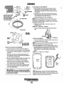
A WARNING
Exhaust gasses contain Carbon Monoxide, an odorless and
colorless gas. Carbon Monoxide is poisonous and can cause
unconsciousness and death. Symptoms of Carbon Monoxide
exposure can include:
-Dizziness
- Throbbing in Temples
-Nausea
- Muscular1lvitching
-Headache
- Vomiting
- Weakness IIIId Sleepiness -Inability to Think Coherently
IF YDU DR ANYONE ELSE EXPERIENCE ANY OF THESE SYMPTOMS,
GET OUT INTO THE FRESH AIR IMMEDIATELY. If symptoms persist,
seek medical attention. Shut down the unit and do not restart
until it has been Inspected and repaired.
WARNING
Generators Produce CARBON MONOXIDE
Regular Maintenance Required
A WARNING DECAL is provided by
WESTERBEKE and should be fixed to a
bulkhead near your engine or generator.
WESTERBEKE also recommends installing
CARBON MONOXIDE DETECTORS in the
living/sleeping quarters of your vessel.
They are inexpensive and easily
obtainable at your local marine store.
rry~~~;.~
CALIFORNIA
PROPOSITION 65 WARNING
Marine diesel and gasoline engine
exhaust and some of its constituents
are known to the State of California
to cause cancer, birth defects,
and other reproductive harm.
SAFETY INSTRUCTIONS
PREVENT BURNS - FIRE
INTRODUCTION
Read this safety lfUmual carefully. Most accidents are
caused by failure to follow fundamental rules and precautions. Know when dangerous conditions exist and take the
necessary precautions to protect yourself, your personne~
and your machinery.
The following safety instructions are in compliance with the
American Boat and Yacht Council (ABYC) standards.
A WARNING: Fire can cause injury Of death!
. • Prevent flash fires. Do not smoke or pennit flames or
sparks to occur near the carburetor, fuel line, filter, fuel
pump, or other potential sources of spilled fuel or fuel
vapors. Use a suitable container to catch all fuel when
removing the fuel line, carburetor, or fuel filters.
• Do not operate with a Coast Guard Approved flame
arrester removed. Backfire can cause severe injury or
death.
• Do not operate with the air cleaner/silencer removed.
Backfire can cause severe injury or death.
• Do not smoke or pennit flames or sparks to occur near
the fuel system. Keep the compartment and the
engine/generator clean and free of debris to ruiniruize the
chances of fire. Wipe up all spilled fuel and engine oil.
• Be aware - diesel fuel will bum.
PREVENT ELECTRIC SHOCK
A WARNING: 00 not touch AC electrical connections
while engine is running, Of when connected to shore
power. Lethal voltage Is pfesent at these connections!
•
•
•
•
•
•
•
Do not operate this machinery without electrical
enclosures and. covers in place.
Shut off electrical power before accessing electrical
equipment.
Use insulated mats whenever working on electrical
equipment.
Make sure your clothing and skin are dry, not damp
(particularly shoes) when handling electrical equipment.
Remove wristwatch and all jewelry when working on
electrical equipment.
Do not connect utility shore power to vessel's AC
circuits, except through a ship-to-shore double throw
transfer switch. Damage to vessel's AC generator may
result if this procedure is not followed.
Electrical shock results from handling a charged capadtor. Discharge capacitor by shorting terminals together.
PREVENT BURNS - EXPLOSION
A WARNING: Explosions ;fom fuel vapors can cause
injury Of death!
• Follow re-fueling safety instructions. Keep the vessel's
hatches closed when fueling. Open and ventilate cabin
after fueling. Check below for fumes/vapor before running the blower. Run the blower for four minutes before
starting your engine.
• All fuel vapors are highly explosive. Use extreme care
when handling and storing fuels. Store fuel in a well-ventilated area away from spark-producing equipment and
out of the reach of children.
• Do not fill the fuel tank(s) while the engine is running.
• Shut off the fuel service valve .t the engine when servicing
the fuel system. Take care in catching any fuel that ruight
spill. DO NOT allow any smoking, open fiames, or other
sources of fire near the fuel system or engine when servicing. Ensure proper ventilation exists when servicing the
fuel system.
• Do not alter or modify the fuel system.
• Be sure all fuel supplies have a positive shutoff valve.
• Be certain fuel line fittings are adequately tightened and
free ofleaks.
• Make sure a fire extinguisher is installed nearby and is
properly maintained. Be familiar with its proper use.
Extinguishers rated ABC by the NFPA are appropriate
for all applications encountered in this environment.
PREVENT BURNS - HOT ENGINE
A WARNING: 00 not touch hot engine parts Of
exhaust system components. A running engIne gets
very hot!
•
Always check the engine coolant level at the coolant
recovery tank.
A WARNING: Steam can cause injury Of death!
•
In case of an engine overheat, allow the engine to cool
before touching the engine or checking the coolant.
Engines & Generators
i
SAFETY INSTRUCTIONS
ACCIDENTAL STARTING
TOXIC EXHAUST GASES
A WARNING: Accidental starting can cause injury
A WARNING: Carbon monoxide (CO) is a deadly gas!
or death!
•
•
•
• Ensure that the exhaust system is adequate to expel gases
discharged from the engine. Check the exhaust system
regularly for leaks and make sure the exhaust
manifolds/water-injected elbow is securely attached.
• Be sure the unit and its surroundings are well ventilated.
Run blowers when running the generator set or engine.
• Do not run the generator set or engine unless the boat is
equipped with a functiOning marine carbon monoxide
detector that complies with ABYCA-24. Consult your
boat builder or dealer for installation of approved
detectors.
• For additional information refer to ABYC T-22
(educational information on Carbon Monoxide).
Disconnect the battery cables before servicing the engine/
generator. Remove the negative lead fust and reconnect
it last.
Make certain all personnel are clear of the engine before
starting.
Make certain all covers, guards, and hatches are
re-installed before starting the engine.
BATTERY EXPLOSION
A WARNING: Batteryexplosion can cause injury
or death!
•
Do not smoke or allow an open flame near the battery
being serviced. Lead acid batteries emit hydrogen, a
highly explosive gas, which can be ignited by electrical
arcing Or by lit tobacco products. Shut off all electrical
equipment in the vicinity to prevent electrical arcing
during servicing.
• Never connect the negative (-) battery cable to the
positive (+) connection terminal of the starter solenoid.
Do not test the battery condition by shorting the terminals
together. Sparks could ignite battery gases or fuel vapors.
Ventilate any compartment contaiuing batteries to prevent
accumulation of explosive gases. To avoid sparks, do not
disturb the battery charger connections while the battery
is being charged.
• Avoid contacting the terminals with Iools, etc., 10 prevent
bums or sparks that could cause an explosion. Remove
wristwatch, rings, and any other jewelry before handling
the battery.
• Always turn the battery charger off before disconnecting
the battery connections. Remove the negative lead first
and reconnect it last when disconnecting the battery.
A WARNING: Carbon monoxide (CO) is an invisible
odorless gas. Inhalation produces flu·like symptoms,
nausea or death!
.
• Do not use copper tubing in diesel exhaust systems. Diesel
fumes can rapidly destroy copper tubing in exhaust
systems. Exhaust sulfur causes rapid deterioration of
copper tubing resulting in exhaust/water leakage.
• Do not install exhaust outlet where exhaust can be drawn
through portholes, vents, or air conditioners. If the engine
exhaust discharge outlet is near the waterline, water could
enter the exhaust discharge outlet and close or restrict the
flow of exhaust. Avoid overloading the craft.
• Although diesel engine exhaust gases are not as toxic as
exhaust fumes from gasoline engines, carbon monoxide
gas is present in diesel exhaust fumes. Some of the
symptoms or signs of carbon monoxide inhalation or
poisoning are:
Vomiting
Inability to think coherently
Throbbing in temples
Dizziness
Headache
Muscular twitching
Nausea
Weakness and sleepiness
BATTERY ACID
A WARNING: Sulfuric acid in batteries can cause
AVOID MOVING PARTS
severe injury or death!
•
A WARNING: Rot~ting parts can cause injury
When servicing the battery or checking the electrolyte
level, wear rubber gloves, a rubber apron, and eye
protection. Batteries contain sulfuric acid which is
destructive. If it comes in contact with your skin, wash it
off at once with water. Acid may splash on the skin or
into the eyes inadvertently when removing electrolyte
caps.
...v'
or death!
•
Do not service the engine while it is running. If a
situation arises in which it is absolutely necessary to
make operating adjustments, use extreme care to avoid
touching moving parts and hot exhaust system
components .
WESTERBEKE
Engines & Generators
ii
SAFETY INSTRUCTI'ONS
•
Do not wear loose clothing or jewelry when servicing
equipment;'tie back long hair and avoid wearing loose
jackets. shirts, sleeves, rings, necklaces or bracelets that
could be caught in moving parts.
• Make sure all attaching hardware is properly tightened.
Keep protective shields and guards in their respective
places at all times.
• Do not check fluid levels or the drive belts tension while
the engine is operating.
• Stay clear of the drive shaft and the transmission coupling
when the engine is running; hair and clothing can easily
be caught in these rotating parts.
HAZARDOUS NOISE
A WARNING: High noise levels can cause hearing
loss!
•
•
•
Never operate an engine without its muffler installed.
Do not run an engine with the air intake (silencer)
removed.
Do not run engines for long periods with their enclosures
open.
A WARNING: Do not work on machinery 'when you are
ABYC, NFPA AND USCG PUBLICATIONS FOR
INSTALLING DIESEL ENGINES
Read the following ABYC, NFPA and USCG publications
for safety codes and standards. Follow their
recommendations when installing your engine.
ABYC (American Boat and Yacht Council)
"Safety Staudards for Small Craft"
Order from:
ABYC
3069 Solomon's Island Rd.
Edgewater, MD 21037
NFPA (National Fire Protection Association)
"Fire Protection Standard for Motor Craft"
Order from:
NFPA
11 Tracy Drive
Avon Industrial Park
Avon, MA 02322
USCG (United States Coast Guard)
"USCG 33CFR183"
Order from:
U.S. Government Printing Office
Washington, D.C. 20404
mentally or physically incapacitated by fatigue!
OPERATORS MANUAL
Many of the preceding safety tips and warnings are repeated
in your Operators Manual along with other cautions and
notes to highlight critical information. Read your manual
carefully, maintain your equipment, and follow all sarety
procedures.
GASOLINE ENGINE AND GENERATOR INSTALLATIONS
Preparations to install an engine should begin with a
thorough examination of the American Boat and Yacht'
Council's (ABYC) standards. These standards are a
combination of sources including the USCG and the NFPA.
Sections of the ABYC standards of particular interest are:
H-2 Ventilation
P-l Exhaust Systems
P-4 Inboard Engines
E-9 DC Electtical Systems
All installations must comply with the Federal Code of
Regulations (FCR).
~
WESTERBEKE
Engines & Generators
iii
TABLE OF CONTENTS
Installation ........... ~ ..................................................2
Parts Ide nrr
'
I Icar
IonD
rawlngs
...............................3
Introduction·.............................................................4
Serial Number Location .........................................4
Engine Troubleshooting .........................................5
Testing for Overhaul.. .............................................9
Engine.Disassembly ............................................. 10
Engine Inspection .................................................16
Assembly ...............................................................28
Thermostat ............................................................34
Actuator ...........:.....................................................34
Heat Exchanger .....................................................35
hijection Pump ..................................................36
Injection Pump Timing ......................................37 A
Governor.............................................................38
Fuel Injectors .~~ .................................................40 .
Glow Plug Testlng ..............................................41
Starter Motor .....................................................42
Raw Water Pump ...............................................46
Valve Clearance ................................................48
Air Intake .........,.................................................49
Testing Engine CompreSSion .............................49
Drive Belt Adjustment .......................................49
~
Oil Pressure .......................................................50
Actuator ....................:............................................51
Service Limits Chart.. ........................................52
Alternator Testing .............................................54
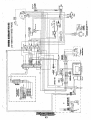
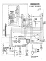
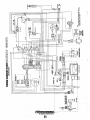
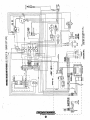
Wiring Diagrams
#54193
#54655
#53477
#54628
#54680
#52793
1O-15Kw EDT 3 Phase ..................... 57
1O-15Kw EDT 3 Phase 24V ............. 58
5.5Kw EDCI7.6-15 EDT 24V ........... 59
5.5Kw EDCI7.6-15 EDT .................. 60
5.5Kw EDCI7.6-15 EDT 24V .. ,... :... 61
5.5Kw EDCI7.6-15 EDT .................. 62
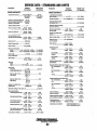
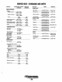
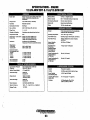
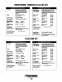
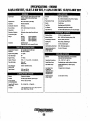
Specification Charts .......................................... 63 .
Generator .Information .......................................68
BT Generator Single Phase ...............................70
Generator FrequencyNoltage Changes ............75
Intemal W"iring D'lagram ....................................78
BT Troubleshooting 3 Phase .............................79
Voltage Regulator AdJustments ........................ 81
Torque Specifications ....................................... 82
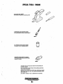
Special Tools ....................................................83
Remote Oil Filter ..................... :......................... 84
Remote Stop/Start PaneL ................................84
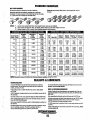
Hardware Chart .................................................85
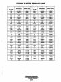
Metric Conversion Data ...................................86
WESTERBEKE
Engines & Generators
1
INSTALLATION
When installing WESTERBEKE engines and generators it is important that strict
attention be paid to the following information:
CODES AND REGULATIONS
Strict federal regulations, ABYC guidelines, and safety codes mnst be complied with
when installing engines and generators in a marine environment.
SIPHON-BREAK
For installations where the exhaust manifold/water injected exhaust elbow is close to
or will be below the vessel's waterline, provisions must be made to install iI siphonbreak in the raw water supply hose to the exhaust elbow. This hose must be looped a
minimum of 20" above the vessel's waterline. Failure to use a siphon-break when
the exhaust manifold injection port is at or below the load waterline will result in
raw water damage to the engine and possible flooding of the boat.
If you have any doubt about the .position of the water-injected exhaust elbow relative
to the vessel's waterline under the vessel's various operating conditions, install a
siphon-break.
.
NOTE: A siphon-break requires periodic inspection and cleaning to ensure proper
operation. Failure to properly maintain a siphon-break can result in catastrophic
engine damage. Consult the siphon-break manufacturer for proper maintenance.
EXHAUST SYSTEM
The exhaust hose must be certified for marine use. The system must be designed to
prevent water from entering the exhaust under any sea conditions and at any angle
ofthe vessels hull.
.
A detailed Marine Installation Manual covering gasoline and diesel
engine and generators is suppied with each unit. Additional copies
can be obtained from our website in pdf form. www.westerbeke.com.
~
WESTERBEKE
Eng/ntis & Generators
2
AVAILABLE FROM
YOUR WESTERBEKE
DEALER
\}
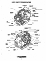
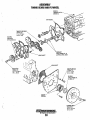
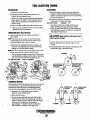
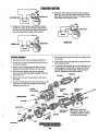
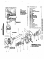
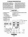
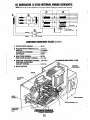
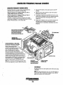
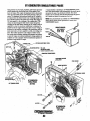
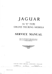
PARTS IDENTIFICATIO'N/GENERATORS
CONTROL PANEL
•
I
LEFT SIDE
CONNECTION TO
BREAK
OIL
-"or'nu ..
COOLING AIR TO AIR INTAKE
EXHAUST.
TEMPERATURE
r~t-t-:'--''-EXH,AUST ELBOW
EXHAUST
MANIFOLD
~~~-:-7"----STA,RTSOLENOID
-STAIITER MOTOR
REAR
FRONT
RAW WATER
MANIFOLD PRESSURE CAP
~:-:--=--=--=-_-_-_-_-_-_-_-..:.-~II':.F_IL_L~~BLEED
""
PETCDCK
'K\1Jk-'--~----", THERMOSTAT
ASSEMBLY
AIR INTAKE
SILENCER & FILTER
PANEL, '
INJECTION
PUMP
Ol~
FILL
BACK-ENQ,
SUMP DRAIN HOSE
"'---- IN-LINE FUEL FILTER
,BHEAKEH ' ' PREHEAT SOLIENOID'----'"
DIPSTICK
PRESSURE
SENDDR
REAR
Engines & Generators
3
FRONT
I:ustomer lilentificationCard
)
\J
A,<I,di~lqnal.aetaue4 ihfun1l\ltionllliti'.pedfic~ti(jnsareptti~
.vldM.ijtQtli\lr·~ections of·tiii$jfu\ntiJ!!,·.roY~ijtj~the· .
.li!,~erl!!llt,.~1tt11'!l(ltot, st~rter·i1l()t()r, \)!l&in'f.aqjusl!l1ents,
\\QQti11lrl1!llllP$,e,I¢;
.
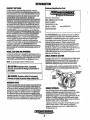
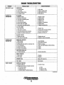
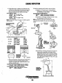
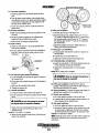
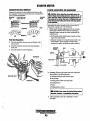
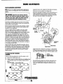
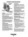
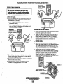
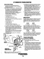
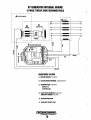
ENGINE TROUBLESHOOTING
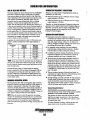
NOTE: The engine's electrical system is protected by a 20. ampere manual reset circuit breaker. The preheat solenoid is
mounted on the same bracket.
The following troubleshooting chart describes certain
problems relating to engine service, the probable causes of
these problems, and the recommendations to overcome
these problems.'This chart may be of assistance in determining the need for an engine overhaul.
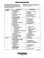
PROBLEM
HARD STARTING
LOW OUTPUT
VERIFICATION/REMEDY
PROBABLE CAUSE
LOW CRANKING SPEED
1. Engine 011 viscosity too high.
2. Run-down battery.
3. Worn battery.
4. Battery terminals loosely connected.
5. Defective starter.
6. Defective main drive section.
1. Replace engine oil with less viscous 011.
2. Recharge battery.
3. Replace battery.
4. Clean terminals and correct cables.
5. Repair or replace starter.
6. Check clutch for disengagement.
DEFECTIVE INJECTION SYSTEM
1. Air trapped in fuel passage.
2. Clogged fuel filter.
3. Low injection pressure.
4. Inadequate spray.
5. Injection pump delivering insufficient fuel.
6. Injection too early.
1.
2.
3.
4.
5.
6.
Bleed air from fuel system.
Clean or replace filter.
Adjust Injection pressure.
Clean or replace nozzle,
Repair or replace injection pump.
Adjust injection timing.
MAIN ENGINE TROUBLES
1. Low compression.
a. Incorrect valve clearance.
b. Inadequate contact of valve seat.
c. Valve stem seized.
d. Broken valve spring.
e. Compression leaks through cylinder head gasket.
t .Piston ring seized.
g. Worn piston ring and cylinder.
2. Burnt glow plug.
3. Faulty glow plug operation.
4. Incorrect governor lever posnion.
5. Governor spring out of POSITION
2.
3.
4.
5.
a. Adjust valve clearance.
b. Lap valve.
c. Replace valve and valve guide.
d. Replace valve spring.
e. Replace gasket.
t Replace piston and piston ring.
g. Overhaul engine.
Replace glow plug.
Correct lead wire connection.
Set lever to starting position.
Correct spring
lOW COMPRESSION
See HARD STARTING
INJECTION SYSTEM OUT OF ADJUSTMENT
1. Incorrect injection timing.
2. Insufficient injection.
3. Low injection pressure.
.
1. Adjust injection timing.
2. Repair or replace injection pump.
3. Check injection nozzle and adjust pressure.
INSUFFICIENT FUEL
1. Airtrapped in fuel system.
2. Clogged filter.
3. Contaminated fuel tank.
INSUFFICIENT INTAKE AIR
1. Clogged air cleaner.
1. Check and retighten connector.
2. Clean or repiace filter.
3. Clean tank.
1. Clean or repiace air ~ieaner.
(continued)
Engines & Generators
5
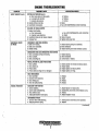
ENGINE TROUBLESHOOTING
.,
PROBLEM
LOW OUTPUT (cont.)
EXCESSIVE OIL
CONSUMPTION
EXCESSIVE FUEL
CONSUMPTION
SMOKY EXHAUST
VERIFICATION/REMEDY
PROBABLE CAUSE·
OVERHEATING
1. Low coolant level.
2. Loose V-belt.
3. Incorrect injection timing.
4. Low engine all level.
1.
2.
3.
6.
OIL LEAKAGE
1. Defective oil seals.
2. Broken gear case gasket.
3. Loose gear case attaching bolts.
4. Loose drain plug.
5. Loose oil pipe connector.
6. Broken rocker cover gasket.
7. Loose rocker cover attaching bolts.
1. Replace all seals.
2. Replace gasket.
3. Retighren bolts.
4. Retighten plug.
5. Retighten oil connections.
6. Replace gasket.
7. Retighten attaching bolts.
OIL LEVEL RISING
1. Worn piston ring ..
2. Worn piston or cylinder.
3. Incorrectly posit.ioned piston ring gaps.
4. Displaced or twisted connecting rod.
1.
2.
3.
I 4:
)
Add coolant.
Adjust or replace V-belt.
Adjust injection timing.
Add engine oil.
Replace ring.
Replace piston and rebore:cylinder.
Correct ring gap positions.
Replace connecting rod.
OIL LEVEL FALLING
1. D~fective stem seal.
2; Worn valve and valve guide.
1. Replace stem seal.
4. Replace avalve and valve,guide.
ENGINE BODY TROUBLES
1. Noisy knocking.
2. Smoky exhaust.
3. Moving parts nearly seized or excessively worn.
4. Poor compression.
5. Improper valve timing.
6. Improper valve clearance.
1. See KNOCKING.
2. See SMOKY EXHAUST.
3. Repair or replace.
4. See LOW COMPRESSION; HARD STARTING.
5. Adjust.
6. Adjust.
INSUFFICIENT INTAKE AIR
1. Air Intake obstructed.
1. Remove obstruction.
NOZZLE TRDUBLES
1. Seized nozzle.
2. Worn nozzle.
1. Replace..
2. Replace.
IMPROPER FUEL
Replace with proper fuel.
FUEL LEAKS
Find fuel leaks.
WHITISH OR PURPLISH
1. excessive engine 011.
2. Excessive rtse of oil Into combustion chamber.
a. Poor piston contact. .
b. Seized piston ring.
c. Excessive piston-to-cylinder clearance.
1. Correct oil level.
a. Check.
b. Replace or clean.
c. Replace or correct.
(continued)
E,?glnes & Generators
6
)
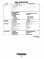
ENGINE TROUBLESHOOTING
PROBLEM
SMOKY EXHAUST (cont.)
ABNORMAL SOUND
OR NOISE
(
ROUGH OPERATION
.
VERIFICATIONJREMEDY
PROBABLE CAUSE
.
WHITISH OR PURPLISH (cont.)
d. Worn valve stem and valve guide.
e. Low engine oil viscosity.
I. Excessive oil pressure.
3. Injection timing is too late.
4. Insufficient compression.
d. Replace.
e. Replace.
I. Correct.
3. Adjust.
4. See LOW COMPRESSION; HARD STARTING.
BLACKISH OR DARK GRAYISH
1.Engine body troubles.
a. Poor compression.
b. Improper valve clearance.
2. Insufficient intake air (air cleaner clogged).
3. Improper fuel.
a. See LOW COMPRESSION; HARD STARTING.
b. Adjust.
2. Clean air cleaner.
3. Replace wfth proper fuel.
CRANKSHAFT AND MAIN BEARING
1. Badly worn bearing.
2. Badly worn crankshaft.
3. Melted bearing.
1. Replace bearing and grind crankshaft.
2. Grind crankshaft.
3. Replace bearing and check lubrication system.
CONNECTING ROD AND CONNECTING ROD BEARING
1. Worn connecting rod big end bearing.
2. Worn crankpin.
3. Bent connecting rod.
1. Replace bearing.
2. Grind crankshaft.
3. Correct bend or replace.
PISTON, PISTON PIN, AND PISTON RING
1. Worn cylinder.
2. Worn piston pin.
3. Piston seized.
4. Piston seized and ring worn or damaged.
1.
2.
3.
4.
VALVE MECHANISM
1. Worn camshaft.
2. Excessive valve clearance.
3. Worn timing gear.
4. Worn fan pulley bearing.
1. Replace.
2. Adjust.
3. Replace.
4. Replace.
INJECTION PUMP SYSTEM
1. Uneven injection.
2. Control rack malfunctioning.
3. Worn delivery valve.
4. Inadequate Injection nozzle spray.
1.
2.
3.
4.
GOVERNING SYSTEM
1. Governor lever malfunctioning.
2. Fatigued governor spring.
1. Check governor shaft and correct operation.
2. Replace.
Rebore cylinder to oversize and replace piston.
Replace piston.
Replace piston and rebore cylinder.
Replace piston and rings.
Adjust injection orreplace parts.
Disassemble, check and correct Injection pump.
Replace.
Replace Injection nozzle.
(continued)
..,... WESTERBEKE
EngInes & Generators
7
ENGINE TROUBLESHOOTING
PROBLEM
KNOCKING
.'
PROBABLE CAUSE
ENGINE KNOCKS WITHOUT MUCH SMOKE
1. Main engine troubles.
a. Overheated cylinder.
b. Carbon deposits in cylinder.
2. Too early'lnjectlon timing.
3. Too high Injection pressure.
4. Improper fuel.
KNOCKING WITH DARK SMOKE
1. Poor compression.
2. Injection pump malfunctioning •.
3. Improper nozzle.
a. Poor spray.
b. Poor chattering.
c. After-injection drip.
d. Nozzle needle valve seized.
VERIFICATION/REMEDY
a. See OVERHEATING; LOW OUTPUT.
b. Clean.
2. Correct.
3. Correct.
4. Replace with proper fuel.
1. See LOW COMPRESSION; HARD STARTING.
2. Adjust/Repair
a. Clean or replace nozzle.
b. Repair or replace nozzle.
c. Repair or replace nozzle.
d. Replace.
INTERMITTENT
EXHAUST SOUND
1. Fuel filter clogged.
2. Fuel pipe sucks air.
3. Water mixed in fuel
1. Clean or replace.
2. Retighten pipe jOints or replace pipe.
3. Replace fuel.
OVERHEATING
1. V-belt slackening or slippery with 011.
2. Damaged water pump.
3. Lack of coolant.
4. Low oil level or poor oil quality.
5. Knocking.
6. Moving parts seized or damaged.
7. Defective thermostat.
1. Adjust, replace or clean.
2. Replace.
3. Add.
4. Add or change.
5. See KNOCKING.
6. Replace.
7. Replace.
1. Worn Bearings.
2. Relief valve malfunction.
3. Clogged 011 cooler.
4. Diesel dilution of the 011.
1. Engine overhaul replace bearings.
2. Overhaul 011 pump.
3. Repair.
4. Injection pump repair.
LOW DlL PRESSURE
)
LCD DISPLAY FAULTS
(continued)
Engines .&. Generators
8
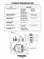
ENGINE TROUBLESHOOTING
LCD DISPLAY FAULTS,
PROBLEM
LCD DISPLAY DOES
NOT ILLUMINATE
LOW OIL PRESSURE
HIGH COOLANTTEMPERATURE
HIGH EXHAUSTTEMPERATURE
BATTERY VOLTAGE
GENERATOR FREQUENCY
overspeed (steady LED)
Underspeed (flashing LED)
LED DISPLAY EDGES
TURN PINK
WAITING FOR ECU
1.
2.
3.
4;
PROBABLE CAUSE
Check ballery.
20 amp breaker off.
Loose display connection.
1 amp fuse blown (faulty) •.
1.
2.
3.
4.
1. Oil level low/oil leak.
2. Lack of oil pressure
3.
4.
5.
1.
2.
3.
Ground connection.
Faulty control module (ECU).
Faulty oil pressure sensor.
Check system coolant level.
Sea water pump.
Check water pump drive belt.
4. Faulty temperature sensor.
5. Ground connection.
6. Faulty control module (ECU).
1. Check sea water flow.
2. FaultY exhaust temperature switch.
3. Ground Connection.
4. Faulty control module (ECU).
5. Sea water pump.
6. Faulty fire suppression system.
1. Check alternator drive belt.
2. Check charge voltage.
3. Che,ck battery connections.
4: Faulty control module (ECU).
1. Check engine speed.
2. Check fuel supply.
3. Amperage load.
4. Crank cycle with no start
(underspeed fault)
1. Compartment ambient temperature
too high.
1.
2.
3.
4.
5.
ECU and LCD display not compatible
Loose cable connection.
Panel DC breaker OFF.
Blown 8 amp fuse.
Terminating ReSistors.
6. Battery Voltage to ECU.
VERIFICATION/REMEOY
Ballery on.
Turn breaker on.
Check all cable connections.
Check/replace. Determine cause
1. Check oil level. add oil and repair leaks.
2. Test oil pressure. If OK. test oil pressure sendor. inspect
oil filter. inspect oil pump.
3. Check ground connection.
4;' Inspect all the plug connections/replace.
5. Check sensor/replace.
1. Add coolant. Check for leaks.
2. Inspect Impeller/pump/replace.,
3. Adjust belt tension. replace belt.
4. Check sensor/replace.
5. Check ground circuit.
6. Check plug connections/replace.
1. Inspect thru hull filling. hose and strainer. Correct
as needed.
2. Test/replace.
3. Check ground circuit.
4. ,Check plug connections.
5. Inspect impeller/replace.
6. BY'pass system/check.
1; Adjusttensionireplace if worn.
2. Check excitation. Replace/repair alternator
3. Check +and· cables from ballery to engine.
4. Check plug connections/replace.
1. Check speed selling.
2. Inspect filters/replace filters. Test fuel pump operation.
3. Check +and· cables from ballery to engine.
4. Check cause for no start.
1. Ventilate compartment.
Nola: Heat will often change the c%r of an LCD
display. This will not effect the operation of the engine.
1. Check compatibility with Westerlink or NMEA.
2. Check all cable connections.
3. Turn ON. check DC vollage across breaker.
4. Check/replace fuse. Check DC voltage across fuseholder
5. Check alilerminating resislors ara In place. 120 ohm
per resister measured across pin #4 and #5.
6. Check between pins P2-24 and P2-25. P2 ECU plug
unplugged from ECU. Power turned ON. If voltage Is
present. ECU is faulty.
... WESTERBEKE
Engines & ,Generators
SA
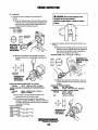
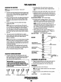
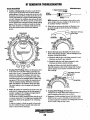
TESTING FOR OVERHAUL
HOW TO DETERMINE ENGINE OVERHAUl. PERIOD
Cause of Low Compression
Generally, the time at which an engine should be overhauled
is determlned by various conditions such as lowered engine
power outpu~ decreased compression pressure, and increased
fuel and oil consumption. The lowered engine power output
is not necessarily due to trouble with the engine iiself, but is
sometimes caused by injector nozzle wear or injection pump
wear. The decrease in compression pressure is caused by
many factors. It is, therefore, necessary to determlne a cause
or causes on the basis of data produced by periodic
inspection and maintenance. Oil analysis on a seasonal basis
is a good means of monitoring engine internal wear. When
caused by wom cylinders or piston rings, the following
symptoms will occur:
1 Low engine power ontput
2 Increased fuel consumption
3 Increased oil consumption
4 Hard engine starting
5 Noisy engine operation
OVERHAUL CONDITIONS
Compression pressure tends to increase a little in a new
engine until piston rings and valve seats have been broken in.
Thereafter, it decreases gradually with the progress of wear
. of these parts.
When decrease of compression pressure reaches the repair
limit, the engine must be overhauled.
The engine requires overhaul when oil consumption is high,
blowby evideut, and compression values are at minimum or
below. Engine compression should be 30 kglcm', 427 psi at
290 rpm. Tlje maximum difference between cylinders must
not exceed IO%.
Minimum compression of 384 psi (27 kglcm') is an indication
for overhaul.
DISASSEMBLY
1. Before disassembly and cleaning, carefully check for
defects which cannot be found after disassembly and
cleaning.
2. Drain water, fuel and oil before disassembly.
3. Clean or wash the engine exterior.
4. Do not remove or disassemble the parts that require no
disassembly.
5. Perform disassembly in a proper order using proper tools .
Keep disassembled parts in order. Apply oil when
necessary. Take special care to keep the fuel system parts
from intrasion of dust and dirt.
6. Parts must be restored to their respective components from
which they were removed at disassembly. This means that all
parts must be set aside separately in groups, each marked for
its component, so that the same combination or set can be
reproduced at assembly.
7. Pay attention to marks on assemblies, components and
parts for their positions or directions. Put on marks, if
necessary, to aid assembly..
8. Carefully check each part or component fore any sign of
faulty condition during removal or cleaning. The part will
tell you how it acted or what was abnonnal about it more
accurately during removal or cleaning.
These symptoms often appear together. Symptoms 2 and 4
can result also from excessive fuel mjection, improper injection timing, and wear of plugs and nozzles. They are caused
also by defective electrical devices such as the battery,
. alternator, starter and glow plugs. Therefore it is desirable to
judge the optimum engine overhaul time by the lowered
compression pressure caused by warn cylinders and pistons
plus increased oil consumption. Satisfactory combustion is
obtained ouly under sufficient compression pressure. If an
eugine lacks· compression pressure, incomplete combustion
of fuel will take place even if other parts of the engine are
operating properly. To determlne the period of engine overhaul, it is important to measure the engine compression
pressure regularly. At the same time, the engine speed at
which the measurement of compression pressure is made
should be checked because the compression pressure varies
with engine rpm. The engine rpm can be measured at the
front end of the crankshaft.
NOTE: To test engine compression see the ENGINE
ADJUSTMENT section of this manual.
ASSEMBLY
OVERHAUL CONDITIONS
1. Wash all parts, except for oil seals, O-rings, rubber sheets,
etc., with cleaning solvent and dry them with pressure air.
2. Always use tools that are in good condition and be sure
you nnderstand how to use them before perfonning any
job.
3. Use only good quality lubricants. Be sure to apply·a coat
of oil, grease or sealant to parts as specified ..
4. Be sure to use a torque wrench to tighten parts for which
torques are specified.
5. Ant time the engine is assembled, new gaskets and
a-rings must be installed.
When rebuilding the engine, the alternator should be cleaned
and inspected. The housing can be wiped off with a solvent
and the altemator termlnal studs should be cleaned with a
wire brush. Make certain the studs are tight and clean the
wiring connections that connect to the wiring harness.
Turn the rotor pulley by hand. It should tum smoothly.
Depending on when the alternator was last serviced. the
brushes may need replacing. If the alternator is at all suspect,
send it to a service shop for testing and overhaul.
For additional information on alternators refer to the
ALTERNATOR TROUBLESHOOTING in this manual.
-.,.y:
WESTERBEKE
Engines & Generators
9
)
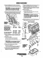
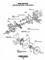
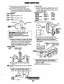
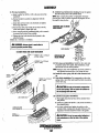
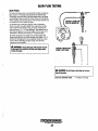
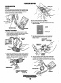
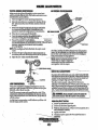
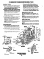
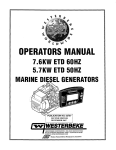
ENGINE DISASSEMBLY
GENERATOR
ENGINE DISASSEMBLY
Disconnect the AC wiring and unplug the engine's DC .
wiring harness at the generator control panel. Remove the
battery cables from the engine and tape over the terminals.
NOTE: Label any lines, hoses or cables as you separate them.
Separate the exhaust hose at the water injected elboW and
disconnect the fuel supply an<j return lines.
Drain the engine oil and the coolant from the engine.
Carefully support and then unbolt the generator backend
from the engine. See SPECIAL TOOLS in this manual.
Additional generator information will be found in the
GENERATOR section of this manual.
Take the following precautions:
• Oean the exterior of the engine of any deposits of
PROPULSION ENGINE
Switch off the batteries and disconnect the battery cables
from the engine and tape over the terminals.
Drain or pump out all the engine oil and drain the coolant
from t1Je engine and engine hoses.
Unplug the instrument panel wiring harness. Drain the
ttansmission fluid and the transmission oil cooler hoses,
Detach the ojl' cooler hoses and unbolt the transmission from
the engine.
NOTE: Label any lines, hoses or cables tis you separate them.
(
BLOCK
COOLANT
DRAIN PLUG
NOTE: Acoolant
hose may be on this
boss in. lieu of the
plug. Remove the hosa·
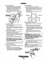
If the transmission is not being rebuilt it should be visually
inspected. Flush out and pressure test the oil cooler and
replace the coolant hoses. Inspect and lubricate the gear sbift
linkage and the propeller shaft coupling. Clean and repaint
the transmission and cbange the transmission fluid.
For transmission service and maintenance reter to your
ttansmission manual. To rebuild a transmission contact your
WES1ERBEKE dealer or an authorized transmission service
dirt and oil.
• Be careful not to damage the disassembled parts.
• Arrange parts in the order of disassembly. Mark or
label parts as needed to insure proper mating and
reassembly. Keep parts clean. .
• Mount the engine on a suitable engine stand for
disassembly.
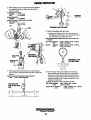
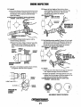
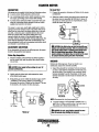
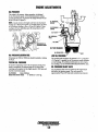
With the lrljnsmission separated from the engine, begin the
following step by step procedure to disassemble the engine.
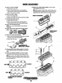
l.Remove the transmission damper plate from the
engine flywheel.
2. Remove the engine oil cooler and uil hoses. Note oil
hose connections from the oil cooler to the engine.
3. Remove the engine heat exchanger. If possible, leave
one end of each hose connected to the part being removed.
4. Remove the bell housing and the circuit breaker!
preheat solenoid monnting braeket.
5. Remove the engine back plate.
6. Remove the start motor, drive belt and the alternator.
Label the wires and cables.
7. Remove the engine monnted raw water pnmp,
complete with its adapter mounting plate. See RAW
WAT.l?R PUMP for parts breakdown.
S. With the hoses disconnected, remove the thermostat
housing and housing gasket, leaving the temperature
sender in place.
9. Remove the coolant circulatblg pump. Refer to
COOlANT CmCULATING PUMP ASSEMBLY.
lO.Remove the air intake silencer and the intake manifold.
1l.Reinove the oil 61ter and the mounting bracket from the
engine block.
l2.Unbolt the elbows and remove the exhaust manifold in
its entirety.
l3.Remove the fuel injection pump. Disconnect the fuel
injection pipes and fuel leak-off pipe from the fuel injection
PU\IlP and nozzles,
NOTE: Put plugs or caps on the openings of the injection pump
and nozzle connectors. Golf tees work well as plugs.
l4.Remove the fuel injection nozzle.. Loosen the fuel
injection nozzles with a wrench. Remove the nozzles and
gaskets from the cylinder head.
.
center:.
DAMPER PLATE
BOLTS
.
NOTE: Remove the gaskets from the cylinder head with a
· gasket scraper. Discard the gaskets.
DAMPER
. PLATE
'"
Engines & Generators
10
ENGINE DISASSEMBLY
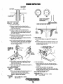
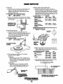
15. Remove governor assembly.
a. Remove the tie rod cover.
23. Remove the cyfuider head assembly. Lift the cylinder
head straight up with a hoist.
ii'·····. ," .
. . FUEL
,
,.
•
)
NOTE: if the gasket is seized and the cylinder hedd cannot
b. Remove the spring from the tie rod with pliers to
disconnect the tie rod from t\1e fuel injection pomp.
c. Remove the governor assembly.
16. Remove governor weight.
a. Remove the sliding sleeve.
b. Remove the sliding sleeve shaft and governor weigbts.
17. Fuel injection pump removaL
a. Remove the tie rod cover.
b. Remove the spring from the tie rod with pliers to
disconnect the tie rod from the fuel fujection pomp.
18. Remove the fuel injection pump.
NOTE: Keep a record of the thickness of the shims for
in11tallation.
.
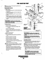
19. Remov~ ..the pressure relief valve from
blOCk.•
LOCATEiiJusr'
." . .
\ 'UNDER THE .
be separated from the cylinder block, tap around the thick
Siile1WrtiOI:! of the cylinder head with a plastic hammer.
. ORDER OF DISASSEMBLY
'
: PUMP DN THE
BLGCK.' ;
.' '.ENGINE
.. - .
.
20. Remo~e th~r;;~ker shaft assembly.' ',' .
a. Remove the bolts that hold the rocker stays in position
and remove the rocker shaft assembly. .
b. Remove the valve caps.
)
"'iIIISASSEMIBLlIIG THE
•ROCKER SHAFT ASSEMBLY
21. Disassemble the rocker shaft assembly. Put identification on each rocker arm as to its location on the rocker
shaft.
22. Remov~ the .cylinder head bolt. Loosen the cylinder
head bolts in two or three steps in the sequence shown.
. NiltE: it ~ny p~ris on the g,iinde~ head are faUlty, check
the cylinder head bolts for tightness with a torque wrench "
before loosening them.
.
G9
07
$3
.12
.5
.10"
.14
1118
.13
".3'tYEINDER .
CYLINDER HEAD BOLT LOOSENING
SEQUENCE
11
ENGINE DISASSEMBLY
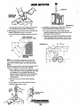
27. Remove the rear plate.The rear plate is doweled in
position. Pull the plate as straight as possible when
removing it.
28. Remove the oil seal case. Remove the bolts that hold
the oil seal case in position. Remove the case from the
ey linder blC)ck with a screwdriver.
VALVE SPRING '
REMOVAL
A CAUTION: Do not caUSB damage to the oil
seal.
29. Remove the tappet. Remove the tappets from the
cylinder block with a valve push rod.
'
• 24: Removethe valve and valve spring.'
a. Compress the valve spring with a valve lifter and
, remove the valve lock.
b. Remove the retainer, spring and valve.
NOTE: The tappets will fall into the 'oil pa~ if the camshaft
is removed before the tappets are removed.
REMOVING THE
CRANKSHAFT PULLEY
NOTE: The valves, retainers, springs and valve lock.! must '
be set aside separately in' groups, each tagged for
cylinder./lumber, for correct installation.
25. Remove the valve stem se31s with pliers.
NOTE: Do not reuse the valve stem seals.
(
", 26. Remove the flywheei.
a. Have someone hold the crankshaft pulley with a
wrench to prevent the flywheel froin rotating.
b. Remove one of the bolts'that hold the flywheel
in position.
c. Install a safety bar (MI2 x 1.25) into the threaded hole
in the flywheel from which the bolt was removed.
Remove the remaining bolts.
. d. Hold the flywheel by hand and withdraw it from the
crankshaft. Joggling the flywheel back and forth to
facilitate removal.
, ORDER OF DISASSEMBLY
,
BAR
, 30. Remove the crankshaft pulley.
B. Install two safety bars (MI2 x 1.25) into the threaded
,holes in the rear end of tile .crankshaft. Put a bar
, "between the safety bars to hold the crankshaft to
prevent it from rotating.
b. Remove the crankshaft pulley.
A
WARNING: When rBmoving the crankshaff
,pulley, be pmpared to stop the Job in case the bar
slips oft the crankshaff to prevent injury.
A WARNING: When removing the flywheel, wear '
heallY gloves to avoid hand injury.
,
12
ENGINE DISASSEMBLY
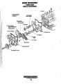
TIMING GEARS
ORDER OF DISASSEMBLY
NUMBERS INDICATE THE ,
. SUGGESTED ORDER OF
DISASSEMBLY. .
.14 INJECTION
PUMP CAM~I:IAFT
a. IDLER
GEAlf
REMOVE 9 THRU 11
AS AN ASSEMBLY
·12 FUEL iNJECTION"
1.;J~r.'nINu.
. 'PUMP CAMSHAFT
'REMOVE 12 THRU 14
AS AN ASSEMBLY .
CAMSHAFT'
\
/
7TIMING GEAR CASE'
Q t:RANKSHIIFT PULLEY
i
'....v'
WSTERBEKE
Englnes-& Generators
13
ENGINE DISASSEMBLY
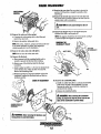
31. Remove the timing gear case. Remove the bolts that
hold the timing gear case in position and remove the case.
37. Remove the oil pump. Remove the bolts that hold the oil
pump to the cylinder block and remove the pump.
38. Remove tIie front plate. Remove four bolts that hold the
front plate in position, Tap the plate lightly with a plastic
hammer to separate the gasket.
39. Remove the oil pan.
a. Turn the engine upside down.
b. Tap the bottom comers of the oil P!'ll with a plastic
hammer to remove the oil pan.
A WARNING: The front plate Is bolted Inside the
timing gear case. Do not attempt to remove this
plate along with the timing gear case by tapping.
32. Timing gear backlash measurement. Measure the back·
lash of each gear and keep a record fOr correct measure.
ment.
if the backlash exceeds the limit.
A
CAUTION: Do not attempt to pry off the oil
pan by Inserting a screwdriver or a chisel between
the 011 pan and the cylinder block. Damage to the
oil pan can be the result.
40. Remove the oil screen. Loosen the nut that holds the oil
screen in position and remove the screen.
.\ ORDER OF DISASSEMBLY
MEASURING' ,
TIMING GEAR
BACKLASH
8~~
9---.~,u
TIMING GEAR BACKLASH
STANDARD.
LIMIT
CRANKSHAFT GEAR AND IDLER
GEAR· IDLER GEAR AND
CAMSHAFT GEAR· IDLER
GEAR AND FUEL INJECTION
PUMP CAMSHAFT GEAR
CAMSHAFT GEAR/P.T.O. GEAR
0.0016·· 0.0047 In
(0.04' 0.12mm) ..
0.01.18 In
(0.30mm) .
FUEL INJECTION PUMP CAMSHAFT
GEAR AND OIL PUMP GEAR
0.0028· 0.0079 In
0.0118 In
(0.07' 0.20mm) (0.30mm)
10
6
0.0031 ·0.0075'10 .. 'o~dm In
(0.08·0.19mm)
(0.30mm)
33. Remove the idler gear. Th remove the idler gear, rotate
the gear in a direction of the helix of the teeth to pull it
out of mesh.
34. Remove the camshaft.
a. Remove the bolts that hold the thrust plate.
b. Pull the camshaft out of the cylinder block.
t-UlJ,----5
.
11----i~
4
I
~
3~
_
~
... .... . . Ji .•....
NUMBERS INDICATE THE.
SUGGESTED OROER OF
r------------------, . DISASSEMBLY
A CAUTION: Do not cause damage to the lobes
or bearing Joumals when removing the camshaft
35. Remove the fuel injection pump camshaft.
a. Remove the stopper bolt.
b. Thp the rear end of the camshaft with a copper bar to
push it out of the front side of the cylinder block.
36. Remove the gear ( when required). To remove the
gears from the camshafr and fuel injection pump
camshafr, use an arbor press.
.C'(LlNIIERiii.IICK
CRANKSHAFT
PISTONS AND
OIL PAN' .
""""'1"<'--1
Englnes-& 'Gene;ators
14
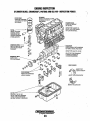
ENGINE DISASSEMBLY
41. Thrust clearance measQrement for connecting rod big
end. Install the connecting rod to its crankpin and tighten
the cap nuts to the specified torque. Measure the thrust
clearance with a feeler< gauge. If the clearance exceeds the
limi~ replace the connecting rod.
THRUST CLEARANCE
STANDARD: 0.0039' 0.0138 in
LIMIT:
0.0197 in to.50mrn)
46. Remove the crankshaft.
A CAUTION: Do not cause damage to the'
bearings.
NOTE: Put identification on each main bearing as to its
location in the engine.
MEASURING·
THRUST CLEARANCE •
FOR CONNECTING
ROD BIG END
42. Remove the connecting rod cap.
a. Lay the cylinder block on.its side.
b. Put identification on each connecting rod and cap
combination as to its location in the engine.
c. Remove the caps.
43. Remove the piston.
a. Thrn the crankshaft until the piston is at top center.
b. Push the piston and connecting rod away from the
crankshaft with the handle of a hanuner until the
piston rings are above the cylinder. Remove the piston
and connecting rod. Repeat steps a and b for the
removal of the other pistons.
.
47. Separate the piston from the connecting rod.
a. Use Piston Pin Setting Tool to separate the piston from
the connecting rod.
b. Insert the push rod of the tool into the bore in the
piston for the piston pin and, using an arbor press,
remove the piston pin.
c. Also use the Piston Pin Setting Tool to install the·
connecting rod to the piston.
.
A CAUTION: Do not attempt to remove the
piston pin by tapping. Replace any piston pin which
. requires a<greater force for removal.
REMOVING THE
PISTON
___'PU!;" ROD TOOL
<CONNECTING ROD
44. Measuring the crankshaft end play. Set a dial indicator
so that it will touch the end of the crankshaft and measure
the end play. If the end play exceeds the limit, replace the
flanged bearing.
PISTON
CRANKSHAFT END PLAY
STANDARD: 0.00197· 0.00689 In (0.050· 0.175mm)
LIMIT:
0.01969 In (0.500 mm)
45. Remove the main bearing cap•
•• <Lay the cylinder block with its bottom (oil pan).
side<up.
b. Remove the bolts that hold the main bearing caps in
position. Remove the caps.
.
c. Remove the frcint and rear bearing caps with a sliding
hanuner.
15
"CONNEC:TlNG ROD
)
ENGINE INSPECTION
1. Cylinilei:' head. Usil1g a he~vy accurate straight edge and
a feeler gauge, check the bottoril face for warpage in three
positions; lengthwise, two crosswise and two widthwise as
shown in the ilfustration. If warpage exceeds the limit,
refaee. ihe bottom face with a surface grinder.
CYLINDER HEAD'AND VALVE MECHANISM
CHECK
THREADS
CHECK OIL HOLES FOR CLOGGING
WARPAGE - CYLINDER HEAD IiOTTOM FACE
STANDARD
0.0020 In (0.05mm) MAXIMUM
LIMIT'
0.00391n ((0.10mm)
' " CHECK FOR WEAR . ... ' .
IN BORE
.
€.\l.'~-INlfpEl:TFOR WEAR
CLOGGED OIL HOLES
~INSI~EClr~N~ THE
CYLINDER HEAD
BOnDMFDR
WARPAGE'
INSPECT FOR.
IIDd
2. Rocker arms
rockershaft. Measure the bpre in the
roclier arm for the rocker shaft and the di!lljJ.eter of the
. rocker shaft to find the clearanee between the arm and the
shaft. If the clearan~e has reached the limit, replace the
rocker arm. If it exceeds the limit, replace both arm and
shaft.
INSPECT AND .
TEST SPRING
-INSIPECT FOR CRAcKS, OIL
(iUU,lAIV I LEAKS. CLEAN
OFF SCALE AND CARBON
DEPOSITS
BORE IN ROCKER ARM FOR SHAFT
STANDARD
0.74449 - 0.74527 In (18.910 -18.930mm)
DIAMETER OF SHAFT FOR ARM
STANDARD
0.74331 - 0.74401 In (18.880 -18.898mm)
CLEARANCE BETWEEN ROCKER ARM AND SHAFT
STANDARD
0.00047 - 0.00197 in (0.012 - 0.050mm)
LIMIT
0.00787 (0.200mmr
CHECK FOR GALLING
AND WEAR
k _ _-INSPECT FOR RIDGES
. ORDAMAGE
INSPECTFO
.. WEAR AND
CONTACT
CHECK ENDS
FOR WEAR
AND DAMAGE
MEASURING ROCKER ARMS
AND ROCKER SHAFT
~---INSPECT FOR
BEND
Engines & Generators
16
ENGINE INSPECTION
3. Valve springs. Check the Squareness and free length. If
the'squareness andlor free length exceeds the limit,
replace the spring. .
VALVE SPRING FREE LENGTH
STANDARD
1.85 In (47mm)
LIMIT
1.81 in (46mm)
SPRING SQUARENESS
STANDARD
1.5' MAXIMUM
SPRING TEST FORCE· LENGTH UNDER TEST FORCE
(1.54 in (39.1mm)
STANDARD
30.6 ± 1.5 Ib·n
13.9 ± 0.7 Kg·f
LIMIT
·15%
MEASURING.
DIRECTIONS
CHEJ:KING VALVE STEM WEAR
5. Valves, valve guides and valve seats.
a. Measure the diameter of the valve stem as shown in
the illustration. If the stem is woni beyond the limit, or
it is abnormally worn, replace the valve.
VALVE STEM DIAMETER (NORMAL SIZE 0.260 in (6.6mm) INLET ANO
. EXHAUST)
INlET VALVE: STANDARD
0.25846 - 0.25905 In (6.565 - 6.580mm)
LIMIT
0.25591 In (6.500mm)
STANDARD 0.25709 - 0.25787 in (6.530 - 6.550mm)
EXHAUST:
0.25591 in (6.500mm)
LIMIT
. : MEASURING 1.0. OF
. THE VALVE GUIDE
l
.:. 1------
4: V.d~~ p~h ...;;.i.: U,;j~g-V=-blocks and a dial indicator,
check for bend. If the:.bend yxeeeds the limit, replace the .
push rod.
BEND (DIAL INDICATOR READING) OF VALVE PUSH ROD
LIMIT
0.012 in (0.3mm) Mj\](I.iIIUM
.
INSPECTING THE
BEND OF THE PUSH
ROD
b. The valve guide wears more rapidly at its both ends
than any other parts. Measure the bore in the guide for
the stem at its ends with an inside micrometer caliper
to find the clearance between the stem and guide. If the
clearance exceeds the limit, replace the guide or valve
whichever is badly worn.
CLEARANCE BETWEEN THE VALVE STEM AND VALVE GUiDE
INLET VALVE: STANDARD
0.008 - 0.0020 In (0.02 - 0.05mm)
LIMIT
0.0039 in (0.10mm)
EXHAUST VALVE: STANDARD
0.0020 - 0.00336 In (0.05 - 0.085mm)
LIMIT
0.0059 in (0.15mm)
''''''WESTERBEKE
I Engines & Generators
17
ENGINE INSPECTION '
0.39±,0.02o In
(io±0.5 mm)
VALVE
GUIDE~t7r..."._-,·_......;t,-'_"_"
--}
CYLINDER HEAD '
GOOD
e
:.
'"
CONTACT MUST BE UNIFORM
AROUND THE COMPLETE
CIRCUMFERENCE
.e
HEIGHT TO THE TOP OF THE VALVE
NORMAL SIZE
0.39 in (lOmm)
(
.
ill
VALVE AND VALVE SEAT CONTACT
c. Valve guide replacement.
(1) Remove the guide from the cylinder head by
pushing it with a tool and an arbor press from the
bottom side of the head.
(2) Install a new guide into the cylinder head by
pushing it with an arbor press from the upper side
of the head until the specified height to the top of
the guide is obtained.
(3) Insert a new valve into the guide and make sure the
valve slides in the guide freely.
(4) Mter the valve guide has been.replaced, check the
valve contact with its seat.
(5) Put a small amount of Prussian blue or read lead on
the valve face. Hold the valve with a valve lapping
tool (commercially available) and press it against
, the seat to check its contact.
6. Valve refacing.
a. Set the valve n;facer at an angle of 45° and grind the
valve.'
'
b. The valve margin must not be less than the limit. If the
margin seems to be less than the limit when the valve
is refaced, replace the valve.
LAPPING THE
VALVE IN THE
SEAT
/
(6) The width of contact must be uniform all the way
7. Valve seat refacing.
a. Before refacing the valve seat, check the clearance
around both seat and valve. If the contact is bad,
reface the valve and seat
(7) If the valve margin (valve lip thickness) exceeds the
limit, replace the valve.
between the valve and guide, and replace the guide if
necessary,"
b. Curthe valve seat with a valve seat cutter
(commercially availlible), or grind it with a valve seat
grinder, and finish the width of valve seat and the angle
of seat face to the correct values.
VALVE MARGIN (LIP) THICKNESS
STANDARD
0.039 In (l.omm)
LIMIT
0.020 In (0.5mm)
'(8) If the valve sinkage (the dimension from the top of
a: closed valve to the face of cylinder head)
,exceeds the lintit, recondition the valve seat or
replace the cylinder head assembly.
VALVE SINKAGE'
STANDARD
LIMIT
0.020 ± 0.0098io (0.5
0.05910 (1.5mm)
ANGLE OF SEAT FACE: STANDARD 45"
WIDTH OF VALVE SEAT
STANDARD
0.051 - 0.071 In (1.3 -1.8mm)
LIMIT
0.098 In (2.5mm)
± 0.25mm)
Engines '& Generators
18
ENGINE INSPECTION
I-L.__ '\UU'\U BAR
L _ _ COMI~USTIIONJET
c. After refacing the valve seat, put lapping c.ompound on
the valve face and lap the valve in the valve seat.
8. Valve lapping. Be sure to lap the valves in the seats after
refacing or replacing the valves or valve seats.
a. Put a small amount-of lapping compound on the valve
seat.
OF VALVE SEAT
• 0.071 IN (1.3 • 1.8MM)
9. Combustion jet replacement. Replace the combustion
jets only when they are cracked or defective.
a. To remove the jet, inseit a 6mm (O.2Sin) diameter
round bar through the bore in the cylinder head for the
glow plug and tap around the jet.
b. To install a new jet, put the jet in position in the head
with its tangential orifice in alignment with the center
of the main chamber and tap it with a plastic hammer.
COMBUSTION JET'
\
j
.
-
NOTE: Do not put lapping compound on th~ valye stem.·
Use a lapping compound of 120 to 150 meshfor'initial
lapping and a compound offiner than 200 mesh for finish
lapping.
Mixing the compound with a sl'fIIlll amount of engine oil will
help put the compound on the valve face uniformly.
b. Using a lapping tool, hold the valve against the seat and
rotate it only a part of a turn, then ralse the valve off its
seat, rotating it to a new position. Press the valve
against the seal for another part of a turn. Repeat this
operation until the compound wears and loses its
cutting property.
c. Wash the valve and valve seat with dry c1earting
solvent.
d. Apply engine oil to the valve and lap it in the seat.
e. Check the valve face for contact.
LAPPING
VALVE IN
SEAT
APPLYING LAPPING
COMPOUND
Engines -& Generators
19
ENGINE INSPECTION
TIMING GEARS AND FLYWHEEL· INSPECTION POINTS
TAPPET
INSPECT FOR
,,~n
__
GASKET
CAI\lSHAFT
BEARING
CHECK FOR NOlllE (S'PINAIING)
AND WEAR.
GEARS
CHECK TEETH
WEAR. BURRS. OR CHIPS
CHECK FOR BEND OR DAMAGE TO THE LOBES
(
r-----:-----"TINII.A GEAR CASE
iii",;",.., <(io CRACKS/DISTORTION
GASKET'
CRANKSHAFT
INSPECT BELT: ':':"~:.-
FOR OAMAGE/AGING
. FLYWHEEL
CHECK CONTACT FACE FOR SCORING
OR RlOGES. CHECK GEAR FOR OA~'AGE'-- _ _
OR WEAR TO TEETH.
-=-_--.i
Engines & Generators
20
ENGINE INSPECTION
10. Camshaft
a. Measure the diameter of the joUrnal and the bore in the
bushing for the shaft to find the clearance as shown in
the illustration. If the clearance exceeds the limit,
replace the bushing.
CLEARANCE BETWEEN THE CAMSHAFT JOURNAL AND BUSHING
STANDARD 0.0059 In (0.15mm)
(3) Measure the lobe height and base circle as shown
in the illustration. Subtract the baSe circle' from the
lobe'height to find the lobelift. If the lobe lift
exceeds' the limit, replace the camshaft.
.
LOBE HEIGHT OF CAMSHAFT
STANDARD 1.4063 in (35.72mm)
LIMIT
1.3669 in (34.72mm)
MEASURING THE
LOBE HEIGHT OF
. THE CAMSHAFT
MEASURING THE CAMSHAFT
JOURNAL
b. Use Camshaft Bushing Installer( ~pecial tool) for
camshaft bushing replacement.
(1) Remove the oil pan. Using a "remover" end of the
cylinder, push out the bushing into the cylinder' .
block. Crush and take out the bushing from the
block.
CAMSHAFT
BUSHING
11. Fuel injection pump camshaft. Measure the lobe height
and base circle as shown in the illustration. Subtract the
base circle from the lobe height to find the lobeliftc If
. the lobe lift exceeds the limit; replace the camshaft.
LOBE HEIGHT OF FUEL INJECTION PUMP CAMSHAFT
STANDARD 1.73 In (44mm)
LIMIT
1.69 in (43mm)
..,.,.-:-----.¢.....
CAMSHAFT
~~~~MIEASURifo"THE'
LOBE HEIGHT OF THE
FUEL INJECTION PUMP
CAMSHAFT
MEASURING'
DIRECTION
(2) Install a new bushing in position with its oil holes
. in alignment with those of the oil gallery.
---+-11--
..
12. Tappets.
a. Check the cam contact face of each tappet for abnormal
wear. Replace the tappet if the face is defective.
b. Measure the diameter of the tappet and the bore in the
cylinder block for the tappet to find the clearance. If the
clearance exceeds the limit, replace the tappet.
~~
-L.JF~"~-"-cW
·.NOTCH IN
BUSHING
CLEARANCE BETWEEN THE TAPPET AND THE CYLINDER BLOCK
STANDARD 0.0059 In (0.15mm)
0.04in·(1 mm,..JL
. OIL HOLES
OOe]
'--Jk,<-I--IENDS OF
BUSHING .
~~~i:P
INSTALLING THE
.·CAMSHAFT
BUSHING
..
'.
GOOD
BAD
.
BAD
CAM CONTACT FACE OF THE TAPPET
~
WESJERBEKE
Engines·& Generators
21
ENGINE INSPECTION
15. Pistons; piston rings and piston pins.
a. Measure the diameter of the piston at its skirt in a
direciion transverse to the piston pin with a micrometer
as shown in the illustration. If the diameter exceeds the
limit, replace the piston. Select a new piston so that the
difference between average weight of all pistons in one
engine does not exceed the standard.
13. Idler gear.
a. Measure the bore in the idler gear for the shaft and the
diameter of the shaft to find the clearance. If the
clearance exceeds the limit, replace the gear or shaft
.
whichever is badly worn.
CLEARANCE BETWEEN THE IDLER GEAR AND THE SHAFT
STANDARD 0.0012' 0.0028 In (0.03 • 0.07mm)
LIMIT
0.0079 In (0.20mm)
DIAMETER OF PISTON
STANDARD
LIMIT
STANDARD (NOMINAL SIZE
3.0681 ·3.0689 in 3.063 In
3.0709 In (78.00mm)
(77.93 -77.95mm) (71.80mm)
OVERSIZE
3.0719 - 3.0787 in 3.0728 in
0.0098 in'(0.25mm)
(78.18 -78.20mm) (78.05mm)
(NOMINAL SIZE 3.0807in
78.25nim)
OVERSIZE
. 3.0878 - 3.0886 in 3.0827 In
0.0197 In (0.50mm)
(78.43 - 78.45mm) (78.30mm)
(NOMINAL SIZE 3.09051n
78.50mm)
MAXIMUM PERMISSIBLE DIFFERENCE BETWEEN AVERAGE WEIGHT OF
ALL PISTONS IN ONE ENGINE, g(oz)
STANDARD 0.18 In (5ml1\)
MEASURING
DIRECTION
b. Install a'new idler shaft to the cylinder block so that its
dimension from the face of the block is 1.043 ± 0.020 in
(26.5 ± O.Smm).
DIMENSION OF THE
IDLER SHAFT FROM
THE BLOCK FACE
14. J!1ywheel mid ring gear
a. Put the flywheel on the surface plate. Set a dial
indicator at one side of the friction (clutch contact) face
and move it over to the opposite side of the face .s
shown in the illustration to find fiatness. If fiatness
exceeds the limit, grind the face~
. FLATNESS OF THE FLYWHEEL
STANDARD 0.0059 in (0.15mm) MAXIMUM
LIMIT
0.0197 in (0.50mm)
(
MEASURING
PISTON
DIAMETER
MEASURING FLYWHEEL
FLATNESS
h. Measure the clearance between the groove and piston
with a strrught edge and a feeler gauge. If the clearance
exceeds th~ limit, replace the ring.
COMPRESSION RING CLEARANCE
NO.1 COMPRESSION
RING
NO.2 COMPRESSION
RING
OIL RING
b. Check the ring gear and replace it if its teeth are
abnormally worn or chipped.
(1) Removal
Heat the ring gear evenly with an acetylene torch.
Tap the ring gear all the way around with a bar and
• hammer as shown in the illustration to remove it
from the flywheel.
(2) Installation
' . . ..
Heat a new ring up to a temperature of 302"F
(150°C) with a piston heater and install ii to the
flywheel with its unchamfered side foremost.
STANDARD
0.0024 - 0.0039 In
(0.06 - 0.10mm)
0.0020 - 0.0035 in
(0.05· 0.9mm)
0.0012 - 0.0028 In
(0.03 - 0.07mm)
LIMIT
0.0118 In
(0.30mm)
0.0079 In
(0.20mm)
0.0079 In
(0.20mm)
c. If the clearance still exceeds the limit after new piston
. rings have been installed, replace the piston.
NO.1
RING
COMPRESSION RING
REMOVING THE
RING GEAR
MEASURING THE CLEARANCE BETWEEN
THE PISTON RIN~ AND GRDOVE
22
ENGINE INSPECTION
CYLINDER BLOCK, CRANKSHAFT, PISTONS AND OIL PAN -" INSPECTION POINTS
PISTON RINGS
CHECK END CLEARANCE ~~~
AND INSPECT FOR WEAR A
ANDOAMAGE
CYLINOERS
INSPECT FOR CRACKS, o"c'n;~:...:s~
OR RIDGES AT TOP OF . .
RING TRAVEL':
CYLINDER BLOCK
CHECK FOR WARPAGE
ON TOP FACE.
INSPECT FOR PLUGGED OIL
: HOLES. CHECK FOR DAMAGE
TO PLUGS OR DOWELS.
PISTON~.---:::=:c:-:;>-.
INSPECT FOR WEAR,
SCORING, CRACKS,
OVERHEATING AND
EXCESSIVE WIDENING
. OF RING GROOVES,
I
CONNECTING RODS ________
I
CHECK FOR BEND OR TWIST.
CHECK BIG END THRUST
1"\
CLEARANCE
I
'\\~j,---
_
\)p
INSPECT FOR CLEAR OIL HOLES.
~.'
CRANKSHAFT u n
INSPECT GEAR • , , , - TEETH FOR DAMAGE.
CRANKSHAFT
CHECK JOURNALS AND CRANKPINS
FOR WEAR, CRACKS, AND BENDS.
DO NOT USE THIS CRANKSHAFT
IF THERE IS EVIDENCE OF .
OVERHEATING/BURNING.
@
)
MAIN BEARINGS
/NSPECTFOR
\ ~
~
."
MAIN BEARINGS'
INSPECT FOR SCRATCHES
LOSS OF OVERLAY.
LOSS OF OVERLAY
INSPECT FOR DETERIORATION
INSPECT FOR SCRATCHES
AND OIL. TUBE WITH KEROSENE.
INSPECT FOR DETERIORATION
AND RUST. REPAINT IF NECESSARY.
~
WESTERBEKE
Engines & Generators
23
ENGINE INSPECTION
f. Check the connecting -rod for bend or twist as follows:
(1) Measure "C" and "k'. If "C" exceed 0.0020 in
. (0.05mm) per 3.94 in (100mm) of'1", straighten
the connecting rod with a press.
d. Pul'the piston ring In a gauge or in the bore in a new
cylirider plock and measure the clearance between the
ends of the ring with a feeler gauge as shown. If the
clearance exceeds the limit, replace all the rings.
INSIDE DIAMETER OF GAUGE
STANDARD 3.07·'''.' in (78 ···mm)
OVERSIZE
3.08····' In (78.25·" mm)
(0.0098 In (0.25mm)
OVERSIZE
3.09····' in (78.50·" mm)
0.0197 In (0.5Omm)
BENDING OR TWIST OF CONNECTING ROD
STANDARD 0.0020 in /3.94 maximum (0.05/100mm)
LIMIT
0.0059 in /3.94 maximum (0.15/100mm)
(2) Generally, a connecting rod aligner is used to check
the connecting rod for bend or twist.
NOTE: To check the rod for bend, install the cap to the
connecting rod and tighten 'the cap nuts to the specified
NOTE: Put the piston ring in the gauge or cylinder squarely
with the piston.
torque.
.! < 0.0020 (0.05)
,R.
3.• 94 (100)
~.R~' .
PISTON
TWIST
BEND
CLEARANCE BETWEEN THE ENDS OF THE PISTON RINGS
STANDARD
LIMIT
NO.1 RING
0.0059·0.0118 in
0.0591 in
(0.15 - 0.30rnm)
(1.50mm)
0'.0059·0.0138 in
0.00591 In
NO.2 RING
(0.15·0.35mm)
(1.50mm)
0.0591 in
0.0079'0.0157 in
OIL RING
(0.20·0.40mm)
.(1.50mm)
'H +
.
.
MEASURING .
PISTON PIN
. AND BORE . .
USING A
CONNECTING
ROD ANGLER
(3) To check ·the connecting rod fitted to the piston for
bend, put the connecting rod and piston on the
surface plate as shown, insert a round bar having a
diameter equal to that of the crankpin into the bore
in the big end of the rod and measure "A" and liB"
with a dial indicator. Subtract "A" from "B" to find
the bend (''C'').
.
: DiRECTION .
\-"
e. Measure the diameter of the piston pin and the bore in
the piston for the pin to find the clearance. If the
clearance exceeds the limit, replnce the piston or pin,
whichever is badly worn.
DIAMETER OF THE PISTON PIN (NOMINAL SIZE 0.91 in (23mm))
STANDARD 0.90527.·0.90551 In (22.994, 23.000mm)
CLEARANCE BETWEEN THE PISTON PIN AND PISTON
STANDARD 0.00024' 0.0071 In (0.006· 0.018mm)
LIMIT
0.00197 In (0.050mm)
. CHECKING
CONNECTING
ROD BEND
Engines & Genera/Drs
24
B
ENGINE INSPECTION
16. Crankshaft
a. Clearance between crankpin and connecting rod
bearing.
(1) Install the bearing (upper and lower halves) and cap
to the big end of the connecting rod and tighten the
cap nuts to the specified torque. Measure the bore
in the bearing for crankpin as shown.
A CAUTION: Grind al/ tlul crankplns of one
crankshaft to the same undersize.
Finish the crankpin fillets to a radius of 0.098 in
(2.5mm).
TIGHTENING TORQUE
25.7 ± 1.8Ib·n
3.55 ± 0.25 Kg .,
34.8 ± 2.5 Nm
8!l:
. MEASURING
DIRECTION
a. Inspect the clearance between the journal and the main
MEASURING THE.~~~
BORE IN THE
CONNECTING
ROO BEARINGS \
(2) Measure the diameter of the
clearance between the
bearing.
~fu
bearing.
(1) Install the main bearing (upper and lower halves)
and the cap to the cylinder block and tighten the
cap bolts to the specified torque. Measure the
bore in the bearing for the journal.
TIGHTENING TORQUE: 38 ± 1.8 Ib·n (5.25 ± 0.25 kg·m)
to find the
connecting rod
, MEASURING THE
BORE IN THE MAIN
\
I
I
-VI
MEASURING :
DIRECTlQN _ ...
MEASURING THE
DIAMETER OF
THE CRANKPIN
(2) Measure the diameter of the journal as shown to
find the clearance between the journal and main
bearing.
DIAMETER OF CRANKPIN {NORMAL SIZE 1.89 in (48mm)
STANDARD
1.88779 ·1.88838 In (47.950 • 47.965mm)
CLEARANCE BETWEEN THE CRANKPIN AND THE CONNECTiNG ROD
BEARING
STANDARD
0.00098·0.00283 In (0.025 • 0.072mm)
LIMIT
0.00591.1n (0.150mm)
(3) If the clearance exceeds the limit, install a new
bearing and check the clearance again.
(4) If the clearance still exceeds the limit, grind the
crankpin to 0.25mm (0.0098 in), 0.5Omm (0.0197 in)
or 0.75mm (0.0295 in) undersize and use.a undersize
connecting rod bearing.
CRANKPIN UNDERSIZES
0.25mm {0.0098 In)
FINiSH..
47.75·'·' mm (1.8799 •."'"' in) .
0.50mm {0.0197 In)
FINISH
47 .50 ,~, mm (1.8701 ...,,,. in)
0.75mm (D.0295 In)
FINISH
47.25·'·' mm (1.8602 .,.,." In)
DIAMETER OF JOURNAL (STANDARD)
NOMINAL
SiZE 2.05 in (52mm)
STANDARD
2.04665·2.04724 In (51.985· 52.000mm)
CLEARANCE BETWEEN JOURNAL AND MAIN BEARING
STANDARD' 0.00118·0.00303 in
(0.030· O.077mm)
LIMIT
0.00394 in (0.100mm)
-rb. H
-VH
MEASURING THE
DIAMETER OF
THE JOURNAL
~
WESTERBEKE
Engines & Generators
25
ENGINE INSPECTION
(3) If the clearance exceeds the limit, install a new
bearing and check the clearance again.
(4) If the clearance still exceeds the limit, grind the "
journal to O.25mm (0.0098 in), 0.50mm (0.0197 in)
or 0.75mm (0.0295 in) undersize and use undersize
main bearing.
17. tyUnderBlock
a. Measure the bore at the top, middle and bottom points
. ,. on axes A and, B with a cylinder bore gauge. If any
, one of the cylindiirs eXceeds the limit, hone out all the
bores for oversize pistons.
PISTON AND PISTON RING
STANDARD'
CODE, STD
OVERSIZE
0.009B In (0.25mm)
CODE: 25
OVERSIZE
0.0197 in (0.50mm)
CODE: liD
TAPER AND OUT OF ROUND
JOURNAL UNDERSIZES
0.25mm (0.0098 In)
FINISH
51.75 •.• , mm (2.0374 ...... In)
0.50mm (0.0197 in)
FINISH
51.50·•.• , mm (2.0276 ......, In)
0.75mm (0.0295 in)
FINISH
51.25 ..., mm (2.0177 ....... In)
LIMIT,
+0.0008 In ,.
(+O.2mm)
+O.OOOB in
(+0;2mm)
3.0905 In ....,
(7B.50mm •.0)
+O.OOOB in
(+0.2mm)
0.0004 In (0.01mm)
·~6~~D
'6j'
JOURNAL FILLET! . ;
RADIUS
.
, ' ," "
"
o
MEASURING
, DIRECTION
If
A CAUTION: Grind all the crankiins of one
crankshaft to the same undersize;
Finish the crankpin fillets to a radius of 0.081n
,
-
{2.0mmj.
'
=~
DO~
MEASURING
,BORE
;'IN THE
, CYLINDER
, BLOCK
(I
~.
(
BORE
3.07 in •.••,
(78mm ••.•)
3.0807 In •.•• ,
(7B.25mm ....)
' t
.-
,b. Using a heavy accurate straight edge and a feeler
gauge, check the top face for warpage in two positions
'lengthwise, two crosswise and two widthwise. If
warpage exceeds the limit, reface the top face with a
'surface grinder.
(5) Support the crankshaft on its front and rear journals
in V-blocks or in a lathe and check the ronout at the
center journal with a dial indicator. Depending on
the amount of mnout, repair the crankshaft by
grinding or by straightening with a press. If ronout
exceeds the limit, replace the crankshaft.
. WARPAGE OF CYLINDER BLOCK TOP FACE
'~TANDARD
0.0020 In (0.05mm)
LIMIT
0.0039 In (0.10mm)
CRANKSHAFT RUNOUT
STANDARD
0.00098 In (0.025mm)
LIMIT
0.0020 In (0.05m!11)
•
(6) Use a gear puller to remove the ge';" from the
crankshaft.
NOTE: Do not remove the gear. Wlless the gear or crankshaft
is defective.
.
(7) Installation of the crankshaft gear. Install the key in .
.
position on the crankshafi; Install the gear in
position with its keyway .
with the key.
18. Manifold inspection. Using a straight edge ~d a feeler
gauge, check the flange faces 'of the manifold for
warpage. If warpage e)lceedS the limit, recondition Or
replace the manifold. "
WARPAGE OF THE FLANGE: 0.0059 In (0.15mm) ,
Engines & Generators
26
ASSEMBLY
CYLINDER BLOCK, CRANKSHAFT; PISTONS AND OIL PAN
PISTON
COAT THE ENTIRE SURFACE
WITH ENGINE OIL
'PISTONPIN~
FORCE FIT
CAMSHAFT
APPLY ENGINE OIL TO
JOURNALS AND LOBES
I
BEARINGS
LUBRICATETHE INSIDE
Z~ ~
SURFACES WITH ENGINE OIL ~
~
~~,
~~.
@
CONNECTING ROD - - - - - - - - .
CAP NUTS
TORQUETO:
3.55 ± 0.25 Kg-m
34.8 ± 2.5Nm
BEARINGS
.
LUBRICATE THE INSIDE
SURFACES WITH ENGINE OIL
)
-.c--'---SIDE SEALS
COAT WITH WCTlTE ULTRA BLUE
BEARING CAP BOLT
TORQUE TO:
. 5.25 ± 0.25 Kg·m
.51.5 ± 2.5 Nm
OIL PAN
COAT THE ENTIRE
SURFACE WITH
Hf-TACK GASKET
SEALER
~----
Engines & Generators
27
OIL PAN BOLTS
CAP NUTS
TORQUE TO:
3.55 ± 0.25 Kg·m
34.8 ± 2.5Nm
ASSEMBLY
4. Side sesi installation.
a. Coat !he side seals with Loctite Ultra Blue.
b. Insert the side seals between the cylinder block and the
1. Main bearing installation.
a. Install the upper halves of the main bearings in the
cylinder block ano the lower halves in the main
bearing caps so their tabs fit into the notches in the
cylinder block and the main bearing caps ..
b. Install the flanged bearing in the No.3 journal.
. c. Lightly lubricate the inside surfaces of the bearings
with engine oil.
A-"--_
front and rear caps and push them in by hand as far as
possible, with their rounded side toward the outside of
the cylinder block.
c. Using a flat plate, push the seals into position, taking
care not to bend them.
.
.
.
ROU~DED suie
~
-::JI
. SIDE SEALS
~
~ ROUNDED sIDe.
~OOll a°1\ofJ:
Q
.0'
\-,,~~
..0
0
~
5. Piston assembling to connectfug rod.
'-./
a. Set Piston Setting Tool (special tool) in a hydranlic ,1) in
press.
b. Put !he connecting rod on the Tool and lubricate the
bore in the rod for !he piston pin with engine oil.
c. Put !he piston in position on the connecting rod, making
sure the model identification on the rod is on the sarne
side as the arrow head on the top of the piston. Put !he
piston pin in position.
II. Insert the push rod of the Tool into the bore in the
piston for the piston pin and press the pin with the
press.
2. Crankshaft installation.
a. Clean the crankshaft with cleaning solvent and blow
dry with compressed air.
b. Fasten a hoist to the crankshaft and hold it in horizontal
position. Carefully put the crankshaft in position in the
cylinder block.
c. Lightly lubricate the crankshaft journals with engine oil.
3. Main bearing cap installation.
a. Coat the mating surfaces of the rear bearing cap and
cylinder block with Loctite Ultra.'Blue.·
b. Install the main bearing caps In positiort. Make sure the
number (arrow head) on the main bearing cap is toward
the front of the engine.
c. Tighten the main bearing cap bolts finger tight only.
A CAUTIQN: Observe the indicator of the press
when pressing the piston pin. If the force of the press
is ready to exceed 50kfg (110 Ibf) [490N], stop preSSing
the pin and check the bores in the piston and
connecting rod for alignment.
A CAUTION: Install the front and rear bearing
caps in position so their end faces are even with the
end faces of the cylinder block.
e. After assembling !he piston and connecting rod, make
sure !he connecting rod moves freely.
6. Using a piston ring pliers, install fhe piston rings on the
piston•
NOTE: The piston rings must be installed with the side that
has the mark "T" toward the top of the piston.
The oil ring must be installed with the coil ring end gap J 8(f
apart from the coil spring joint.
. ..
d. Tighten the bolts holding the main bearing caps in steps
.to the specified torque.
TORQUE: 38 ± 2 Ib-fl (5.25 ± 0.25 Kgl·m)
e. Make sure the crankshaft rotates freely without binding
or catching.
f. Measure the end play for !he crankshaft. Make.
. reference to End play measurement for crankshaft. If
the end play is incorrect, loosen !he bolts holding the
main bearing caps once and tighten them again.
INSTALLING THE
PISTON RINGS .
Engines·& Generators
28
ASSEMBLY
cap
8. Connectfug rod
installation.
a. Push the piston into position until the big end of the
connecting rod is put into position over the crankpin.
Then turn the crankshaft 1800 while pushing on the top
NO.1 COMPRESSION
of the piston.
RING
b.
Install the lower halfof the connecting rod bearing in
NO.2
the
connecting rod cap, making sure the tab in the back
COMPRESSION
of the bearing is in the notch of the cap.
RING
c. Install the bearing cap to the connecting rod.
NOTE: Make sure the number on the cap is the same as the
number ort the connecting rod. In case of a new connecting
rod havi(lg no cylinder number, install the cap to the rod with
the notches on the same side.
d. Tighten the connecting rod cap nuts in steps to the
specified torque.
MARK TO
I
~
o
~
•
CHECK THE PISTON RING
~
GAPS WITH CARE. NEW
OIL RING'
RINGS ARE PACKAGED
~
.
WITH DETAILED INSTRUCTIONS
THAT OFTEN SUPERSEDE
THE SERVICE MANUAL
~~
TORQUE: 25.7 ± 2 Ib·ft (3.55 ± 0.25 Kgf.m)
e. Check the thrust clearance for the connecting rod big
end.
OIL RING~?::
FRONT OF
ENGINE
/l;
~
Pl'
RiNG SIDE
CLEARANCE
'"rUNIJ.H
~~~PRESSION'~' -~IJ
RING
""
y
:,....r
'NO.2 COMPRESSION
RING AND OIL RING
COIL SPRING JOINT
7. Piston and connecting rod installation.
a. Lubricate the piston and piston rings with engine oil.
b. Move the piston rings on the piston so that the end gaps
are apar! from a direction parallel to, or traverse to, the
piston pin.
c. Install the connecting rod bearing (upper half) to the
rod, making sure the tab in the back of the bearing is in
the notch of the connecting rod.
d.Thrn the crankshaft until the crankpin for the piston and
connecting rod to be installed is at the top center.
.
e. Hold the piston and connecting rod with "FRONT" ..
mark (arrow head) on the top of the piston toward the
front (timing gear case side) of the engine.
f. Using a piston guide (commercially available), put the
piston and connecting rod into the cylinder from the
top of the cylinder block.
NO.
9. Oil screen installation.
a. Lay the cylinder block with the bottom (oil pan side) up.
b. Install the oil screen in position.
NOTE: The oil screen must be installed in position so that it is
below the oil level line and away from the oil pan.
to.Oil pan installation. Clean the mating surfaces of the oil
pan. and cylinder block and cqat them with Hi-Tack Gasker
Sealer. Tighten the bolts that hpld the oil pan to the
cylinder block in a crisscross pattern to the specified
torque.
)
TORQUE: 8.3 ± 1.1 Ib-fl (1.15 ± 0.15 Kgf·m)
o
OIL PAN
4CYL
o
o
o
A CAUTION: 011 nllt use a hammer when Installing
0
NOTE: Squeeze out a 4mm (0.2 in) thick bar of sealing compound Hi-Tack Gasker sealerfrom the tube and put it on the
flange of the oil pan as shown. To squeeze out a 4mm (0.2 in)
thick bar, cut the nozzle of the tube as shown.
the pistlln and cllnnecting rlld as this will damage the
piston rings and crankpin.
Engines & Generators
29
)
ASSEMBLY
TIMING GEARS ANIl'FLYWHEEL
TAPPETS
LUBRICATE VVl/11'--_
ENGINE OIL
NEW
THRUST PLATE
TORQUE TO: .
1.1 ± 0.1 Kg-m
10.8 ± 1 Nm
APPLY ENGINE OIL TO
JOURNALS AND LOBES
GASKET
GASKET
NUT
TORQUE TO:
17.5 ± 2.5 Kg-m
172±25Nm
BACK PLATE BOLT
TO:
± 1 Kg-m
64 ± 10Nm
OIL SEAL.
APPLY ENGINE OIL
. TO SEAL LIP
Engines & Generators
30
ASSEMBLY
11. Front plate installation,
a. Scrape the gasket from the cylinder block and front
plate.
b. Coat the gasket contact surface of the cylinder block
with adhesive and put a new gasket in position, making
sure the holes in the gasket are all in alignment with
the holes in the cylinder block.
c. Put the front plate in position. Install four bolts and
tighten them.
12. Oil pump installation.
a. Make sure the packing has been put in position on the
.
oil pump.
b. Put the oil pump in position on the cylinder block.
Install the bolts and tighten them evenly.
c. Make sure the oil pump gear rotates freely.
13. Engine turning...
a. Install two bolts (M12 x 1.25) in the flywheel bolts
holes in the crankshaft.
b. Put a bar between the bolts and turn the crankshaft to
bring No.1 piston to the top center as shown in the
illustration.
INSTALLED
BOLTS
16. IdIer gear installation.
.
'
a. Lubricate the idler gear with engine oil.
b. Install the'idler gear in position with its "3", "2" and.
"11" marks in alignment with the the "33" mark on the
fuel injection pump camshaft gear, the "22" mark on
the camshaft gear and the "1" mark on the crankshaft
gear respectively.
c. Check the backlash of the gears. Make reference to
Timing gear backlash measurement.
17. Timing gear case installation.
a. Coat the gasket with adhesive and put it in position on
. the front plate.
b. Lubricate the oil seal with engine oil..
.c. Tighten the bolts that hold the timing gear case.
18. Crankshaft pulley nut tightening.
a. Install two bolts (M12 x 1.25) in the flywheel bolt holes
in the crankshaft and hold the crankshaft.
b. Tighten the crankshaft pulley nut to the specified
.
torque.
~ ~~
J'~r:~"
TORQUE: 127 ± 181b·ft (17.5 ± 2.5 Kgl·m)
14. Fuel injection pump camshaft installation.
a. Put the camshaft (with bearing and gear) in. position in
the cylinder block.
.
b. Hit the gear with a plastic hammer to fit the bearing in
position.
c. Make sure the camshaft rotates freely.
d. Tighten the stopper·bolt.
. 15. Camshaft installation.
a. Lubricate the lobes and journals with engine oil.
b. Put the camshaft (with gear) in position in the cylinder
block.
A WARNING: Check the strength of the bolts and
bar used for holding the crankshaft.
19. P.T.O. gear installation. Install the P.T.O. gear in
position in the timing gear case with the side that has no
oil hole toward the rear of the engine.
20. 'fuppet installation. Lubricate the tappets with engine oil
and put them in position in the cylinder block.
21. Oil seal case installation.
a. Put a new gasket in position on the oil seal case.
b. Lubricate the oil seal with engine oil and install the oil
seal in position in the cylinder block.
22. Rear plate installation.
a. Put a new gasket in position on the rear plate.
b. Put the rear plate in position on the cylinder block with
its dowel holes in alignment with the dowels. Tighten
the bolts that hold the rear plate to the specified torque.
A
CAUTION: 00 not cause damage to the lobes
and journals when the camshaft Is installed.
Co
Tighten the bolts that hold ihe thmst plate to the
specified turque ..
TORQUE: 8 ± 0.7Ib·fI (1.1 ± 0.1 Kgf·m)
TORQUE: 47 ± 7 Ib·1I (6.5 ± 1 Kgl·m)
d. Make sure the camshaft rotates freely, Check the end
plai for the camshaft.
NOTE: Install the starter to the rear plate before installing t"e
plate to the cylinder block for convenience of rear plate
installation.
Engines & Generators
31
\
ASSEMBLY
24. CyliDder head b~ttom face cleanmg. Scrape the gasket
23. Flywheel installation.
a. Install a safety bar (M12x 1.25) in the rear end of the
crankshaft.
b. Put the flywheel in position in aljgnment with the,
safety bar.
c. Install three of four bolts in the flywheel and tighten
, them finger tight only.
d. Remove the safety bar. Install the last bolt in the fly
wheel and tighten it finger tight only.
e. Have someone hold the crankshaft pulley with a wrench
to prevent the flywheel from rotating.
f. Tighten the four bolts that hold the flywheel to the
specified torque.
fr011lthe bottom face of the cylinder head.
NOTE: After scraping the gasket, rub off gasket remnants
from the face with an oilstone
engine oil and
, thoroughly clean the face,
REMOVING THE CYLINDER
HEAD GASKET
TORQUE: 98 ± 41b-H (13.5 ± 0.5 Kgr-m)
,
'
.A
WARNING: Always signal to each other to
prevent possible personal injury.
WHITE ENAMEL
CYLINDER HEAD AND VALVE MECHANISM
'ff,'''';-'--T0i1Q~'E: 1,15 ± 0.15 Kg-m '
± 1,5Nm)
INSTALLING THE
VALVE SPRING
,
.mRQU'E: 1,5 :!: 0,5 Kg-m
(14.7± 5Nm)
I
25. Valve stem seal installation. Install the va!ve stem seal
in position in the va!ve guide, After installation, make
sure the sea! is in its correct position,
NOTE: Improper stem seal installation can cause a failure to
seal against downward flow of oil along the stem,
U. Install the valve spring with the white enameled end
up.
27. Valve block installation. Put compression on the valve
spring with a valve lifter and install the block in position
on the valve top.
(
INSTALL A
GASKET
A CAUTION: Do not put excessive compression
on the valve spring. This can cause the retainer to
hit and damage the stem seal.
28. Cylinder head gasket installation.
a. Thoroughly clean the top faces of the cylinder block
and piston's,
b. Install two guide bolts (MIO x 1.25) in the bolt holes in
the cylinder block.
c. Put a new cylinder head gasket in position on the '
cylinder block, making sure the guide bolts are all in
alignment with their respective holes in the gasket.
USE A NEW, SEAL
LUBRICATE STEM
WliH ENGINE OIL----~
INSTALL A __---~i\\!
NEW GASKET
A CAUTION: Do not use any gasket adhesive or
other substances on the top face of the cylinder
block.
32"
ASSEMBLY
29. Installation of the cylinder head. Place the cylinder
head in position on the cylinder block, making sure the
guide bolts are all in aligmnent with their respective bolt
holes in the head.
30. Cylinder head bolt tightening
a. Remove the guide bolts and install the bolts that hold
the cylinder head to the cylinder block.
b. Tighten the bolts in number sequence in two or three
steps to the specified torque.
TORQUE: 65 ± 4 Ib-fl (9 ± 0.5 Kgf-m)
05
02'
'Oa
06
4 CYLINDER
01
014
012
on
08
04
()2
03
Ol~
FRONT
_~
.... 11 .
""'" \.06
.
3 CYLINDER
\
01
()3
OS
010
~9
OIl J
.
.
31. Valve push rod installation.
.a. Put the valve push rod into position through the bore in
the cylinder head..
b. Make sure the ball end of the push rod has been put
into position over the top of the tappet.
37_ Fnel injection nozzle instaIIation.
a. Put the gasket on the nozzle.
b. Put the nozzle assembly in position in the cylinder head
and tighten it to the specified torque.
TORQUE: 40 ± 4 Ib·fI (5.5 ± 0.5 Kgf-m)
38. Put the fuel injection pump in position on the cylinder
block and tighten the bolts that hold the pump to the
specified torque.
39. Put the flywheel assembly in position on the rear end
of the ~el injection pump camshaft and tighten the
slIding sleeve shaft to the specified torque.
TORQUE: 26 ± 4.3 Ib-ft (3.6 ± 0.6 Kgf-m)
40. Install the sliding sleeve 'on the sliding sleeve shaft and
make sure the sleeve moves freely.
41. Fnel injection nozzle installation.
a. Install the governor assembly in position while putting
the tie rod and spring into position in the injection ,
pump.
b. Install the tie rod to the pin of the control rack and
secure it with the tie rod spring.
c. Install the tie rod cover in position.
42. Fnel injection line installation•
Put the foelleak-off in position and connect it to the
fuel injection nozzles.
.
s.
b. Put the fuel injection lines in position and connect them
to the fuel injection pump. Install the clamps.
32. Rocker sIuiftas~embly.
a. Install the {ocker arms, brackets and springs on the
. rocker shaft. Secure the brackets to the shaft by
tightening the bolts.
b. Make sure the rocker arms move freely.
43. Pressure relief valve installation. Put the relief valve in
position on the cylinder block and tighten it to the
'specified torque.
.
TORQUE: 36 ± 4 Ib-f1 (5 ± 0.5 Kgf-m)
33. Rocker shaft assembly installation.
a. Install the valve caps in position on the top of the
valves.
b. Put the rocker shaft assembly in position on the
cylinder head. TIghten the bolts that hold the rocker
shaft assembly to the specified torque.
TORQUE: 11. ± 4 Ib:f1 (1.5 ± 0.5 Kgf-m)
c. Adjust the valve clearance, see VALVE CLEARANCE in
this manual.
34. Rocker cover installation.
a. Make sure the gasket is assembled to the rocker cover,
b. Tighten the bolts that hold the rocker cover to the
specified torque.
TORQUE: 8.3 ± 1.1Ib~ft (11.5 ± 0.15 Kgf-m)
. 35. Tighten the bolts that hold the air intake to the
specified torque. .
TORQUE: 13.4 ± 2.5Ib-f1 (1.85 ± 0.35 Kgf-m)
36. Tighten the bolts that hold the exhaust manifold to the
specified to~que.
TORQUE: 13.4 ± 2.5Ib-fl (1.85 ± 0.35 Kgf-m)
. 44. Install the 1.';1 filter. Lightly lubricate the gasket with
engine oil and install the new filter element by hand.
When the gasket contacts the base, tighten one more turn.
45. Coolant pump. Check the impeller and shaft for rotation,
If they do not rotate freely or have noise, replace the
coolant pump assembly.
.'46. Put a new gasket in p'osition on the water p';'mp
.
flange. Install the water pump onto the cylinder block,
GASKET
COOLANT PUMP
Engines & Generators
33
)
ASSEMBLY
52. Actuator Installation.
a. Apply some teflon sealant to the threads of the actuator
and thread the actuator into its mounting boss 4 to 5
tums.
b. Connect the actuators electtical wires into the engine
harness. Tum OFF the AC breaker and start the engine.
Note: The engine speed may not be at the desired speed
(l500or 1800 rpm).
c. With the engine running, depress the stop switch to
verify the engine will shut down, If it does not and just
goes toa very slow idle, slowly thread the actuator in
until it shuts down and then thread it in an additional
112 tum an~ secure it in place with the jarn nut, .
II. Unplug the actuators electtical connections from the
. . harness and untwist the wires so they lay properly' and
reconnect them into the engine harness.
e. Tum ON the AC breaker and start and stop the engine
to ensure proper actuator adjustment for good engine
shutdown.
f. The actuator may need further adjustments once the unit
has been run under a good arnperage load. An
additional 112 tum maybe needed after the unit has run
under such conditions and is found only- to go to a slow
idle and not a full shutdown.
HOUS.ING
47. Install the thermostat. Put the thermostat in the
thermostat housing with anew gasket and install the
thermostat housing in position on the cylinder head.
48. Oil pump. VISually eheek the pump for rough
roatalon or other defects. Replace the pump assembly
if defective.
49. Oil pressure reliefvalve. Check the valve seat for
contact and check the spring for damage. Measure the oil
pressure at which the relief valve opens (the oil pressure
with the engine running at the rated rpm). If the pressure
is not correct, remove the cap nut and increase or
decrease the amount of shims. The engine oil pressure
tap is located on the right side of the engine. '. ..
RELIEF VALVE OPENING PRESSURE: 50 ± 7 psi (3.5 ± 0.5 Kgf·m)
iLOC.I1~.EDJUST. \
N.liUT'·
.
UNDER THE
..
•
• .
.
'fUEL INJECTION \
JPUMP ON THE -,
I ENGIN.E BLOCK'
.
".
-
-~
I
I
50. Install the glow pIngs in position in the precombustion
chamber and tighten them to the specified torque. For
testing, refer to GLOW PLUGS in this manual.
TORQUE: 12.7 ± 1.B psi (1.75 ± 0.25 Kgf·m)
51. Alternator installation.
a. Put the alternator in position. Install the adjusting
bolt in position to hold the alternator in position.
b. Put the belt in position on the pulley, Move the
alternator away from the engine to make an adjustment
to the belt.
c. Tighten the bolts.
d. Make sure the tension of the belt is correct, about
2"deflection at the center with pressure.
~
WESTERBEKE .
Engines & Generators
34
EXHAUST MANIFOLD I HEAT EXCHANGER
EXHAUST MANIFOLD
HEAt EXCHANGER
The exhaust manifold, which was disassembled from the '
cylinder heed, should be inspected before reassembly.
1. Remove the exhaust elbows from the lower surface of the
manifold. Clean and inspect for cracks and defects.
Replace as needed.
2. Remove the exhaust nipples, elbows and plugs from the
manifold.
3. Remove water connectors from the endS of the manifold.
Be sure to note the proper location and arrangement of
each for proper aligrunent.
4. Exantine all parts for defects, corrosion and wear and
replace as needed.
5. Flush out the manifolds interior with aliquid cleaner and
rinse thoroughly with fresh water.
6. Use a pipe cleaner to clear the passage that connects the
coolant recovery tank tubing.
7. Flush out the coolant recovery tank and it's connecting
tube.
The heat exchanger should be inspected and serviced during
an engine overhaul.
1. Disconnect the hoses and remove the hose fittings,
petcock, drain plugs and zinc anode. Also, remove the
'
end fittings and gaskets.
2. Inspect'the tube (casing) for wear and dents, if at all
suspect replace the heat exchanger.
3. Clean out any zinc debris and pressure test the coolant
and raw ",ater passages.
4. When reassembling, install new gaskets and O-rings.
Apply sblne lubricant to the new gaskets and to the
petcocks and fittings as you install them.
5. Install a new zinc anode.
)
NOTE: All of the above can be accomplished by sending the
heat exchanger to a heat exchanger service shop. They will
also service transmission and engine oil coolers.
6. Repaint the assembled heat exchanger with Westerbeke
h!'!~t r<"isltant spray enamel.
ASSEMBLY
1. If the manifold was removed as an assembly and left
, intact, it can be replaced on the cylinder head in the
reverse order of removal. Do not reuse the gaskets; install
HEAT EXCHAtiGER
new ones.
Manifold Mounting
Bolts Torque Value.
HEAT EXCHANGER
20 - 24 H-Ib (2.7 - 3.3 m-kg)
2. If the manifold has been disassembled, follow the steps
below.
a. Loosely attach the elbows to the cylinder heed and the
manifold using new gaskets. Do not use any gasket
sealant
b. Graduany tighten each fitting to make sure of proper'
aligrunent of all the parts. 'This should be done in three
steps.
Manilold Mounting
Bolts Torque Value.
\
j
20 - 24 H-Ib (2.7 -,3.3 m-kg)
ANODE
c. Reinstall the exhaust connections and ,plugs into ,the
manifold using Loctite-Anti-Seize on the threads.
AFTER COMPLETED ENGINE ASSEMBLY
7. Reconnect all hoses, replacing them as needed.
8. Refill the system with coolant ~ detailed above.
9. Pressure test system and check for leaks.
Check the manifold pressure cap. Open the valve by pulling
it and make sure it closes when released. Make certain the
upper and lower seals are in good condition. If any doubt,
replace the cap.
.
CHECKING THE PRESSURE CAP
Engines & Generators
35
1
FUEL INJECTION PUMP
NOTE: Injector pump servicing should be peiformed by a
qualified injector shop.
Disassembly Procedure
1. Tappet removal.
a. Hold the injection pump in a vise with the side that has
the tappets up.
b. Straighten the lock plate away from the tappet guide
pin with a screwdriver.
c. Rotate the tappet guide pin 180' to unlock it from the
housing.
d. Remove the tappet guide pin with a needle-nose pliers
while pushing down on the tappet. Remove the tappet.
e. Do Steps (b) through (d) again for the remainder of the
tappets.
A CAUTION: The tappet can be thrown from the
housing when the tappet guide pin is removed. Hold the
tappet to prevent it from falling.
2. Plunger removal.
, ,a. Remove the tappet adjusting shim.
b. Remove the ,lower spring seat and plunger with a
tweezers.
(
c. Remove the plunger spring.
d. Remove the upper spring seat and control sleeve.
e. Do Steps (b) through (d) again for the remainder of the
plungers.
f. Remove the control rack.
3. Delivery valve removal.
a. Thm the injection pump upside down and hold it in
a vise.
b. Remove the delivery valve holder.
c. Remove the delivery valve spring.
d. Remove the delivery valve gasket.
e. Remove the delivery valve with a tweezers.
f. Do Steps (b) through (e) again for the remainder of the
delivery valves.
g. Remove the barrels from the housing.
NOTE: When replacing the plungers and barrels or delivery
valves, do not loosen the adjusting plates between the
pumping elements.
After these parts have been replaced, the injection
quantity must be measured. A Pump Tester Cam Box is
needed for the measurement of the injection quantity.
Keep the disassembled injeciion pump parts in clean
diesel fuel.
DISASSEMBLY
SEQUENCE
• AND INSPECTION POINTS ','
CHECK THE SPRING
, FOR FATIGUE
'.
'.
A CAUTION: The delivery valves, plungers and
barrels are finely finished parts. Keep them as clean as
possible.
Keep the plungers with their respective barrels for
installation. Do not use plungers or barrels with other
barrels or plungers.
Assembly procedure
1. Put each barrel in position in the housing with its slot in
alignment with the dowel of the housing and put it
straight down into the bore.
NOTE: If the slot in the barrel is not aligned with the dowel of
the housing, the O-ring will not seat correctly (still visible)
after the delivery valve holder has been installed.
2. Install the delivery valve, gasket, spring and O-ring on
the barrel and tighten the delivery valve holder finger
tight. Do this step for the remainder of the delivery
valves.
A CAUTION: Anytime the injection pump is
disassembled, a new O·ring must be installed.
Make sure the threads of the delivery valve holder do
not cause damage to the O·rings.
WESTERBEKE
Engines & Generators
36
FUEL INJECTION PUMP
3. Install each control sleeve with the center tooth in
alignment with the line mark of the control rack. Put
the plungers in position in the .barrels.
it. CAUTION: Make sure the notch In the plunger
Is toward the adjusting plate
4. Tappet installation. Move the control rack back and forth
while pushing down on each tappet to align the slot in the
tappet with the hole in the housing for the tappet guide
pin. Install the lock plates and tappet gnide pins in
position.
it. CAUTION: Anytime the Injection pump is
6. Inspection after assembly.
a. After the injection pump has been assembled, check to
see it'the control rack moves freely without any
. binding or catching.
b. If the control rack fails to move freely, the possible
causes are:
' . Pumping element(s) sticking.
• Foreign particles lodged betweell control rack and
sleeves.
• Overtightening of delivery valve holder(s).
Disassemble and check the injection pump to locate
the cause of the tro~ble.
c. After the injection pump has been finally assembled,
check the injection timing.
'
disassembled, new lock plates must be used.
5. Put the delivery valve holders in position and tighten
them to the specified torque.
IMPORTANT
NOTE: When removing the injection pump for service
by a fuel injection shop. DO NOT send the timing
shims found under the injectIon pump with
the pump. Leave them witb the engine. Tbe
injection shop does not need the shims for any
repairs or service being performed Oll the pump.
Install the pump back on the engine using tbese
timing shims to place the injection pump back into
proper timing with the engine.
it. CAUTION: Do not overtighten the delivery valve
holders. This can put end force on the barrels,
resulting in a failure of the plungers to move freely.
If the holders are not tightened to the specified
torque, engine oil would leak in the injection pump.
DELIVERY VALVE HOLDER TORQUE 4.5± D.5 Kg-m (44± 5 Nm)
Engines & Generators
37
GOVERNOR
DISASSEMBLY SEQUENCE
AND INSPECTION
·~---2 TIE ROD
1 SPRING
~_---+
CHECK SLIDING SLEEVE CONTACT
;FACE FOR WEAR
·GOVERNOR CASE
.
~
k----3 SPEED CONTROL LeVER
6 SHAFT/
CHECK SHAFT
FOR DEFECTS
AND WEAR
1. Assembly.
SPEED CONTROL
a. Install the levers in position.
b. Put the O-ring on the governor shaft.
c. Put the governor shaft in position in the governor case
and put the levers on the governor shaft.
d. Insiall the grooved pin and spring pin in position with a
hammer..
e, Install the tie rod and tie rod spring in position.
Z. Torque spring set installation.
The torque spring set is to be installed and adjusted after
an adjusunent is made to the low idle speed and high idle
speed, with the engiue at a stahdstill.
,
..; Remove the tie rod cover.
b. Move the speed control lever to the high idle position
and hold it tbere.
c. Pull the tie rod in the direction of arrow head to the
point where a slight resistance is encountered. In this
position, the tie rod does not pull on the governor
spring.
d. Tum in the torque spring set while lightly pulling the
tie rod until the line mark on the control rack is aligned
with the line mark on the pump body.
e. With these line marks aligned, lock the torque spring
set in position by tightening the special nut
f. Install the sealing .cap over the torque spring set and
stake the cap in position.
INSTALLING THE TORQUE SPRING
SPRING
SEALING
.'.<OIJ'L NUT
GOVERNOR
SEALING CAP FOR
TORQUE SPRING SET
Engines & Generators
38
FUEL INJECTION TIMING
ADJUSTMENT
PREPARATION
a. Close the fuel shut-off valve.
b.Disconnect the No.1 fuel injection pipe from the
cylinder head and injection pump.
c. Remove No.1 delivery valve holder from the injection
pump. Remove the delivery valve and spring from the
holder. Restore the delivery valve holder oniy to the
injection pump.
.d. Connect the fuel injection pipe to the injection pump.
e.' Hold the speed control lever in the low speed position. ,
(Generator) remove the actuator.
INSPECTION {Fuel Flow Method}
a. If the fuel injection timing is incorrect, change the
thickness of shims under the fuel injection pump. An
increase or decrease of the shims by O.lmm (0.004 in)
will vary the timing by 1°.
b.increase the thickness of the shims to retard the timing
or decrease it to. advance the timing.
ADJUSTMENT RANGE:
STANDARD ± 1.5°
Four kinds of shims are available in thicknesses
0.2mm (0.0079 in), 0.3m (0.0118 in), 0.4mm
(0.0157 in) and 0.8mm (0.0315 in). These shims have
no identification, measure the thickness of each shim
with calipers before using it.
a. Open the fuel shut-off valve. Depress and hold the
prime button.
NOTE: n,;,
button energizes the electric fuel pump
sending high pressurefuel through the injection pipe..
D!~ct this fuel flow into a proper container. .
A CAUTION: Apply sealant to both faces of each
;rime
shim to prevent oil leaks.
c. After the timing has been adjusted, make sure it is
correct.
d:Close the fuel tilter valve and restore the delivery valve
and injection pipe to the original state.
b. Slowly tum the crankshaft clockwise, looking at the
open end of the injection pipe. The instant fuel stops
coming out is the fuel injection timing.
NOTE: Tum the crankshaft in the reverse direction just a little f
and do step b again to verify the injection timing.
c. The fuel injection timing is correct if the IT mark on the
crankshaft pulley is aligned with the mark on the timing
gear case when fuel stops from.the injection pipe.
(
FUEL INJECTION TIMING:
BTOC 17" (STANDARD)
TDCMARK
19°
•....-'...,~c:::2:1r
23°
~~~
ANGLE BY WHICH FUEL.
INJECTION TIMING ~
"0
ANGLE BY WHICH FUEL
INJECTION TIMING
15 AOVANCEO
ALTERNATE METHOD
in the fuelliow' method, the delivery v!\lve has to be removed.
As a resnit, there is a good chance for dirt particles to get
inside the fuel injection pump. in this alternate method,
however, it is not necessary to remove the delivery valve.
a. Disconnect No.1 fuel injection pipe at the fuel
injection nozzle (cylinder head).
b.Prime the fuel system.
,
c. Slowly tum the crankshaft clockwise until fuel just
swells at the free end of the injection pipe and, at that
instant, cbeck the position of the IT mark with respect
'to the mark on the gear case. This timing is
. approximately 1° retarded Take this 1° retardation
ihto accouitt.when making a shim adjustment.
,
_
J.
~~- , r-~
"<::::I='
,
~.
ADVANCED
I
..-v: WESTERBEKE
Engines & Generators
39
:-
~
FUEL INJECTORS
'a. If the diesel fuel of the nozzle tester is discolored,
REMOVING THE INJECTORS
replace it. At the same time, clean or replace the fuel
filter.
h. Mount the nozzle and nozzle holder on the nozzle tester.
c. Operate the hand lever of nozzle tester several times to
bleed the air in the nozzle line, then move the hand lever
at intervals of one stroke per second while reading the
injection starting pressure.
.
NOTE: Injector must be .serviced in a "clean room"
environment.
1. Disconnect the high pressure lines from the injectors and
loosen the lines at their attachment to the injection pump
and move them out of the way of the injeCtors. Avoid
bending the lines.
2. Remove the fuel return line in its entirety from the top of
the injectors. Take care not to lose the sea1ing washers
and banjo bolt that attaches the fuel return line to each
injector.
3. Unscrew the injector from the cylinder head using a
suitable deep socket.
INJECfOR STARTING PRESSURE 1991 '" psi (140· kgl-cm)
d. If the fuel injection starting pressure is not within the
specification, it can be adjusted by removing or adding
shims in the injector body to achieve proper pressure..
NOTE: An increase or decrease of shim thickness by
0.004 in (O.lmm) will vary the injection pr~ssure by 142
. psi (10 kgf-cm). Ten shims are available in thickness
from 1.25 mm to 170 mm (0.0492 in to 0.0669 in) in
increments of 0.0020 in (0.05 min).
e. When replacing the shim, grip the retaining nut in a
vise and remove the body with a wrench. Tighten the
retaining nut to the specified torque. .
NOTE: Clean the area around the base of the injector
prior to lifting it out of the cylinder head to help prevent
any rust or debris from falling down into the injector
hole. If the injector will.not lift out easily and is held in
by carbon liuild up or the like, work the injector side to
side with the aid of the socket wrench to free it and then
lift it out.
NOZZLE BODY TORQUE
4. The injector seats in the cylinder head on a copper
sealing washer. This washer should be removed with the
injector and replaced with a new washer when the
injector is reinstalled.
1.8Ib-ft(3.7~
± 0.25kgl-m)
TOIIQUE: 40 ± 4 lb'- II
(5.5 K 5Kg! - m)
54Nm
INJECTOR
NOTE: Greatest possible care should be taken in handling
the nozzles as they are precisely machined. The nozzle
and the .needle valve are matched parts. Do not mix their
original combinations. Disassemble and wash each nozzle assembly separately.
Carbon deposits on the nozzle body must be removed
with a piece of hard wood. However, it would be advisable not to clean the surrounding area of the nozzle orifice to avoid possible domage to the orifice.
1
TEST SPRING FOR
TENSION ANO SDII,4REnIF88
6
@'·...,.---INSPECTFOR WEAR
CHECK FOR WEAR.
AND DAMAGE
.
1-+'-'---- 5
CHECK FOR .cAjl'BOAI _ _+.,~
IN OR AROUND
'H(~---_J~
NOZZLE ORIFACE
INJECTION TESTING/ADJUSTMENT
~_<----TORQlIE:27 ± 1.81b - H
1. Using the nozzle tester, check the spray pattern and
injection starting pressure of nozzle and, if it exceeds the
limit, adjust or replace the nozzle. When using nozzle
tester, take the following precautions:
(3.75 K 0.25Kgf - m)
37Nm
~·-+----.:1
DISASSEMBLY AND INSPECTION
1. Clamp. the nozzle holder in a vise; ·remove the nozzle nut
and disassemble the nozzle body, spring,and needle.
2. Clean the disassembled parts with clean diesel fuel.
A CAUTION: The spray injected from the
nozzle Is of such velocity that It may penetrate
deeply into the skIn of fingers and hands, destroying
tissue. If it enters the bloodstream, it may cause
blood poisoning.
~~
.iT
!
.........
Y.
27 ±
....._
RECONDITION (REPLACE
INSTALLING
L Install in the reverse order of removal.
V
I
-.¥
NOTE: The copper washers sliould not be reused. 'Replace
with new washers.
2. TIghten the nozzle on the cylinder head to the specified
torque.
.
NOZZLE TORQUE
'
WESTERBEKE
Engines & Generators
40
40 ± 4lb-ft (5.5 ± 0.5 kgl·m)
GLOW PLUG TESTING
GLOW PLUGS
TERMINAL
END·
To inspect the plug, remove the electrical tenninal connections,
then unscrew or unclamp each plug from the cylinder head.
Thoroughly clean each ping's tip and threads with a soft brush
and cleaning solution to remove all the carbon and oil deposits.
While cleaning, examine the tip for wear and burn erosion; if it
has eroded too much, replace the plug.
An accurate way to test glow plugs is with an ohnnneter.
Touch one prod to the glow plug's wire connection, and the
other to the body of the glow plug, as shown. A good glow
plug will have a 1.0·- 1.5 olnn resistance. This method COl} be
used with the plug in or out of the engine. You can also use a
multimeter to test .the power drain (8 - 9 amps per plug).
Re-install the plugs in the engine and test them again. The
plugs should get very hot (at the tenninal end) withio 7 to 15
seconds. If the plugs don't heat up quickly, check for a short
circuit. When reinstalling the glow plugs, use anti-seize
compound on the threads.
TEstiNG A GLOW PLUG
WITH AN OHMMETER
TIP
A WARNING: These glow plugs Wi;, become very hot
TESTING A GLOW PLUG
USING A.TEST LIGHT
to the touch. Be careful not to bum your fingeTS when
testing the plugs.
.
+
A WARNING: Do not keep a glow plug on for more
than 3D seconds.
GLOW PLUG TIGHTENING TORQUE.
Engines & Generators
41
7-11 ft-Ib (1.0 -1.5 m-kg)
STARTER MOTOR·
DESCRIPTION
No-Load Test
The starter can be roughly divided into the following sections:
• A motor section which generates a drive power.
• An overrunning clutch section which transmits an armature torque, preventing mater overrun after starting.
• A switch section (solenoid) which is operated when actuating the overrunning clutc!> thi:ough a lever and which
supplies load current te the mater.
1. Connect the anuneter, voltmeter, and battery to the starter
as illustrated.
2. When the switch is closed, the pinion must protrude and
the starter must run smoothly (at 3000 rpm or more). If .
the current or starter speed is out of specification, disassemble the starter and repair it.
The starter is a new type, small, light-weight and is called a
high-speed internal-reduction starter. The pinion shaft is separate from the motor shaft; the pinion slides only on the pinion shaft. A reduction gear is installed between the motor
shaft and a pinion shaft. The pinion sliding part is not
exposed outside the starter so that the pinion may slide
smoothly without becoming fouled with dust and grease. The
motor shaft is supported at both ends on ball bearings. The
lever mechanism, switch and overrunning clutch inner circnit
are identical to conventional ones.
.-----------1
BATIERY
A CAUTION: UsB thick wlrss as much as possible and
ADJUSTMENT AND REPAIR
tighten every tennlnal securely. This is a solenoid shifttype starter which makes a rotating sound louder than
that of a direct-drive type starter. When detecting
starterrotatlon at the pinion tip, be careful nono come
in contact with the pinion geal !fIhen it protrudes.
If any abnormality is found by the following tests, the starter
should be disassembled and repaired.
Pinion Gap Inspection
1. Connect a battery (12V) between the starter terminal S
and the starter body, and the pinion drive should rotate
out and stop.
.
SOLENOID
Perform the following tests. If any test result is not
. satisfactory. replace the solenoid assembly.
1. Inspect the solenoid for continuity between terminals
(+) and (-) and between terminals S and the body and
M and the body. There should be no continuity found
between terminals S and M. Continuity wiJJ be found
between tenninals S and the body and tenninal M and
the body.
A CAUTION: Never apply battery voltage for over 10
seconds continuously.
2. Lightly push the pinion back and measure the return
stroke (called pinion gap).
3. If the pinion gap is not within the standard range, 0.0197
- 0.0788in (0.5 to 2.Omm), adjust it by increasing or
decreasing the number of shims on the solenoid. The gap
is decreased as the number of shims increases.
GENTLY PUSH
BACK
-,,;,,,---n
MULTIMETER
.
,
NOTE: Disconnect the wire from tennilUll M.
2.
Connect a battery to the solenoid's terminal S for (+)
and M for (-). Have a switch in the + lead and close it.
The pinion drive should extend fully out.
A CAUTION: Do not apply battery current for more
PINION GAP
than 10 seconds when testing the solenoid.
Engines & Generators
42
\
J
STARTER MOTOR
4: Return test: With a. battery connected to the solenoid ter-
minal M (-) and to the starter body,. nianually pull out the
AnRACTlON TEST ..-':~~~
~ COI.MICITOA Off
pinion fully. 'The pinion must return to its original position
when released from holding by hand.
3. Holding test. With a battery
the solenoid
terminal S (+) and to the starter body. manually pull out
the pinion fully. The pinion must remllin at that position
even when released from holding with your hand.
HOLDING TEST
RETURN TEST
LCtlNNEICTOR OFF
,....t::;;l.-Q-,
DAnERY
STARTER ASSEMBLY
(
1. Disconnect the wire from the solenoid ierminal M (-).
2. Loosen the two screws fastening the solenoid. Remove
the solenoid assembly.
3. Remove the two long through bolts and two screws
fastening the brush holder. Remove the rear bracket.
4. With the brushes pulled away from the armature,
. remove the yoke and brush holder assembly. Then pu1l .
the armature out.
5. Remove the cover, pry the snap ring Qut, and remove
the washer.
6. Unscrew the bolts and remove the center bracket. At the
same iime; the washers for the pinion shaft end play
adjustment will come off..
Inspect tor
wear & chlppillfl.
7. Pull out the reduction gear lever and lever spring from the
front brackei.
8. On the pinion side, pry the snap ring out, and·pullout the
pinion and pinion sh~ft.
. .
9. At eilch end of the armature, remove the ball bearing with
a bearing puller. It is impossible to replace the ball bearing press-fitted in the front bracket. If that bearing has
worn off, replace the front bracket assembly.
TERMINAL
ADJUSTING
SHIMS
. STARTER MOTOR
SNAP RING
LEVER SPRING
NOTE: inspect. clean and
(if necessary) replace the brush,
commutator, solenoid, annature.
etc. See the following pages.
PINION
Engines & Generators
it't
STARTER MOTOR
STARTER INSPECTION
,CI•• eIJSeLOTH
Solenoid
Inspect the solenoid for continuity between terminals S and
M 'l'ld-between terminals S and body. No continuity should
qe found between S and M: Continuity should be found '
between S and the body and M and the 'body.
Brush and Brush Holder Insl~ec
1. Check the brushes. If worn out beyond the service lirui~
replace the brushes. '
,
,BRUSH
i
CONTINUITY CHECK
Inspecting The Armature
1. 'Check the armature with a growler tester. If it is short
circuited, replace the armature. Also check for insulation
between the commutator and its shaft. If poorly
insulated, replace the armature.
, ARMATURE
--~I:RVICt
LIMIT
2. Check the brush spring tension. A weak or defective
spring will cause.excessive brush wear; replace the
springs if suspect.
' "','" ' I , ' " "
aRUSH fiEIGHt' ' ,,'", ",;
STANDARD 6.6 Ibl (3.0 kgl)
LIMIT
4,0 Ibl (l.B kgl)
CHECK
SRUSH HOLDER
2. Measure the commutator O.D. and the depth of undercut.
Repair or replace it if the service limit is exceeded. Also,
check the commutator outside surface for dirtiness and
roughness. If rough, polish the commutator with fine
crocus cloth.
3. Check for insulation between the positive brush holder
and holder base. If piiorly insulllted, replace the holder
assembly, Also check the brush holders for proper staking.
COMMUTATOR 0.0.
COMMUTATOR OUTSIDE DIAMETER
STANDARD 1.26 In (32 mm)
, LIMIT
1.22 In (31 mm)
Engines & Generators
44
STARTER MOTOR'
COMMUTATOR MICA UNDERCUT
STARTER ADJUSTMENT AND REASSEMBLY
Measure the undercut of micaiusulation between the adjacent segments. If undercut exceeds the limit, recondition the
mica or replace the annature.
STANDARD
0.020 in (0.5 mm) .
HACKSAW
·BLADE
LIMIT
0.008 in (0.2 mm
•·.·..
~CDMMUTATOR'
.~ ..
.MICA
UNDERCUT'
Field C~illnspection
.1. Check for insulation between one end (brush) .of the .
coil and yoke.
2. Check for continuity between both ends (brushes)
of the coil.
3. Check the poles and coil for tightness.
A CAUTION: Bef~/e Insta/llng, tholoughly clean the
starter Bange and mounting surtaces, lemove all oil, old
paint, and lust. startel pertDnnance lalgely depends on
the quality of the wiring. Use wire of sufncient size and
grade between the battery and starter and fully tighten
to the telminal.
Reassemble the starter assembly in the reverse order of
. disassembly, making sure of the following:
1. Pinion shaft end play adjnsbnent. Set the end play
(thrust gap) to between.O.S to 2mm by inserting an
iuijusting washer between the center bracket and the
reduction gear.
a. Fit the pinion shaft, reduction gear washer and snap
ring to the center bracket.
b. Measure end play by moving the pinion shaft in the
axial direction. If the end play exceeds O.5mm,
increase the number of adjusting washers inserted.
GEAR
WASHER
a8nlly
push
back.
MULTIMETER
. SNAP RING
-_4f.<E'-O.5 mm MAX
2. Greasing. Whenever the starter has been overhauled,
apply grease to the following parts:
a. Annature shaft geaF and reduction gear.
b. All bearings.
c. Bearing shaft washers and snap rings.
d. Bearibg sleeves.
e. Pinion.
f. Sliding portion oflever.
FIELD COIL TEST
A CAunON: Nevel smeal the startel fitting surtace,
telminals, brushes, DI commutatDr with glease.
3. After reassembly. check by conducting a no-load
test again.
Engines & Generators
.45
BIlWWATEBRUMR fRN. 48Q~q)
.
Disassembly
NOTE: Refer to the following poge for parts list and exploded
vievv.
.
The pumP,1!S removeli fro!Il the engine, will have hose
attru:hment nipples threaded hito its inlet and outlet ports.
They may be left in place or removed if they interfere with
the puinp disassembly. Note the port location and positionhlg
if removed.
.
.
.
1. Remove the six cover plate screws, cover' plate, and the
cover plate gasket
NOTE: Replacement oj the cover plflte gasket is recom·
mended; however, if you are going to reuse it, keep the
gasket submerged in water until the pump is reassembled.
If it~ allowed to dry, the gasket will shrink and not be
reusable.
.
2. Remove·the impeller with its drive screw from the pump
housing..
3. Remove the'screw and sealing washer' and remove tlie
cam from the pump housing.
4. Remove the wear plate and leave the pin in place.
S. Remove the front circlip, washer and water seal.
6. Remove the rear circlip
7. Support the pUmp housing at the mounting flange end.
Using an arbor press and with a suitabie drift,' carefully
press the shaft with bearings from the pump housing.
8. The slinger and oil seal will remain hi the housing.
Remove the oil se~ and slinger.
9. Support the bearings inner race and push the shaft out of
the bearings.
" ~
2. .Install the oil seal'in the pump housing.
3•. Support the pump.Lubricate the shaft and slide it thru the
oil :sem and press the bearings with shaft into the housing
s0t?R!' the outer bearing just clears the rear circlip .
retaining groove.,
.
,
4; Install the rear circlip and press the shaft with bearings so
that the outer bearing seats on the rear circlip.
S. Lubricate the slinger and slide it onto ·the shaft so that it
is visible ~dway thruugh the slotted openings of the
pump h\lUsrng.
6. Lubricate the inner harf of the water seal,slide it over the
shaft imd seat it in the pump housing. Install the outer
harf, washer and front clip to hold the seal in place.
.
7. Install the wear plate and cam. Apply sealant (permatex
#1) to the cam screw threads and inner cam surfaces.
Remove excess.
8. Lubricate and install the impeller. Blade positioning does'
not matter.
NOTE: U!e the lubricant that comes with the impeller.
Coat only the surface. Do not over-apply.
.
9. Iilstall the O-ring and cover plate.
(continued)
)
Inspection
Inspect all parts and replace those showing wear, cracks or
corrosion. .
Reassembly
1. Suppon the bearings inner race, Press the shaft into the
bearings so that the drive end of the shaft extends beyond
the second bearings inner race by 19/32" (15mm.)
1/32" (.5mm) , .'
NOTE: The seals' fiat suifaces that have printing
numbers face toward each other.
.
ana
Engines & Generators
46
,---"
./'""'
NOTE'
THE PUMP·REPAIR KIT (49000)
INCLUDES ALL THE USTED
COMPONENTS JI)(CEPT ITEMS
1 AND 7..THE KlT ALSO INCLUDES
A PUMP MOUNTING GASKET.
KEY NO.
PART NUMBER AND'PART NAME
1
2
3
4
5
'6
48080
49172
49170
48500
34458
49171
302575
48253
34463
48359
33041
33037
46662
48254
49169
34464,
33046
33044:
7
8
9
ASSEMBLED VIEW
g.1~
'9.
10
11
12
13
14 '
15
16
17
18
49000
37431
~!
QUANITY
RAW WATER PUMP
1
SHAFT
1
IMPELLER COVER
1
IMPELLER KIT (D-RING & GLYCERIN) ,
1
CAM
1
WEAR PLATE
1
DOWEL
1
SPRING SEAL WASHER
,1
IMPELLER COVER SCREW
6
IMPELLER COVER O·RING
'1
D-RING
CAM WASHER
CAM SCREW
SPRING SEAL
LIP SEAL
1
BALL BEARING
2
RETAINING INTERNAL RING
1
RETAINING EXTERNAL RING
1
PUMP REPAIR KIT
1
PUMP KIT (MOUNT!NG BASKET & FITTINGS) ,1
1~
1==
!;
m
=
."
·C
,,:s:,
."
Ii,l:ti
,
,
:e
~ Iii
,
EXPLODED VIEW
..--...
-0
Z
~
OJ
..f:>.
, ALIGN ;SLOnNTO DOWEL, .......
CO
o
o
CO
-WHEN ASSEMBLING: APPLY A THIN COAT OF
GLYCERIN TO THE INSIDE OF THE COVER, THE
·COVER O-RING, AND THE IMPELLER
'
'/lVlt'cLLcH PIN FITS
INO '
THE SLOT IN THE SHAFT
·ENGINE ADJUSTMENTS
VALVE CLEARANCE ADJUSTMENT
NOTE: Retorque the cylinder head bolts before adjusting the'
engine svalves. See TORQUING TIlE CYLINDER HEAD
BOLTS.
A WARNING: Adjust the valve clearance when' the
engine is cOld. Valves are adjusted by cylinder in the tiring order of theenginil. Tighten the cylinder head bolts
to the specified torque before adjusting the valves.
Adjust the valves in #1 cylinder for both intake and exhaust.
Proceed to the next cylinder in the firing order:
Rotate the craokshaft 240 degrees in the normal direction of
rotation and adjust the next cylinder's valves in the fiting
order. Rotate the craokshaft another 240 degrees and adjust .
the valves of the next cylinder in the firing. order.
".
Pull off the air breather pipe from the rocker cover and' take
,-
'
off the rocker cover bolts and the rocker cover to expose the
rocker shaft aod valve assembly.
Remove the glow plugs from each of the cylinders to eoable
the craokshaft to be easily rotated by haod to position each
cylinder for valve adjustmeot. _
Valves are adjusted with the cylinder in the piston being
adjusted at Top Dead Center (TDC) of its compression
stroke. Each cylinder is adjusted following the engine's firing
order (1-3-2 for WESTERBEKE three cylinder engines).
Valve adjustment beginning with cylinder #1. Rotate the
craokshaft slowly and observe the operation of the valves for
cylinder #1. Watch for the intake valve to open indicating the
piston is on it's intake stroke (the piston is moving down in :
the cylinder). Continue to rotate the craokshaft slowly and
look for the intake valve to close. This indicates the piston is
now starting it's compression stroke (the piston is moving up
in the cylinder towards IDC).
Align the IDC mark on the craokshaft front pulley with the
tinting marker on the front gear case cover when positioning
the #1 Piston at IDC of it's compression stroke. Confirm this
by rotating the craokshaft approximately 20 degrees before
and after this point aod.the two ~alves for.the#lcylinder
should not move.
.
CYLINDER HEAD BOi.l' LoilSENING
\SEQUEMtE
..
: Make the following adjustments when the engine is cold.
a. Remove the cylinder head cover.
b. Slightly loosen the cylinder head bolts and retighten themi
to the specified torque in the number sequence shown
below.
TIGHTENING TORQUE
65± 4Ib-!t (80", 5 Nm)
..
IT MARK
ON PULLEY
CRANKSHAFT
PULLEY
TIMING MARKS
TIMING POINTER
Adjust each valve's clearance by inserting a {O.0098 INCHES)
(0.25mm) feeler gauge between the rocker arm and !he valve '
stem. Make sure to adjust all valves while t!'e engine is cold.
,O.25mm
(0.0098 INCHES)
INTAKE & EXHAUST
Re-install the glow plugs (use anti-sei1Oe compound en the
threads) and assemble the rocker cover and rocker cover
belts. See TIGIITENING TORQUE SCHEDULE in this .
manual.
4 CYLINDER·
,
Os
06
014
... 1
01
()12
03
()11
...""I,
c.
cz:;
3.CYLINDER
06
010
01
09
03
EngInes & Gilnerators
;18
THREE
~~----~-------4
181166 AQ.JDIIMENtS
Alwitlr4({E~Lg.Q,~~Gat
tESl'ING·ENGINE:U6\'v1PRESStOtl
a.Wamt:tlie'~iill,!ojiioj!/jlIDiJeerati .
b,~m"J:il!l~·~il!t.Q);l~.)!!\!;
ff\~J; ·~I1j~Jl!'i.)l~~l]:.l,tIl!llW~$.i
lsq~e~n;
."
.... ·etafffi'e.
'\)t!i~~'
:$l'1111l\Oit(
ENGINE ADJUSTMENTS
OIL PRESSURE
The engine's oil pressure, during operation, is indicated
by the oil pressure gauge on the instrument panel. During
normal operation, the oil pressure will range between 40 and
60 psi (2.8 and 4.2 kg/cm').
NOTE: A newly started, cold engine can have an oil pressure
reading up to 60 psi (4.2 kg!clrf). A warmed engine can have
an oil pressure reading as low as 35 psi (2.5 kg/cm'). These
readings will vary depending upon the temperature of the
engine and the rpms.
. OIL ~~~SSUllE,
SENDDR
OIL ~~~SSUIRE----;~§H~"""'""
SWITCH
OIL ." T·.R~~
PRESSU!RE-...-->il~~~
OIL
VALVE
OIL
OIL FLOW DIAGRAM
OIL DRAIN HOS,E,--'l
OIL PRESSURE [GENERATOR)
LOW OIL PRESSURE
Oil pressure at 1800 (or 1500) rpm should maintain a reading
of 50 psi.
The specified safe minimum oil pressure is 4.3 + 1.4 psi (0.3
+ 0.1 kg/cm'). A gradual loss of oil pressure usually indicates
a worn bearings. For additional information on low oil pres- .
sure readings, see the ENGINE TROUBLESHOOTING chart.
TESTING OIL PRESSURE
To test the oil pressure, remove the oil pressure sender, then
install a mechanical oil pressure gauge in it's place. After
warming up the engine, set the engine speed at 1800 rpm and
read the oil pressure gauge.
OIL PRESSURE RELIEF VALVE
An oil pressure relief valvejs located on the engine block
just below the injection pump. This valve opens at
appoximately 5'0 psi [343 kpal and maintains that pressure.
OIL PRESSURE
50 psi at 1800 rpm.
SENDER AND SWITCH TORQUE
9 -13 ft-Ib (1.2 -1.8 m - kg).
Englnl's & Generators
50
)
ENGINE ADJUSTMENTS
ACTUATOR (ELECTRONIC GOVERNING)
.MAGNETIC PICK~UP [MPU] INSTALLATION
The BCU (Electronic Control Unit) in the control box on the
generator controls the engine speed electronically. The BCU
senses engine speed from a signal sent to it from a MPU
(Magnetic Pick Up) positioned on the flywheel bellhousing
over the.flywheel's ring gear teeth. The BCU continuously
monitors this signal and if there is any discrepancy in this
signal the BCU adjusts the DC voltage to the ACTUATOR
positioning its plunger to let the injection pump fuel rack to
allow more or less fuel delivery to maintain a constant engine
speed depending on the amperage load on the generator.
Maintaining a steady Hertz operation of the AC generator.
The following instructions are for adjusting or replacing the
actuator.
1. Tum OFF the DC breaker on the control box.
2. Unplug the actuator from the engine hamess. Back off
the 1 7/16 jam nut that secures the actuator and
unscrew it from the engine block.
3. Apply a small amount of teflon sealant to the actoators
threads and screw it into the engine block 4 to 5 full
turns. Just snug up the jam nut. Reconnect the actuator
to the engine harness. Turn ON the DC breaker on the
control box. NOTE: Tum OFF the AC circuit breaker
on the generator.
4. Start the engine. Monitor the generator output
frequency that it is operating at the selected frequency..
5. With the engine ronning, depress the STOP switch to
test for proper engine shut down. If the engine does
not shut down and only goes to a slow idle speed,
loosen the jam nut and thread the actuator in slowly
until a full shut down takes place. Then thread the
actuator in 112 turn and secure it in place with a jam
nut. Un-twist the actuator wires as needed. This
adjustment should now allow the engine to start and
.
stop under normal operating conditions.
A final adjusiment may be necessary after tllegenset has
operated approximately 20 minutes and has teached its
normal operating temperature. If tlle engine shuts down
properly under normal operating conditions, but fails to shut
down fully under more extreme conditions sUch· as miming at
high amperage loads for a long period of time and/or under
extreme ambient temperatures. The actuator may need to be
turned in an additional 112
The MPU is installed in the threaded opening on the side
of the flywheel bellhousing. This positions the MPU over
the teeth of the flywheel ring gear.
Viewing through this opening, manually rotate the engine
crankshaft so as to position the flat of one of the ring
gear's teeth directly under the opening. Thread the MPU
into the opening until it gently contacts the flat of this
tooth (Thread is 3/8" x 24). Back the MPU out of the
opening one tom and then lock it in this position with the
jam nut. This will position the end of the MPU
approximately 0:030 inches away from the flats of the ring
gear teeth.
'Ib ensure the MPU is positioned correctly, slowly rotate
the crankshaft by 3600 by hand to assure there is no
.physical contact between the MPU and the ring gear teeth.
If contact is felt between the MPU and the flywheel teeth,
the MPU may be· damaged. Remove the MPU and inspect
it. Replace if necessary and repeat the above
installation procedure.
. , ··d
Resislance (al resl) 950 ·1000 ohm
m~
-----
~
NOTE: If replacing the Magnetic Pick-Up (MPU) it MUST
be replaced without cutting and splicing into the existing
wiring cable. Doing so will cause an erratic AC signal to
the controller.
GOVERNOR CIRCUIT VOLTAGES
Below are the voltages normally found in the governor
circuit when the system is functioning normally. These
voltages are an approximate and should be of help in
troubleshooting a system that is not functioning correctly.
DC Voltage into Controller
Bat + to Bat· (battery charging voltage 13.5 . 14.5 VDC)
(Terruinal block #1 and #2)
'tI
~
;_.r
DC Voltage to Actuator
ACT to ACT (5.5 - 6.5 VDC)
(Terruinal block #5 and #6)
AC Voltage from MPU into Controller
MPU to MPU (2.5 -7.0 VAC)
(Terruinal block #3 and #4)
This voltage ;pread is the result of the distance tlle MPtJ is
positioned from the flat of tlle flywheel ring gear tootll.
The closer to the tootll, tlle higher the AC signal. The
further away, the lower tlle AC signal.
,(
\.
;:.
Engines & Generators
51
0.03Din
SERVICE DATA· STANDARDS AND LIMITS
Component
Standard
inm (inches)
Repair Umlt
mm (inches)
ENGINE COMPONENTS
'Component
Standard
mm (inches)
Repatr Limit
mm (Inches)
ENGINE COMPONENTS
Compression pressure ..............427 psi at 280 rpm ............••.....•384 psi
."
(30.0 kg/cm')
(27.0 kg/cm')
"
2942 kPa
2648 kPa
Lobe height of fuel injection
pumpcamshaft..................................44 (1.73) ........................43 (1.3669)
'\)
Aatness ojflywheel ...................OJ5 (0.0059) max ................0.50 (0.0197)
Maximum permissible difference •. ..42.7 psi
between average compression (3.0kg/cm')
pressure 01 all cylinders
294 kPa
Clearance between tappet
and cylinder block ...................................................................0.15 (0.0059)
Injection timing at BToC .......••..............•17'
Clearance between camshaft
joumal and bushing ................................................................0.15 (0.0059)
Rocker arm bore lor shaft .....•..•..18.910 '18.930
.........................................(0.74449 - 0.74527)
Clearance between Idler ..................0.03 - 0.07 ..............................0.20
gear and shaft,
(0.0012 - 0.0028)
(0.0079)
Rocker arm shaft 0.0 ..........••••....18.880 -18.898
•. ........................................(0.74331- 0.7440)
Warpage of cylinder block
.
top lace ......:...................:............ 0.05 (0.0020) max ................ 0.l0 (0.0039)
Clearance between rocker
arm and shaft (oil clearance) .........0.012 - 0.050 ..........................0.200
0.00047 - 0.00197 ..................(0.00787)
Bore in cylinder block ...............78.0~· (3.07 ''''') ................78.2 (3.079)
Taper and out·ol-....:...................O.Ol (0.0004)max
round of cylinder
Valve stem 0.0 .........................:.......0.260 (6.6)
Piston Pin 0.0...............................22.944 - 23.00
.........................................(0.90527 - 0.90551)
Height 01 valve guide .........................0.39 (10)
Valve clearance ..............................0.25 (0.0098)
Diametllr 01 piston
Standard ...................................77 .93 - 77.95 ..........................77.80
(3.0681 - 3.06B9)
(3.0630)
Stem to guide clearance
Intake ...........................0.02 - 0.05 (0.008 - 0.0020) ...... 0.10 (0.0039)
Exhaust......................0.05 - 0.085 (0.0020 - 0.00335) ....0.15 (0.0059)
0.25 (0.009B) ...........................78.18-78.20 ..........................78.05
Oversize
(3.0779 - 3.0787)
(3.0728)
Valve margin ...................................1.0 (0.039) ................:.....0.5 (0.020)
(valve lip thickness)
0.50 (0.0197) ...........................78.43 - 78.45 ..........................78.30
OverSize
(3.0878 - 3.0886)
(3.0827)
Valve Sinkage ....................................0.5.0.25 ................................1.5
(0.020 • 0.009B) ....................(0.059)
Clearance between piston .............0.006 - 0.01 B..........................0.050
pin and piston
(0.00024 - 0.00071)
(0.00197)
Valve seat
Angle .................................................45'
Width ...............................1.3 -1.B (0.051 - 0.071) ............2.5 (0.09B)
Clearance betlwen piston ring and groove
No.1 Compression ...:.................0.06 - 0.10 ..............................0.30
ring
(0.0024 - 0.0039)
(0.0118)
Valve spring
Free length ...................................47 (I.B5) ..........................46 (I.Bl)
Length under test force .............39.1 (1.54)
30.5 (1.20)
Testforce 39.1 (1.54) ................13.9.0.7 ..............................-15%
[kgl (lbf)(N)]
30.6. 1.5
136.7
No.2 Compression .....................0.05 - 0.09 ..............................0.20
ring
(0.0020 - 0.0035)
(0.0079)
Oil ring .........................................0.03 - 0.7 ..............................0.20
(0.0012 - 0.0028)
(0.0079)
Clearance between ends 01 piston ring
No.1 CompreSSion ......... _.........0.15 - 0.30 ..............................1.50
ring
(0.0059 - 0.0118)
(0.059)
Test force 30.5 (1.20) ...................29. 2 ................................-15%
[kgl (lbl)(N)]
64 • 4.4
"
284.20
Warpage 01 cylinder head .....................0.05 ..................................0.10
(bottom lace)
(0.0020) max
(0.0039)
"No.2 Compression .....................0.15 - 0.35 .................:............1.50
ring
(0.0059 - 0.0138)
(0.059)
Bend (dial reading) 01 valve push rod ........................................0.3 (0.012)
Oil ring ........................................0.20 - 0.40 ..............................1.50
(0.0079 - 0.0157)
(0.059)
Timing Gear Backlash
Crankshaft gearfldler gear .........0.04 - 0.12 ..............................0.30
(0.0016 - 0.0047)
(0.0118)
Clearance between .........................0.035 - 0.086 ..........................0.300
piston and cylinder
(0.00138 - 0.00339)
(0.01181)
Idler gear/camshaft gear ............0.04 - 0.12 ..............................0.30
(0.0016 - 0.0047)
(O.OIIB)
Clearance between crankpin ..........0.025 - 0.072 ..........................0.150
and connecting Jod bearing (0.0009B - 0.00283)
(0.00591)
Idler gear#uellnjection ... :..........0.04 - 0.12 ..............................0.30
pump camshaft gear·
(0.0016 - 0.0047)
(0.011.8)
Thrust clearance for .........................0.10 - 0.35 ..............................0.50
connecting rod big end
(0.0039 - 0.013B)
(0.0197)
Camshaft gear/P.T.O. gear .........0.08 - 0.19 ..............................0.30
(0.0031 - 0.0075)
(0.011 B)
Connecting rod bendflwist
Fuel injection pump camshaft ...0.07 - 0.20 ..............................0.30
gear and oil pump gear
(0.0028 - 0.0079)
(0.011 B)
Lobe height 01 camshaft ..............35.72 (1.4063 ..................34.72 (1.3669)
Engines & Gimerators "
52
0.05/100 (0.0020/3.94 max.)
0.15/100 (0.005913.94 max.)
)
SERVICE DATA· STANDARDS AND LIMITS
Component
Specified Value I Standard
inches(mm)
Repair Limit
inches(mm)
Component
Mating Part
THREAD PARTS
ENGINE COMPONENTS
Stop solenoid ....•.........•...........loctite #587 Ultra Blue .....•••••Governor case
Crankshaft
Diameter of journal ................51.985 - 52.000
(2.04665 - 2.04724)
Water drain jOint... .................Loctite Gasket Sealer #2 ..........Cylinder block
.
or High-Tack Gasket Sealer
Diameter of crankpin .............47.950 - 47.965
1.88779 - 1.88838)
Oil pressure switch ................Loctite Gasket Sealer #2 .......... Cylinder block
or High-Tack Gasket Sealer
Runout ............................................0.025 ..................................0.05
(0:00098)
(0.0020)
Torque spring set .....•.............Loctite #587 Ultra Blue ............ Governor case
PRESS FIT PARTS
Clearance between journal ......•••..•. 0.030 - 0.077 ......••....•.....••...•..0.100
and main bearing
(0.00118 - 0.00303)
(0.00394)
Sealing cap :.....•.........•...........Loctite Gasket Sealer #2 .......•.•Cylinder block
or High-Tack Gasket Sealer
Clearance between crankpin ....•.....0.025 - 0.072 •••...............•....••.0.150
and connecting rod bearing (0.00098 - 0.00283)
(0.00591)
Sealing cap ......••........••..........Loctite Gasket Sealer #2 ............Cylinder head
or High-Tack Gasket Sealer
End play ......•.........•...........••............0.050 - 0.175 ..........................0.150
(0.00197 - 0.00689)
(0.01969)
Sealing cap ............................Loctite Gasket Sealer #2 ....Cylinder head & block
or High-Tack Gasket Sealer
LUBRICATION SYSTEM
Expansion plug .•...•.........•...•..Loctite Gasket Sealer #2 ..........Governor block
or High-Tack Gasket Sealer
Presure relief ...•...........••...••...............50 • 7 psi
valve setting
3.5 ± 0.5 kgflcm'
343.49 kPa
Dipstick guide ........................Loctite Gasket Sealer #2
or High-Tack Gasket Sealer
Presure difference at ..........•...•...••....7 ± 1.4 psi
which oil pressure
0.5 • 0.1 kgf/cm'
switch is closed
49.10 kPa
OTHERS
Side seal .........•.................•.....Loctite #587 Ultra Blue ......•. Cylinder block and
main bearing caps
FUEL SYSTEM
Main bearing caps ..................Loctite #587 Unra Blue ....•.•.....Cylinder block
(front and rear)
Injection pressure .•..............•.......••.•1991 ." psi
(valve opening
140" kgflcm'
pressure)
13729 ... kPa
(
Sealant
Oil pan .•••....•.•..•...•.........•...•••.Loctite #5699 Ultra Gray ..........Cylinder block
STARTER MOTOR
Pinion clearance ..........•.......:..............0.5 - 2.0
(0.20 - 0.079)
No·load characteristics 3 Cylinder
Terminal ..........................................l1.5V
Current draw •...•..........••..••.....100A maximum
Rpm ....•••••.•.••...................••....•3000 minimum
No-load characteristics 4 Cylinder
Terminal... .•••••..................•.............•..llV
Current draw .•..•.•••.................130A maximum
Rpm ........................................3850 minimum
Brush length ............................................................................wear limit line
Brush .....•••....•.•......••...•............•..........3.0 kgf------1.8 kgf
spring ...................................................6.6lbf .....•••.........•.......•••....4.0 Ibf
tension .•••.......••.....••..•••.......•..•........•••••.29.4N ................................17.7N
Runout of commutator.•...•........•.•.•.•.....0.03 ...••......•.•.•..................0.10
(0.0012)
(0.0039)
Diameter of commutator•.........•..............32 ••.•....••..•......•...........:......31
(1.26)
(1.22)
Undercut of mica ......•.•......•...•.•.•.•••.•.•....0.5 .................••............••.....0.2
(0.020)
(0.008)
Engines & Generators
53
ALTERNATORS TESTINGJTROUBLESHOOTING
50 AMP MITSUBISHI
ALTERNATOR
VOLTAGE REGULATOR
The integral voltage regulator is an e1ectronic switching
device which senses the system voltage level and switches
the voltage applied to the field in order to maintain a proper
. system voltage.
The regulator desigu utilizes all-silicou semi conductors and
thick-film assembly techniques. After the voltage has been
adjusted to the proper regulating valve, the entire circuit is
encapsulated to protect the circuit and the components from
possible damage due to handling or vibration.
ALTERNATOR TROUBLESHOOTING
Use this troubleShooting section to detenuine if a problem
exists with the charging circuit or with the alternator. If it is
detenuined that the alternator or voltage regulator is faulty,
have a qualified technician check it.
REFER TO THE WIRING
: OIAGRAM IN THIS
MANUAL FOR ALL
WIRING CONNECTIONS
DESCRIPTION·
A WARNING: A working alternator run~ hot. A failed
The following infonnation applies to the stal)dard alternators
that are supplied with WESTERBEKE'S Engines and
Generators.
alternator can become very hot. Do not touch the
alternator until If has cooled.
ELECTRICAL CHARGING CIRCUIT
LOW BATTERY/FAULTY CIRCUIT
The charging system consists of an alternator with a voltage
regulator, an engine DC wiring harness, a mounted DC
circuit breaker and a battery with connecting cables. Because
of the use of integrated circuits (IC's), the electronic voltage
regulator is very compact and is mounted interna1ly or on the
back of the alternator.
It is desirable to test the charging system (alternator and
voltage regulator) using the wiring hamess and electrlcal
loads that are a pennanent part of the system and will then
provide the technician with an operational test of the
charging system as well as the major components of the
electrlcal system. .
If the starter only moans or makes a clicking sound instead
of spinniug the engine to life it is likely a low battery or a
faulty connection in the starting circuit and not an alternator
problem.
PRELIMINARY INSPECTION
Before starting the actual alternator and voltage regulator,
•
testing the following checks are recommended.
1. Make certain your alternator is securely mounted.
2. Check the drive belts for proper tension. Replace the belt
if it is worn or glazed.
.
3. Check that all tenuinals, connectors and plugs are clean
and tight. Loose or corroded connections cause high
resistance and this could cause overcharging,
undercharging or damage to the charging system. Badly
corroded battery cables could prevent the battery from
reaching a fully charged condition.
4. Check the condition of the battery and charge if necessary.
A low or discharged battery may cause false or misleading
readings in the tests.
ALTERNATOR DESCRIPTION
The stator is connected to a three-phase, full-wave bridge
rectifier package which contains six diodes. The bridge
converts the AC generated in the stator to a DC output for
battery charging and accessories,
Power to the regulator and the field of the integral regulator
alternator is provided by the field diode (or diode trlo)
package contained in the alternator.
These alternators produce a rated output of 50 or 51 amps.
rated output is achieved at approximately 6000 alternator
rpm at an ambient temperature of 75°F (23.8°C). The .
alternators are desigued to operate in an ambient temperature
range of -40° to 212"F (-40° to 100°C).
NOTE: An isolator with a diode, a solenoid, or a battery
selector switch is usually mounted in the circuit to isolate
the batteries so the starting battery is not discharged along
with the house batteries. If the isolator is charging the
starting battery but not the hause battery, the alternator is
OK and the problem is in the battery charging circuit.
Engines & Generators
54
ALTERNATORS TESTING/TROUBLESHOOTING
MEASURING
BAnEBY VOLTAGE
ENGINE OFF)
TESTING THE ALTERNATOR
A CAUTION: Before starting the engine make
certain that everyone is clear of moving parts! Keep
away from sheaves and belts during test procedures.
1. Start the Engine.
2. Mrer the engine has run for a few minutes, measure the
starting battery voltage at the battery teIDJinals using a
multimeter set on DC volts.
a. If the voltage is increasing toward 14 volts, the
alternator is working.
b.Ifthe voltage remains around 12 volts, a problem
exists with either the alternator or the charging circuit;
continue with Steps 3 through 6,
TESTING THE
MEASURING
BAnEBY VOLTAGE
(ENGINE RUNNING)
1. Connect the positive probe to the output terminal B and
connect the negative probe to ground.
2. Wiggle the engine wiring harness while observing the
voltmeter. The meter should indicate the approximate
battery voltage, and should not vary. If no reading is
obtained, or if the reading varies, check the alternator
output circuit for loose or dirty connections or
. damaged wiring.
3. Start the engine.
4. Repeat the same measurement, the negative probe to
ground, the positive probe to B with the engine runuing.
The voltage reading should be between 13.5 and 14.5
volts. If your alternator is over or under-charging, have
it repaiJed at a reliable service shop.
5. If the preVious test reads only battery voltage at
termlnaI B, use the meter to measure the DC excitation
terminal. If 12 volts is not present at exciter terminal R,
inspect the wiring for breaks and poor oonnections. .
Jump 12 volts from a 12 volt source (such as the
battery) and operate the alternator. If the voltage output
is 13-14 volts; .• then the alternator is OK.
(
\.
3. Thrn off the engine. ~pect all wiring and connections.
Ensure that the battery teIDJinals and the engine ground
connections are tight and clean
4. If a battery selector switch is in the charging circuit,ensure
t\1at it is on the correct setting.
5. Check the battery voltage. If your battery is in good
condition the reading should be 12 to 13 volts.
TESTING THE OUTPUT
CIRCUIT ENGINE RUNNING
i100RANGEB
TO STAH:rEllliOLE~liIlD ~£
..
... WESTERBEKE
Englneil & Generators
55
'
1It6V10LET R
TO K'3RELAY
ALTERNATORS TESTlNG/TROUBLESHOOTlNG
TESTING THE EXCITATION CIRCUIT
CHECKING THE SERVICE BATTERY
1. Connect the positive (+) multimeter probe to the
excitation terminal R on the alternator and the negative
(-) lead to ground.
2. Thrn the ignition switch to the on position and note
the multimeter reading. The reading should be 1.3 to
2.5 volts (see illustration).
. OUTPUT TERMINAL
Check the voltage of the service battery. this battery should
have a voltage between 13 and 14 volts when the engine is
running. If not, there is a problem in the service battery
charging circuit ·Troubleshoot the service battery charging
circuit by checking the wiring and connections, the solenoid,
isolator, battery switch, and the battery itself.
When the problem bas been solved and before the alternator
is back in operation, take the time to tighten and clean the
tenninal studs. Also clean the connecting terminals from the
wiring hamess.
TESTING THE
EXCITATION
CIRCUIT.
(ENGINE"·
RUNNING)
ALTERNATOR REPAIR
If tests indicate a failed alternator, it will need to be disassembled and repaired. Any good alternator service shop can
do the job.
NOTE: WESTERBEKE'S Service MaJluallws detailed
instructions for the disassembly and repair of their"
standard altemlltors.
BATTERY CARE
The minimum recommended capacity of the battery used in
the engine's 12 volt DC control circuit is 600 - 900 Cold
<::ranking Amps (CCA).
Review the manufacturer's recommendations and then
estabJisb·a systematic maintenance schedule for your
engine's starting batteries and house batteries.
• Monitor your voltmeter for proper charging dudng
engine operation.
• Check the electrolyte level and specific gravity with a
hydrometer.
• USe. only distilled w;;Ier to bring electrolytes to a proper
level.
• Make certmn that "battery cable connections are clean and
tight to the battery posts (and to your engine).
3. If the reading is between .7S and 1.1 volts, the
rotor field circuit probably is shorted or grounded.
4. If the reading is between 6.0 and 7.0 volts, the rotor
field circuit probably is open.
S. If no reading is obtained, an open exists in the
alternator-excitation lead or in the excitation circuit of
the regulator. Disconnect the lead from exc terminal R.
Connect the positi,ve multimeter probe to the excitation
lead and the negative multimeter probe to ground.
If the multimeter now indicates an approximate battery
voltage, the voltage regulator is defective and must be
replaced. If no voltage is indicated, check the
excitation circutt for loose or dirty connections or
damaged wiring.
OUTPUT TERMINAL
TESTING THE
EXCITATION
CIRCUIT
EXCITER
TERMINAL
R
ENGINE
RUNNING
""
Engines & Generators
56
)
~ \~
. ~!'~
=
'=U
oj
1
(10 -15KW EDT THREE PHASE 24V),
JJ[T
m~
1
1-,
m~~~R f~h~~:~I~i~~~oRsf
.
.
- REFEII TO OPERATOR MANUAL
FOR OTHER At 'I~lRG
'NllE
:1'rcu
ft[OUIREO TO BE RE-PROGRAMED WilEN
:
u
L2
1
I
N
~m
-, IITP
ECU
,,'
,,
,,
,
I
111M
:
__ ~
Illmll.D
.1
l
:
.1
1
L3
II'IIIl'JmB-:p'@'D~'~
:':
:0:
["'""
1f£3f
~ """
r+0
L.::.... .. _ ..-::....;._ .. .:.... .. _ .. ;,...;·_··....,;
...
SWiTCH
,~--~---------,
!!!~
I-PHASE
:
DATTfRY
..L
=.
_;1. CHAIIGIKG'AC",'11IRIII6 8£1I[[1I1I1[ AltD
DELlA" CONfIGURArION.
2. CN,lJlGltm·AC WIRING BETWEEN 2-IIIRr I-PHASE
:3. mfl~i~R~A~ii~~~Sj.ETW£EN
I" 1.110 3-PHflSE.
24 YDC
~~
I ;("AII6IK6. ANY OF THE .fOlLOWING SETTINGS
r""
WIRING. DIAGRAM #54655
u. _ .. -" _ .. -" -" -" - .: -" 1.
r
.1< or.
---
~
..
~
p ••
o
'~I =:
,,~:
.
"""mP._
=-.n
'" 1 '-I~
.
-.
UI_
CClRo
~
-
r- - -
t-
....--',",(",;".--:.
I II
H
_CIl!'illIOUiOL
.::'--:'::'--=:'I~.. -..
~~
._ .. __ .
I.:J
.,8
'III
52:
;1
I I
I .'-'
, ..
.1
I
'<.
""",.
----~
"'"
o
'"
I
I
"""'
hltil
J'cr'
"""
,, .......
.... ""'"'
I
I
I
--
10PTi~'
I _ _. _ U
.....
-'-,..../
~
,
----,
'1
rri
!;t-
u
.,, ,,
,, ,,
'. .
b
" {.::J
I ·1·""·W '----"
....
~.I-..!"~~!t""'1
-
0
c
c
c
E:~1~~~~~~~
.
I ;l~
LL
0
"
-
.lfllIIP._
---
.FDR~"'T!I l J :
CONNECT I "AM? FUSE:'
--I
or.'
u~ . ....rlI.
000
-L
'1.,
......
,,,......
:~=.wc
__ }~AD-E~.
~
"""""
....J
""NO
NOTE:
I. FIRE SUPRESSION SYSTEM CONIIEClJON IS NOT
A rOWER SOURCE. TillS CIRCUIT MUSr BE CLOSED
TO RUN. OPEN TO STOP GENSEi,
~../
~~
,,/"--'
WlllIfIl(i DlA(iRAIV! .#53477
R£fEIIPIMSmft
[11CII11 DIWEI
FQiI)(:
~IIGR1II
(5.5KW EDC!7.6-15 EDT 24V)·
I
.
.
24 VGC
ca.~tCTloM.
BAnEIIY
SW ITCH
d~::~---IZ£lc------
&~
,
o
0
ECU
.,,,
,,
,
111M
,.
112m/11lI
CAlLE
------L
---,
'
,,, .
1
-::;:,=-
_J.
IW:a::;;
1111
__
r·L..tt='
lm,
~
CJ1,
~
--
s·~I
mil·
.I(j
_1DI'.~
I"I~i g:tl
000
o·
o
II! '1M
0
0
00
~; ~;:a
.
!!m
CD m
-
~:!\l
01
iii
~
1
-
~I~~·
0 - ~ -lit
FOR WESTERUNK UNIT"
,CONP£CT I AMP FUSE
RaJ WIRE TO 52
--- ::41='
1.~~ la8(
_.,
I I ~"-'l ''''.
~.~m.:p
m __
~~
000
j·,U [OJI£CTIII
~ ..Jf!!:."
--
--
--
--
-
... _..
I
,
,,
,
•~-
-
I
"'@'
I'~
11
!
I
==;;;=-
--
OffV'"
<I~.=lJ''f
,
,,,
!Tntw'
rL
~.
..-,
,
~
"'-.,
I
·1
""""",,-..,-
IY~"::
"""
'I ..'IILI
tf'F'?!H!t!t1!t
SlI, "II
""
,.-It-
11ft
~
=
...
!Ill
~=
'-'~_'nm:Hrm
3 PQ!iQDIUDIENTARY'. I:BlTElI
if'h ~.
~tr~·
"'"_ .;~
,
.
~
db'~='
........
._.
4 __
1UiM114OOIIAMoIX
.Il1.DIUR.E CURHr.
NOTE:
I. FIRE SUPRESSIIm SYSTEM CONNECTION IS NOT
A POWER SOURCE. THIS CIRCUIT MUST BE CLOSED'
TO RUN. OPEN' TO STOP GEIISET.
.
....
It
t='
Cl
w
~
LO .
-
~
-
I .,•.,.
:----------~:~
I
'1:i1
ie
~ ~:
. ~I
--------i-~
: rc------~J:~h .~~
I
:
,, ,,
r------::~·
.
"
·r
---.
:::
s~
"
-
[-
)
•••
.
•~ ~)' .
IL---+-H--J.-----J-Jf--J
III
.
,
"
'","
.~----:f--
I
iii
~:
I
I~I~
: rEI!
II~!'
,I
l.':====-.!J-.! I
I_~
____
001
rJ/
I
J
..
I
..
I
~
L
"'~--r-I.
II
II
I
,
~
.
'.
.
,., \
~WESTERBEKE...,
Engines & Generators
m l l l " _ -UII!AlIII
- - - - - -'-- -
I
I
~.. J
I
!~
~>
I
I
t=<O-J'
!
"
Ii
,
,
'
[~-;-~~ ~l
,
I I
'<;:
::~, !
1m:))
,,0
~,0D
!I [
l!~
i P,~'
';
~~,~
...".
-
"
011110
, ,/'
"""
,
!L
f
~
,---:::
:' i~
CD
'
f I,
L
Irs
¥ r:
-,
•
,
~ I:
~
IT a~!
I
II
I
~
g...:
~.
r--------;:l"S'
~t~~l:::'-'-QJ
,, ,
I _______ ~-~
I
..
1I
;.:.;~:.:}:.:,
I
~ I
II~ :
,
,,
I
I
,
,I~
~I
:( G~®I
~I
~I
I
I
'
-
-
[
-. , ,
I
.."
~
r------::.
"
/
,
)
.
~
.:..;;:
1 - . .,
- - - -I' ,
~
~
IUJ
I
.~ ~
~
'~rll
I ::: ''-'..=l""i
" . 1;.
,I
r',"JL--'" ; h
I I
hil I,;.;';':;:.;.:; •. '
'8
'
'L
,
~
, : jf'!1 i~!' "~
:"" '" I- b ~
J!
~<-;h
(
g
"
:
,
!&.:L
~ ~
ff
,
'
i
;
"
"'.
--
,
-
-
'000 '
. li
r;::§
II
109
000000
"~
l
~
]
_.
'if
(
61
I
I
,,~
Engines &' GeTlerafor~,
h.
~I/'Oi
.J
,
-
-
-----------=--
"i;rl
I
I
I
"~
.=./
~
II
BlIItII ~I'
-f
5 5
mill
~~,g'lJ
(~m'll
f/
~/~IDOII
I
~
If(
UII ~II
~
QUlI.x
1
r+--..".-",,,.r" o
0)1111
:I
lii~'
A!h' .
-
,
-
)
i
"
000
;-L~;
1
1
1 ___
1_ _ _
.J
~_ ,~==$;==~~):I~,-=L
"'''.~,
1
,_
mil'
---I
;I ~
WES7CFlBEKE I
Engines & Generators
62
.~..~'"~~p:(}-~
,mm.,,'
0 0
1
1
~
1
I
I
I
SPECIFICATIONS· ENGINE
12.5/9.4KW EDT &15.0/12.0KW'EDT
GENERAL
ELECTRICAL SYSTEM
Diesel, four-cycle, four-cylinder, fresh wateroooled, vertical In-line overhead valve
mechanism.
Engine Type
Inches (1.758Ifter)
Displacement
107.3cub~
Aspiration
Naturallyaepirated.
'Combustion Chamber
Swi~ 1;Jpe.
Bore & Stroke
3.07 x 3.62 inches (78 x 92 mm)
Fi~ng
1-3-4-2
Order
Direction of Rotation
12 Vott, (-) negative ground
Batteiy Capacl\Y
OC Charging Alternator
50 Amp rated, belt-driven
Starting Aid
Glow plugs, sheathed Iype
Starter
12 Volt, reduction gear'
.
800 -1000 Cold Cranking Amps (CCA)
COOLING SYSTEM
Geneial .
Fresh water-cooled block, themiostatlcallycontrolled with heet exchanger.
Clockwise, when viewed from the front.
Compression Ratio
Operating Temperaiure
22:1
Dimensions -Inches (mm) Height 24.0 Inches (609.6 mm)
Engine Only
Width: 19.0 inches (482.6 mm)
Length: 34.6 inches (878.8 mm)
(
Starting Battery
Fresh Water Pump
Inclination
Continuous 15' (all directions)
Temporary 25' (not to exceed 30 minutes)
Weight (dry)
12.5f9.4KW
15.0!12.0KW
5611bs (254.5 kgs)
5691bs (258.1 kgs)
.Fuel Consumption
(full amperage load)
12.5KW
9.4KW
1.19 gph (4.50 Iph)
0.19 gph (3.44lph)
15.0KW
12.0KW
1.42 gph (5.38Iph)
1.12 gph (4.24Iph)
HP@1800RPM
HP@1600RPM
25HP
22HP
170-190' F(77 -88' C)
. Centrifugal typ~, metal impeller, belt-drtven.
Raw Water Pump
Positive displacement, rubber Impeller,
beltdrtven
System Capacl\Y
(Fresh Water)
8.0 US qts (7.61tters)
Raw Water Row
at 1800 rpm
(Measures before
discharging Into
exhaust elbow)
7-8 gpm (25.9 - 29.6 gpm)
Engine Combustion Air
Requirements at
at 1800 rpm
56 elm (1.60 cmm)
Engine Combustion Air
Requirements at
at 1500 rpm
46 cfm (1.31 cmm)
TUNE-UP SPECIFICATIONS
Compression Pressure
Minimum
427 psi (30 kg/cm') at 280 rpm
384 psi (27 kg/cm')
Spilled llming (StaUc)
17' (spill) BTDC
Valve Seat Angle
Intake 45'
Exhaust 30'
Engine Speed
1800 rpm (60Hz)
1500 rpm (50Hz)
Valve Seat Angle
Intake 45'
Exhaust 30'
LUBRICATION SYSTEM
Valve Clearance
0.25 Inches (0.0098 mm)
Injector Pressure
Engine llming
1991 + n -0 psi (140 + 5 - 0 kg/fcm').
General
Pressure fed system.
Oil Filter
Full flow, paper element, spin-on type.
Sump CepaCi\Y
(not including fitter)
4.5 U.S. qts (4.3 liters)
Operating Oil Pressure
(engine hot)
40 - 60 psi (3.5 - 42 kg/cm')
011 Grade
API Specmcation CF or CG-4,
SAE 30, 10W-30, 15W-40
17' BTDC
(
~
WESTERBEKE
Engines & Generators
63
SPECIFICATIONS· GENERATOR 11.5/9.2KW EDT
AC GENERATOR (3 Phase)
AC GENERATOR (Single Phase)
Single Phase
BllIshless, four pole, revolving flel~.
'Pre-lubricated, single bearing design.
Reconnectable, single phase tmnsformer
regulation (optional soll~ state voltage
regulator)
General- 3 P)1ase
11.5 Kw ·80 Hertz
9.2 Kw· 50 Hertz
BllIshless, siX-pole, revoMng !leI\!. 8eal00
lubricated, single-bearing design. 12 Lead
reoonnectable lor low voltage WYE, high
voltage Delta. 801l~ state voltage regulator with
protection circuitry
Voltage
120 or 1201240 volts - 60 hertz
230 Volis - 50 Hertz
Voltage -3 phase
(60 Hertz)
Low Voltage mE
High Voltage WYE
DELTA
240 Volts
480 Volts
24o,Voits
Voltage -3 Phase
(50 Hertz)
High Voltage WYE
DELTA
400 Volts
220 Volts
AmpelJlge - 3 phase
(60 Hertz) ,
Low Voltage mE
High Voltage WYE
DELTA
34 Amps
17 Amps
34 Amps
AmpelJlge - 3 phase
(50 Hertz)
High Voltage WYE
DELTA
16 Amps
29 Amps
Engine Combustion
Air Requirements
(60 Hertz), at 1800 rpm
42cfm(I.19cmm)
Engine Compartment
Cooling Air
100 - 200 cfm (2.83 - 5.66 emm)
:!:5% no loa~ to fullloa~.
, Voltage Regulation
Frequency Regulation
.511ertz (.60%) no loa~ to lull load.
Rating (Volts AC)
SO liz (1800 rpm)
11.5KW
95.8 amps
120 volts
1201240 volts ,95.8/47.9 amps
50 liz (1500 rpm)
9.2KW
230 volts
40.0 amps
Generator Cooling
225 - 250 cfm (5.66 - 6.37 cmm)
Air requirements (60 Hz) at 1800 rpm
NOTE: Incmase air.supply 15% for 50 Hertz opel1lUon (1500 rpm)
42 cfm (1.19 cmm)
Engine Combustion
Air Requirements
Generator Compartment
Generator Compartment
Ambient Temperature
Recommendations
12t'F (SO't) maximum
Ambient Temperature
12t'F (SO't) maximum
Recommendations
SPECIFICATIONS· GENERATOR 12.6/1 O.4KW EDT
AC GENERATOR (Single Phase)
)
AC GENERATOR (3 Phase)
Single Phase
BllIshless, lour-pole, revolving fiel~.
Pre-Iubricate~, single-bearing design.
Reeonnectable, single-phase banslormer
regulation (optional solid-state voltage
regulation).
General - 3 Phase
1l.6KW ~ 60 Hertz
10.4KW - 50 Hertz
BllIshless, six-pole, revolving field. 8eale~
lubricated, single-bearing deSign. 12 Lea~
reconnectable lor low voltage WYE, high
voltage Della. Soli~ state voltage regulator with
proiectlon cireuitry
Voltage
120 or 1201240 Volts - 60 Hertz
230 Volts - 50 Hertz.
Voltage - 3 phase
(60 Hertz)
Voltage regulation:
.5% no load to lull load.
Low Voltage WYE
High Voltage WYE
DELTA
240 Volts
480 Volts
240 Volts
Frequency regulation:
.5 Hertz (.60%) no loa~ to fullloa~.
Voltage - 3 Phase
(50 Hertz)
High Voltage WYE
DELTA
400 Volts
220 Volts
Rating (Volts AC)
60 Hertz (1800 rpm)
12.SKW
120 Volts
1201240 Volts
66 Amps
6B133Amps
Amperage - 3 phase
(60 Hertz)
Low Voltage WYE
High Voltage mE
DELTA
38 Amps
' 19 Amps
38 Amps
50 Hertz (1500 rpm)
10AKW
23OVoils
27 Amps
Ampemge - 3 phase
(50 Hertz)
High Voltage WYE
DELTA
18 Amps
32 Amps
Genemtor Cooling
Air Requirements
(60 Hertz) at 1800 rpm
175 - 200 cfm (4.95- 5.66 cmm)
Engine Combustion
Air Requirements
(60 Hertz), at 1800 rpm
42 cfm (1.19 cmm)
Engine Combustion
Air Requiremenls
(60 Hertz), at 1800 rpm
42 cfm (1.19 cmm)
Engine Compartment
Cooling Air
100 - 200 cfm (2.83 - 5.66 cmm)
Engine Compartment
Cooling Air
Generator Compartment
Ambient Temperature
Recommendations
)
NOTE: Incmass aIr supply 15% for 50 Hertz
operation (1500 rpm).
Generator Compartment
Ambient Temperature
Recommendations
100 - 200 chn (2.83 - 5.66 cmm)
12t'F (SO't) maximum
Engines & Generators
64
12t'F (SO't) maximum
SPECIFICATIONS - GENERATOR 12.5/9.4KW EDT
AC GENERATOR (Single Phase)
AC GENERATOR (3 Phase)
Single Phase
Brushless, four-pole, revolving field.
Pre-luMcaled, slngle-beartng design.
Reconnectable, single-phase transformer
regulation (optional solid-stale voltage
regulation).
Three Phase'
12,5 KW; 6D HERIZ
9.4 KW - 50 HERlZ
Voltage
120 or 120/240 Volis - 60 Hertz
230 Volis - 50 Hertz.
Voltage - 3 phase
(60 Hertz)
. Low Voltage WYE
High Voltage WYE
DELTA
240Volis
480 Volis
. 240 Volts
Voltage - 3 Phase
(50 Hertz)
High Voltage WYE
DELTA'
400Volis
230 Volts
Ampemge - 3 phase
(60 Hertz)
Low Voltage WYE
High Voltage WYE
DELTA
3BAmp,
18 Amps
37 Amp'
Ampemge - 3 phase
(50 Herlz)
High Vollage WYE
DELTA
17 Amps
30 Amps
. Voltage regulalion:
.5% no load to full load.
Frequency regulation:
.s Hertz (.60%) no load 10 full load.
Rating (Volts AC)
60 Hertz (1800 rpm)
12.5KW
120 Volts
104 Amps
120/240 Volis 104/52 Amps
50 Hertz (1500 rpm)
9.4KW
230 Volis
Genemlor Cooling
Air Requiremenls
(60 Hertz) all BOO rpm
225 - 250 cfm (6.37 - 7.0B cmm)
Generator Compartment
60 Amps
Generator Compartment
Ambient Temperature
NOTE: Increase air supply 15% for 50 Herlz
operation (1500 rpm).
Brushless, six-pole, revolving field. Sealed
lubrtcaled, single-bearing design. 12 read
'reconnectable for low voltage WYE, high
voltage Delta. Solid stale voltage regulalor with
protection clrcuHry
12fF (Sot) maximum
Recommendations
12fF (sot) maximum
Ambient Temperature
Recommendations
Genemlor Cooling
Air Requirements
(60 Hertz) at 1800 rpm
225 - 250 cfm (6.37-7.0B cmm)
NOTE: Increase air supply 15% for 50 Herlz
operaUon (1500 rpm).
15.0/12.0KW EDT
•
AC'GENERATOR (Single Phase)
AC GENERATOR (3 Phase)
Single Phase
Bru,hless, four-pole, revolving field.
Pre-lubricated, single·bearing design.
Reconnectable, single-phase transfonmer
mgulation (optional solld'state vollage
regulation).
Three Phase
15.0 KW· 60HERIZ
12.0 KW· 50 HERIZ
Bru,hless, siX-pole, revolving lleld. Sealed
lubricated, single-bearing design. 12 Lead
reconnectable for low voltage WYE, high
voltage Della. Solid slale vollage regulator with
protection circuitry
Voltage
120 or 120/240 Volts· 60 Hertz
220 Volts· 50 Hertz.
Vollage • 3 phase
(60 Hertz)
Voltage regulation:
.5% no load 10 full load.
Low Vollage WYE
High Voltage WYE
DELTA
240 Volis
480 Volts
240 Volts
Frequency regulation:
.S Hertz no load 10 fuliload.
Voltage' 3 Phase
(50 Hertz)
High Voltage WYE
DELTA
400 Volts
230Volls
Rallng (Volts AC)
6D Hertz (1800 rpm)
15.0 KW
120 Volts
105 Amps
120/240 Volts 105152.5 Amps
Ampemge ·3 phase
(60 Hertz) .
Low Voltage WYE
High Voltage WYE
DELTA
38 Amps
18 Amps
37 Amps
Ampemge· 3 phase
(50 Hertz)
High Voltage WYE
DELTA
17 Amps
30 Amps
Genemtor Cooling
Air Requirements
(60 Hertz) at 1800 rpm
225.250 cfm (6.37' 7.08 cmm)
50 Hertz (1500 rpm)
12.0KW
220 Volts
Genemtor Cooling
Air Requirements
(60 Hertz) at 1800 rpm
225 • 250 cfm (5.66 • 6.37 cmm)
Generator Compartment
Ambient Temperature
Recommendations
45.2 Amps
NOTE: Increase air supply 15% for 50 Herlz
opemUon (1500 rpm).
12fF (Sot) maximum
Generator Comparbnent
Ambient Temperature
Recommendations
(
'"' WESTERBEKE
Engines & Generators
65
NOTE: Increase air supply 15% for 50 Herlz
operation (1500 rpm).
12fF (Sot) maximum
SPECIFICATIONS· ENGINE
8.0/6.0 KW EDT, 10.0n.5 KW EDT, 11.5/9.2 KW EDT.12~6!10.4KW EDT
GENERAL
Engine Type
FUEL SYSTEM
OIesel, four-cycle, three-cylinder, fresh watervertical in-lna,overhead valve
coo~d,
General
Open flow, self priming;'
No.2 diesel ali (eotane rating of 45 or higher).
In-line plunger type (BOSCH).
Throttle type.
Cartridge type (PN#030200).
Displacement
80A cubic Inches (1.318 liter)
Fuel
Fuel InJection Pump
Aspiration
Naturally aspirated.
Nozzle
Combustion Chamber
Swirtlype.
Fuel Filter
Bore & Stroke
Air Cleaner
Replaceable paper filter cartridge.
Firing Order
3.07 x 3.62 inches (78 x 92 mm)
1-3-2
Fuel Lift Pump
12 voil DC lift capacity of 5' (1.5'mm) solid state
Oirection of Rotation
Compression Ratio
Clockwise, when viewed from the front
22:1
Weight
8.0 EDT
10.0 EDT
11.5 EDT
12.6 EOT
mechanism.
ELECTRICAL SYSTEM
477lbs (216 kilos)
520 Ibs (236 kilos)
520 Ibs (236 kilos)
520 Ibs (236 kilos)
Continuous 15·
Temporary 25· (not to exoeed 30 min.)
Inclination
TUNE-UP SPECIFICATIONS
Compression Pressure
Minimum
Spilled liming (Static)
427 psi (30 kg/cm,) at 280 rpm
384 psi (27 kglcm')
17· (spill) ,
Valve Seat Angle
45·
Engine liming
17· BTOC
Injector Pressure
Starting Battery
12 Vol~ (-) negative ground
Battery Capacity
800-1000 Cold Cranking Amps (CCA)
DC Charging Altemater '
50 Amp rated, beil-drtven
Starting Aid
Glow plugs, sheathed type
Starter
12 Vol~ reduction gear,
Cold Cranking Amp Draw
240 - 250 amps (approx.) ,
Engine Combustion Air
Requirementa at
60 Hz 1800rpm
41 chn (1.16 cmm)
GODLING SYSTEM
General
Fresh water-cooled blOCk, thennos!atlcallycontrolled wilh heat exchanger.
1991 .71 - 0 psi (140.5 - 0 kgflcm').
Operating Temperature
170-190· F(77 -88' C)
Valve Seat Angle
Intake 45·
Exhaust 30·
Fresh Water Pump
CentJffugal type, me1allmpeller, belt-driven.
Valve Clearance
(engine cold)
O.25mm (0.0098 IncheS) ,
Raw Water Pump
PosHive displacement, robber impeller,
beildrlven
Engine Speed
1800 rpm (60 Hz)
1600 rpm (50 Hz)
Raw Water Row
at 1800 rpm
(Measures before
discharging Into
exhaust elbow)
Systam Capacity
(Fresh Water)
7-8 gpm (25.9 - 29.6 gpm)
LUBRICATION SYSTEM
General
Pressure fed system.
Oil Filter
Full flow, paper elemeni, spin-on type.
Sump Capacity
(not including filter)
3.9 U.S. q1s (3.71i1ers)
Operating Oil Pressure
(engine hot)
50 - 60 psi (3.5 - 4.2 kg/cm')
011 Grade
API Specification CF, CG-4, CG-4 or CI-4'
SAB IOW-30 or l5W-40
Engines & Generators
66
5.0 us q1s (4.7 liters)
\
)
SPECIFICATIONS· GENERATOR 1o.on .5KW EDT
AC GENERATOR (3 Phase)
AC GENERATOR (Single Phase)
Single Phase
Brushless, four-pole, revolving field.
Pre-lubricated, single-bearing daslgn.
Reeonneclable, single-phase transformer
regulation (optional solid-state voltage
regulation).
Three PhaSe
10,0 KW-60 Hz
7,S KW - 50 Hz
Voltage
120 or 1201240 Volts - 60 Hertz
230 Volts - 50 Hertz.
Voltage - 3 phase
(60 Hertz)
Low Voltage WYE
High Voltage WYE
DELTA
240 Volts
480 Volts
240 Volts
VoHage - 3 Phase
(50 Hertz) •
High Voltage WYE
DELTA
400 Volts
230 Volts
Amperage - 3 phase
(60 Hertz)
Low Voltage WYE
High Voltage WYE
DELTA
35 Amps
IS Amps
30 Amps
Amperage - 3 phase
(50 Hertz)
High VoHage WYE
DELTA
14 Amps
24 Amps
Engine Compartment
100 - 200 efm (2.83 - 5.66 emm)
Generator Cooling
Air Requirements
(60 Hertz) at 1800 rpm
225 - 250 elm (5.66 - 6.37 emm)
Voltage regulation:
>5% no load to full load.
Frequency regulation:
.5 Hertz (.60%) no load to full load.
Rating (Volts AC)
60 Hertz (1800 rpm)
lo,oKW
120 Volts
120/240 Volts
83.3 Amps
83.3/41.6 Amps
50 Hartz (IS00 rpm)
7.SKW
230 Volts
22.6 Amps
Generator Cooling
225 - 250 elm (5.66 - 6.37 emm)
Air Requirements(60 Hertz) at 1800 rpm
NOTE: Increase air supply 15% for 50 Hertz opera6on (1500/pm).
Engine· Compartment
100 - 200 elm (2.83 - 5.6Itcm~I~,
Brushless, six-pole, revolving field. Sealed
. lublicated, single-bearing design. 12 Lead
reeonneclable for low voHage WYE, high
voltage Delta. Solid state voltage regulatorwtth
protection eimuHry
NOTE: Increase air supply 15% for 50 Hertz operaUon (1500 rpm).
8.0/6.0 KW EDT
AC GENERATOR (Single Phase)
Single Phase
Brushless, four-pole, revolving field.
Pre-lubricated, single-bearing design.
Reconneclable, single-phase transformer
regulation (optional solid-state voltage
regulation).
Voltage
120 or 1201240 Volts - 60 Hertz
230 Volts - 50 Hertz.
Voltage regulation:
.5% no load to full load.
Frequency regulation:
.5 Hertz (.60%) no load to full load.
Raling (Volts AC)
60 HedZ (1800 rpm)
8.oKW
120 Volts
1201240 Volts
66 Amps
66133 Ainps
50 Hartz (1500 rpm)
6,oKW
230 Volts
22.6 Amps
Generator Cooling
Air Requirements
(60 Hertz) at 1800 rpm
175 - 200 elm (4.95 - 5.66 emm)
NOTE: Increase airsupply 15% for 50 Hertz operatIon (1500/pm).
Engine Compartment
100 - 200 elm (2;83 - 5.66 emm)
NOTE: Generator compartment ambient temperature
should not exceed l2:tF (5ifC). Forced ventilation
must be provide to maintain temperatures below this
stated temperature.
(
HBEKE
67
GENERATOR INFORMATION·
GENERATOR FREQUENCY ADJUSTMENT
USE OF ELECTRIC MOTORS
The power required to start an electric motor is considerably
more than is required to keep it running after it is started.
Some motors require much more current to start them than
others. Split-phase (AC) motors require more current to start,
under similar circumstances, than other types. They are
commonly used on easy-starting loads, such as washing
machines, or where loads are applied after the motor is
started, such as small power tools. Because they require 5 to
7 times as much current to start as to run, their use should be
avoided, whenever possible, if the electric motor is to be driven by a small generator. Capacitor and repulsion-induction
motors reqnire from 2 to 4 times as much current to start as
to run. The current required to start any motor varies with the
load connected to it. An electric motor connected to an air
compressor, for example, will require more current than a
motor to which no load is connected.
In general, the current required to start 115-Volt motors connected to medium starting loads will be approximately as
follows'
MOTOR SIZE
(HP)
AMPS FOR
RUNNING
(AMPERES)
116
1/4
1/3
1/2
3/4
1
3.2
4.6
5.2
7.2
10.2
13
Frequency is a direct result of engine/generator speed, as
indicated by the following:
• When the generator is run at 1800 rpm, the AC voltage
output frequency is 60 Heitz.
• When the generator is run at 1500 rpm, tlle AC voltage
output frequency is 50 Hertz.
· Theref~, to'change the generator's frequen~y/voltage; the,
· generator's drive engine's speed must be changed using the .
dipswitch on the ECU. The AC output configuration of the
generator changed and the connections on the voltage
· sensmg PC board changed..
GENERATOR MAINTENANCE
• Maintaining reasonable cleanliness is important.
Connections of terminal boards and rectifiers may become
corroded, and insulation surfaces may start conducting if
salts, dust, engine exhaust, carbon, etc. are allowed to
build up. Clogged ventilation openings may cause excessive heating and reduce<;llife of windings.
• For unusually severe conditions, thin rust-inhibiting
petroleum-base coatings should be sprayed or brushed
over all surfaces to reduce rusting and corrosion .
• In addition to periodic cleaning, the generator should be
inspected for tightness of all connections, evidence of
overheated terminals and loose or danlaged wires.
• The drive discs on single bearing generators should be
checked petiodically if possible for tightness of Screws
and for any evidence of incipient cracking failure. Discs
sho~ld not be allowed to become rusty because rust may
accelerate cracking. The bolts which fasten the dtive disc
to the generator shaft must be hardened steel SAE grade
g, identified by 6 radial marks, one at each of the 6 corners of the head.
• The rear armature bearing is lubricated and sealed; no
maintenance is required. However, if the bearing becomes
noisy or roUgh-sounding, have it replaced.
• Examine bearing at petiodic intervals. No side movement
of shaft should be detected when force is applied. If side
motion is detectable, inspect the bearing and shaft for
wear. Repair must be made quickly or major components
will rub and cause major damage to generator.
AMPS FOR··
STARTIN,~) .
(AMPERES
6.4 to 22. 4'
. 9.2 to 32.2'
10.4 to 72.S'
14.4 to 29.2'
20.4 to 40.S'
26 to 52
'NOTE: In the above table the maximum Amps for Starting is
more for some small motors than for larger ones. The reason
for this is that the hardest starting types (split-phase) are not
made in larger sizes.
Because the heavy surge of current needed for starting
motors is required for only an instant, the generator will not
be damaged if it can bring the motor up to speed in a few
seconds. If difficulty is experienced in starting motors, tum
off all other electrical loads and, if possible, reduce the load
on the electric motor.
REQUIRED OPERATING SPEED
Run the generator first with no load applied, then at half the
generator's capacity, and finally loaded to its full capacity as
indicted on the generator's data plate. The output voltage
should be checked periOdically to ensure proper operation of
the generating plant and the appliances it supplies. If an AC
voltmeter or ampmeter is not installed to monitor voltage and
load, check itwith a portable meter and amprobe.
Carbon Monoxide Detector
NOTE: When the vessel in which the generato~ is i~ttilled
contains AC equipment of 120 volts only, it is recommended
that the generator~ AC terminal block be configured to pro- .
vide one 120 volt AC hot leg for the vessel~ distribution
panel. This will ensure good motor starting response from the .
generator:
WES'IBRBEKE recommends mounting a carbon
monoxide detector in the vessels living quarters. Carbon
monoxide, even in small amounts, is deadly,
The presence of carbon monoxide indicates an exhaust
leak from the engine or generator or from the exhaust
elbow/exhaust hose, or that fumes from a nearby vessel
are entering your boat.
If carbon monoxide is present, ventilate the area with
clean air and correct the problem immediately!
.... WESTERBEKE
Engines & Generators
68
)
BT GENERATOR TROUBLESHOOTING CHART
These are hmd tools: an arnpprobe and a quality volt-ohmmeter capable of reading less than one ohm due to the precision required in reading component winding resistances.
Before attempting any repairs, get a clear an explanation of
the problem as possible, preferably from an individual witnessing the problem. In some cases, this may bring to light a
problem which is related to the method of operation rather
than equipment fault. Bring basic repair IDols with you on the
initial trip to the problem equipment, such as: diodes and
bridge rectifier, so that if the problem should be found in one
of these easily replaceableparts, the problem can be remedied early and efficiently.
The following troubles\1ooting chart is desigued to give
insight into problems which may be encountered with the BT
brushless generators operating on compound transfonner regulation. Owing to the simplicity of the equipment and controls, troubleshooting is relatively easy, once the relationship
between cause and· effect is understood. Most potentialproblems are covered in the text of this manual
Keep in mind that a basic fundaroental knowledge of electricity is required for this troubleshooting, and always remember
that lethal voltages are present in the circuitry; therefore,
extreme caution is essential when troubleshooting a generator.
Only a few basic tools are necessary for diaguosis and repair.
NOTE: When fault jindin~,. troubleshoot components in the order indicated below.
COMPONENT CHECKS
REFER TO THE INTERNAL WIRING DIAGRAMS
1. LOW VOLTAGE 60-100 VOLTS AC
F. Selector Switch
8. Rotor Components
8-2 Exciter Rotor Diodes
8·3 Rotor Field Windings
8-1 Exciteor Rotor Windings a,b, c
A. (1-1 +2) Exciter Stator Windings
3. NO AC VOLTAGE OUTPUT· MAIN STATORJROTOR COMPONENTS/TRANSFORMER
C. ·(1 +2) Exciter Stator Windings
8-4.Suppressor
8·2.Diodes (4-6 open/sh'qrtened)
D. (1 +2) Compound Transformer Windings
B-3.Rotor Field Windings
2. RESIDUAL VOLTAGE· EXCITER CIRCUIT FAULTY
A. (1-1 +2) Exciter Stator Windings
G. Bridge Rectifier
D-3.Transformer Auxiliary Windings
C-3.Main StatorA~xlliary Windings
F.: Selector SWitch
\
r--------------~----l
B
A
r
+
1
3
21
1
i,',~2~!rl~.~I~i~'-~~'
1 '1'
_______ 7
2
I
b
2
3
I
I
:
~---~-------------~.
I
I
:rI_~"1
:
3
.-------~~
~
m
A
~~R~ED~~~~+~
RED
-kJ- k~==~~~-,
AC
6
GREEN
GREEN
_
GREEN
,-;;,-;;;;;;-,--,I\:--:;;,--,!,
I \ YELLOW
J..
I
-'
I·
I
I:'1
!i
07
.3
0'
w
~
2
I:
=#:=
I
:I
2 3
1:.:. _ --- _I-"
:II
111G1@!'I@!~
~
'r__~YE_~_OW~&_RE_0-J
REO
=
~
"
AC 9
it!
:3
=
GREEN
BLACK
J
BLUE
B~CK "-~~~~~====~B~LA~tK~====~~~~~l===~B~~~C~K======~~~~
-IAN.R.I-_ _ _ _~~_
BLUE
--v;;;;--rnrr-_ _ _ _
L-
o,~_
W2
-:-;;-;0
F)'-- - ... ,
YEllOW!
VI
8
1
I.
-
5
,
,
+1
1\.
6
:
00'
rII :* : i
.11
1
02
YEllOW
-
-.¥
PLUG
WESTERBEKE
Engines & Generators
69
60cyc.
50 eye.
w
80 Hz TERMINAL
BT GENERATOR TROUBLESHOOTING/SINGLE PHASE
Main Stator Windings
.
)
1. Group #1. The resistance value is measured between the
lifted lead #4 from the insulated teni:linal below the trans·
fonner and lead #6 lifted from the AI!:; teni:linal block.
Lead #5 should be lifted from the terminal block in order
to totally isolate the stator windings of group #1, .
2. Group #2. The resistance value is measuted between the
lifted lead #1 from the ins1llated terminal billow the trans· '
former and lead #3 lifted from the ACterminal blocl<;. In
order to totally isolate the stator windings of g.:pup #2,
lead #2 should be lifted from the teni:linal block:
NOTE: No continuity should be jowul between any of the
lifted stator leads and the case ground or between the
connections of the two groups.
3. Main Stator Auxiliary Windings. The resistance values
for these windings are measured between the black
, double lead connection lifted off the AC terminal of the
bridge rectifier (0) and the red #3 lead lifted off the
VoltagelHertz connection bar.
3. Transformer Auxiliary Windings. Resistance is
measured between the yellow wire lifted off the AC terminal block of the bridge rectifier (0) with the selector
switch in the EI:.EC position and the #1 red lead lifted off
the VoltageIHe~ connection bar. Off this same bar, lift
the #2 and #3 red leads that come from the aw\jliary
windings to totally isolate these windings. There should
be no continuity found from either of these, connections .
ta the case/ground or to either of the transformer groups.
Selector Switch (6 Stud BT only)
This switCh is is normally set in the COMP position. If an
optional AV'R is installed, the switchis toggled ki the BLEC
position..
NOTE: With the selector. switch i1) ELEC position the exciter
'stator windings are divided, one group.is. exCited through the,
bridge rectifier and the other group through the A.1T.R.
Bridge Rectifier Wiring .
NOTE: No continuity should be found between either of
' " these winding groups or to the generator case.
The illustration below shows the color coded wires at the two
AC terminsls and the cOlor coded wires at the (+) and (-) DC
tenninals.
Compollnd Transformer
NOTE: When removing or reinstalling connections. maintain
correct polarity connection on the (+) and (-) DC tenninals.
1. Group 1. Resistance value is measured between lifted
lead #4 from the red insulated tenninal stod below the
transformer and iead #8 lifted off the AC terminal block.
2. Group 2. Resistance value is measured'between lifted '
lead #1 from the red insulated teni:linal stad below the
transformer and lead #7 lifted off the AC terminal block'
\
j
NOTE: No continuity should be found between either of '
these lifted leads or to the. generator case/ground.
TWO
TWO ",'1~~II~:-1r+.:::~
" illii.TAGE/iiERTZ
CONNECTION BAR
BLACK
(TO BRIDIIE RElm~ER) t~
AVRPLUG
REO '
BLACK
, (TO HERtz BAR)
SELECTOR SWITCH
(TO SELECTOR SWITCH)
(TO SELECTOR SWITCH) .
Engines & Generators
70
BT GENERATOR TflO.UBLESHOOTING/SINGLE PHASE
1
CURReNT ReCTIFieRS
ARe CONFIGUReD SLIGHTLY
DIFFeRENTLYBIlrTEST.
POINTS ARE THE SAME.
.3
4
E. j A.C. 'Thrminal Bo~rd .
G. Bridg~ Rectifi~
The model code number is found stamped in the generator
housing on a flat surface above the rear generator carrier
. bearing.
. NOTE: These two model BT generators are used on models
rated lower than the capabilities of the generator. However,
the generator is rated according to the capabilities of the
drive engine since horsepower produces kilowatts.
TESTING THE
BRIDGE RECTiFIER .
4. Leaving the negative (-) ohmmeter lead on point #4,
touch point #5 with the positive (+) lead. No deflection of
the needle should occur.
. COMPONENT RESISTANCE CHECKS
Exciter Stator Windings
S. Place the positive (+) lead of the ohimneter on point #1
and the negative (.) lead on point #3. The ohnuneter
should not register any deflection of the needle (no
deflection indicates infinite resistance). Reverse these
connections lind the ohnuneter should again register no
deflection.
If the rectifier fails any of the previous tests (I - 4) it is
defective and should be replaced.
1. Windings A-1 and A·2
Resistance readings for exciter windings A-I and A-2
with the selector switch in the COMP position are taken
between the positive (+) and negative (-) leads lifted off
the bridge ·rectifier (0). Neither of these two leads should
have the continuity to the generator case/ground.
2. WmdingA·1
Resistance readings for exciter windings A-I with the
selector switch in the ELEC position is taken between the
yellow wire and the black at the AY.R. plug (0).
3. Wmding A·2
Resistance readings for exciter winding A·2 with the
selector switch in the ELEC position is taken between the
green wire lifted off the negative (-) tenninal of the bridge
rectifier (0) and the red wires lifted off the positive (+)
tenninal of the bridge rectifier (0).
NOTE: Different style/model meters may produce opposite
results from the above testi.
Component Resistance Values·
('
B. Excitor RotorlField
A. Exciter Stator
A-I &A-2 11.5 ohm
B-1 1.05 ohm,
A-I 49.4 ohm
B-3 8.9 ohm
A-2 12.9 ohm
D. Compound Transformer
C. Main Stator
D-I 0.007 ohm
C-I 0.089 ohm
D-2 0.007 ohm
C-2 0.089 ohm
Auxiliary Wmdings
Auxiliary Windings
D-3 5.02ohm
C-3 0.85 ohm
r-------------------l
A
'00:I
B
- +:
II . : *
,
I
4
b
I _________________ JI
I~
1
2'
3
I
,
NOTE: Tlie white striped wiring on earlier model generators
has been changed to solid colors on current generators, the
colors, however, .remain the same.
RED
D
C
,I
E Selector Switch
H. ~Optlona1 AVR
E
I!
3
! !
.7
GREEN
.,
.,
V1
.s
\ 'la'
W2
I
\I\.ACK
- .. '" wu.c:m
'7
BUICK
., .,
RED/WHITE
(l'O HI!RTlNOLTS eAR)
BLUE/WHII'E
(fO PIN 18TERM.
YELLOW IWHITE
(TO HEFI17NOLTS BAR)
(l'O SELECTOR SWITCH)
BLACK/WHITE
(TO BRIDGE RECTIFIER)
BT GENERATOR
INTERNAL WIRING
SCHEMATIC
~fErro.r----------~~~j_~;;;:;;~~~;;= ·50c~
~ WESTERBEKE
Engines & Generators
71
AVR
PLUG
BLACK/WHITE
(TO SELECTOR SWITCH)
BLUE/WHITE
L.
+
(W/OPTIONAL AVR) ..
BTGENERATOR 12 STUD INTERNAL WIRING SCHEMATIC
" ""NOTE: Refer to the text and diagrams for the proper method oftesting for resistance and continuity.
r-------.,
I
--',
I
)
6'
5'
A+
9
: 1>t
11
I
i i
4 3: 'I
2
I I
I I
L ___________
nJ L
3
____ nJ ~
G
ORANGE
+ AC BLACK
L~____~~~~~~~~J
L-~______~~~~
GREEN
3
o~
2'
7
I
=9"...== ,I WHTI BlK
I 3
L4~ll.-I'-~-J
I
'
8
•
WHT/GREEN •
I
-Kf-AC~~~----------------------------~
YELLOW
COMPONENT RESISTANCE VALUES [OHMS]
A EXCITER STATOR WINDINGS
10.0Q
D AUXILIARY ROTOR WINDINGS (A,B,C) __1.0-1.2Q
DIODES (6)
11Q/inlinile
ROTATING FIELD WINDINGS
7.0-B.OQ
SUPPRESS()R'. _____________ inlinile
"
'
C MAIN STATOR WINDINGS
20-22Q
MAIN STATOR AUXILIARY WINDlNGS_1.5-1.BQ
D COMPOUND TRANSFORMER WINDlNGL.019-.021Q
COMPOUND TRANSFORMER'
AUXILIARY WINDlNGS _ _ _ __
)
DT GENERATOR SINGLE PHASE 12 STUD
COMPOUND
TRANSFORMER
G BRIDGE RECTIFIER
ACTERMINAL
BOARD
BRIDGE I
RECTIFIER
BREAKER
JUNI:TlON TERMINAL 1 & 4
, . WESTERBEKE ",
Engines & Generators
72
BT GENERATOR TROUBLESHOOTING
Testing Residual Voltage
1. The amount of no·load voltage produced by the
generator can be an indicator of where in the generator
the problem/fault may lie.
Residual Voltage 10·14 volts AC (6 ~tud)" 18,22 volts AC (12stuif)
This voltage is the AC voltage produced by the generator
from magnetism in the exciter stator field. This. voltage is
measured between the AC Neutral and Hot leg(s) with
no·load on the generator running at 60 hertz.
The presence of residual voltage is an indication that the
following generator components are OK. Refer to
INTERNAL WIRING SCHEMATICS.
a. Exciter Rotor (B·l a, b, & c) & (B·2);
b. Rotating Field (B·3);
c. Main Stator (C·I &C·2); and
d. Compound Thansformer (D-I & D·2).
The fault lies in one or more of the following components
in the exciter circuit:
a. Exciter Stator (A·l & A·2)
b. Bridge Rectifier (G)
c. Selector Switch (F)
d. Main Stator Auxiliary Wmdings (C·3) .
e. Compound 'Il:arisformer Auxiliary Wmding (D·3)
2. '!\velve (12) volt DC excitation of the exciter statoi wind·
ings should cause the generator to produce between 140 •
150 volts AC between each hot lead and the neutral (12
volts DC is applied between the lifted (+) and (.) leads of
the bridge rectifier, + to + and . to . ).
Correct voltage produced with twelve volts DC excitation
indicates the fault is in one or more of the above listed .
. components b, d or e.
, ,lithe generator does·not produce 140 • 150 volli! Ac
then include a and c. '
.
,
3. The absence of any voltage from the generator indicates a
fault with the main stator windings C~1 and C·2 andlor .
the compound transformer windings D·I and D·2.
Apply 1~ vol~ DC excitation to the e:,citer stator windings
as explained m paragraph 2. A fault m the main'stator
andlor compound transformer windings such as a short
will cause the generator engine to load down and the
shorted windings to eventually produce smoke as the
excitation is continued.
4. Voltage output greater than residual and less than rated
output (25 • 100 volts) indicates a fault in the exciter
rotor/field B·I, B·2 or B·3. Excitation of the generator as
explained in paragraph 2 should produce a partial rise in
voltage output and, when removed, the voltage will return
to the original low output.
BRIDGE RECTIFIER
The bridge rectifier is supplied AC voltage from the auxiliary
windings in the generator stator (C3) and the compound
transformer (D·3). The AC voltage measured across the AC
terminals of the rectifier during engine operation is as fol·
lows:
.
120Volli!
120/240
,
NILFIL
NILFIL
17·55 volli!AC , 17· 55 'volts AC
Diodes in therectill.er'convyit !Iris AC voltage to DC and
supply it to tl:je 'Windings of the exciter stator to induce a field
through which the exciter rotor revolveS. The DC voltage
measured across the (+) and (-) terminals of the bridge recti·
fier during engine operation is as follows:
120 Volts
120/240
NILFIL
NILFIL
g·17volli!DC
g·17voltsDC
Failure of the bridge rectifier will result in a weak field being
produced by the exciter stator windings. A weak field is pre·
sent, due to the magnetism in the exciter stator, which will
cause the generator to produce residual voltage.,
Testing the Bridge Rectifier
~~~~~~ ,for Faults, with an Ohmmeter
, BRIDGE RECTIFIER~~~;~~
, TESTING THE
BRIDGE RECTIFIER
(Meter used: Simpson 260 at 70DF (21 DC)
: 1. Set the ohmmeter scale on RXI (+ DC) and set the
needle to zero.
2. Connect the positive (+) lead from the ohmmeter to point
#4. Thking the ohmmeter's negative (.) lead, momentarily
contact points #1, #2, #3, and #5. The ohmmeter should
register no deflection for any of the points touched.
3. Remove the positive (+) lead from point #4 and connect
the negative (.) lead to point #4 and, with the positive (+)
lead, momentarily touch points #1, #2, and #3. The oinn·
meter's needle should deflect when each point is touched,
showing a passage of meter voltage through the diodes in
the rectifier.
NOTE: Currimt BT Generators'use a bridge rectijier that is
conjigured differently, connectiQns are the same. r.'=~I
~ WESTERBEKE
Engines & Generators
73
BT GENERATOR TROUBLESHOOTING
Exciter Rotor/Field,
RESISTANCE VALUE
1. Auxiliary windings group a, b and c. Locate the three
terminal points on the exciter rotor for these auxiliary
winding groups. Position the exciter rotor as shown in the
illustration and count off the porcelain knobs ,from the 12
0' clock point either left or right to locate terminal points
a, b and c. Measure the resistance value between the pairs
oftenninaIpointsA & B, B &C, and C &A. There is no
need to unsolder these connections unless a faulty reading
appears. If this occurs, unsolder and verify the winding
fault. There shouldbe,no continuity found between any
of the three terminal points and the rotor shaft/case
ground.,
11 OHMS THROUGH THE DIODE .
,
'-
_~;
oilMs ' "
INFINITE
BLOCKING ,-'- - Irlllr::ki=·:-=:----~~'---:-.:..--j::I:
INFINITE--"
NOTE: Attempti~g' to check diodes in place with an ohmmeter will give erroneous ,readings on the diodes due to
the auxiliary winding's connections.
4. When leads are put across the diode, as illustrated, voltage pas,8es through the diode 'allowing the headlight to
giow brightly.
'
"RED,wHIT~(REliI
+
o
----~
1:iiJ BATtERY
High beam 12V bulb
'flOWS bright
'. ~!9,Q,E
DIODE'
2. Rotating Field Windings. R<)fer to the illustration above
of the exciter rotor. The field winding connections are
noted as the (+) and (-) connections of the red & white
striped wires. Measure the resistance value with your
ohmmeter between these two connection points. These
connections need not be unsoldered unless a faulty reading appears. If this occurs unsolder the connection and
verify the resistance reading. With these connections
lifted, there should be no continuity to the rotor shaft.
This would indicate a short to ground with these field
windings.
S. Reverse the leads across the diode. The diode should
block voltage passing through it, and the headlight should
not glow, or it may glow faintly.
a. ShoUld the bulb not glow with leads connected in botb
directions, tbe diode is open internally.
b. Should the bulb glow witb leads connected in both
directions, tbe diode is shorted internally.
In botb a and b above, tbe diode should be replaced.
Check tbe resistance values of tbe rotating field windings
and the integrity of tbe resistors connected between the
field windings.
BATTERy
3. Diodes. Six diodes are mounted on the exciter rotor; they
rectify the AC voltage produced by the three groups of
auxiliary windings to DC voltages and supply this DC
voltage to the rotating field windings.
The diodes can be easily checked in place with the use
a common automotive 12-volt high beam headlight bulb,
some jumper leads and the generator's 12 volt starting
battery.
A short or an open in a diode can easily be found with
the above without having to unsolder and isolate each
diode to' check it with an ohmmeter.
6. Rotating Field Wmdings (Reading taken
.
between the two red&\i>hite wiiesconnected to the (+)
.,' IUld.(-) terminals of tbe exciter rotor as shown.
S~ppressor. (Infinite reil<fugs between hoth yellow ieads
"lifted from tbe (+) and (-) terminals on tbe exciter rotor.)
A shorted suppressor will destroy the rotatiag field and cause
the AC output voltage to drop to zero.
7;
of
~
WESTERBEKE
Engines & Generators
74
)
GENERATOR FREQUENCYNOLTAGE CHANGES
NO-LOAD VOLTAGE ADJUSTMENT
Voltage adjustment is made with the generator regulation
being governed by the compound transformer.
,1. The sele,ctor switch, must be in the COMP position.
2; To confinn no-load voltage, start ille generator and apply
a momentary (moderate) load to excite the transformer.
The voltage produces by the generator after the
momentary load is removed is no-load voltage, Note .
the voltage output from the generators 120 volt leg(s)
(230 volt 50 hertz). the no-load voltage should be
between 121-124 volts at 60.0-60.5 hertz (232-236 volts
at 50.0-50.5 hertz).
3. To raise or lower the voltage, shims of varying thickness
(non-conductive material) are placed, or remoVed from
under the steel laminated bar on top of the cClInpouriif
transformer. The material used for shimming should not
soften at reITiperatures iu tM'176° F (800 C) range. A
smaIl redilctiQR in rio-load voltage (l to 3 volts) can some
times be a"cbmplished by gently tapping the top of the
laminated'sreel bar to reduce the gap between the exist
ing shims and the transformer core.
N
~.~C;;;:~~
6
4 "
8
... '
•L2 240V 60Hz
-'
Terminal Block Wiring Connections
NOTE: Connections 1 and 4 are located o~ two red terminals
below the compound transformer.
VOLTAGE/IIERTZ CONNECTION BAR '
EARLY MODELS
'", RED/wHITE. '
'
"
B
Wiring connections needed to obtain proper voltage and frequency are illustrated in the diagrams above.
'YELLOWIWHITE
BLUE
5
N
NOTE: When the optional voltage regulator is installed
and if the Blue/White (Blue) lead is not correctly positioned
to correspond to the Hertz the unit is operating at, the regulator will sense incorrect voltage and cause the generator to
produce abnormally high putput voltage.
/
4 4
u~=~=~
If there is no automatic voltage regulator (AVR) installed,
do not change the wiring on the VoltagelHertz Connection
Bar. Simmy reconfigyre the AC voltage connections at the
AC tenninal for the hertz chang~
,
The blue or blue/white lead should be connected to the
Hertz terminal that the generator will be set to ~roduce.
The order of the numbered connections on some
VoltageJHertz Connection Bars may be reversed (as in the
diagrams below). To ensure a proper connection follow the
blue/white or blue lead to the AC tenninal block, it should
connect to the correct tenninal: stud 6(Vl} for 50 Hz, 5CW2)
, for 60 Hz. See the BT WIRING SCHEMATIC.
CURRENT MODELS
5
,N~:::~:::::j~H1120V60HZ
VOLTAGEJHERTZ CONNECTION BAR
(REPOSITiON THIS WiRE
FOR 50Hz)
:::~:::2~( L1230V 50Hz
::::;;;;"0:::::::::;;;'
,
6
RED/WHITE
... WESTERBEKE
Engines & Generators
75
GENERATOR FREQUENCYNOLTAGE CHANGES
.
.
GENERATOR F~EQUE~CY CHANGES (HERTZ)
c. Note: On six stud AC models oruy when an optional
AVR is installed, reposition the blue/white lead to
correspond to the hertz selected on the voltage/hertz
connection bar.
d. Shut off the 20 amp DC panel breaker and move the
#1 dipswitch on the BCU to the proper position for the
hertz selected - ON for 50 hertz, OFF for 60 hertz.
Then turn the DC breaker back on.
e. Shut OFF the AC breaker and startihe unit. Monitor
the no,load AC voltage. If voltage adjustment is
needed, add or remove shim material from under the
laminated steel bar .of the q)mpound transforriter.
60 Hertz No-Load voltage
121-124yolts
50 Hertz
No-Load voltage
232-236 volts
f. Close the AC b~i.ker and load the generater and .
monitor operation.
1. Frequency is a direct result of engine/generator speed.
1800 rpm =60 Hertz
lSilo rpm = 50 Hertz
2. To change generator frequency, follow these steps below.
a. Reconfigure the AC output connections on the 6/12
stud terminal block following the illustrations below.
Install the correctly rated AC breaker for the Hertz
selected.
b. Properly connect the leads from the voltage sensing
board to the line connections on the AC breaker and
the neutral/ground to the brass neutral/ground stud in
the breaker box. When Druy one line is present, tie off
the unused line sense connection.
)
SIX STUD AC VOLTAG.ECONFIGURATIONS
230V 50Hz
115V 50Hz
120/24.0V 60Hz
120V 60Hz
Ll
0 ®
'® ~
~
I~/"
li U;
N
~
1
~.
N
TERMINAL BLOCK IS INSIDE
TilE GENERATOR BOX
LI
I-L
=-1
:)
~ W'
:
W'
5
THE GROUND SHOWN ON THE
~Ll
1'3
I- \'§'
N
2
u
~ ~.
~I
1
~.
: ~
I- .. r-I~
~
~.
~.
u~I
~~
u~
~w
THE" GENERATOR BOX
-~
u~
~
==
l~ri!!'K~~.~=~-~.~3J'K~
~
~.
11
1-
LOAD
CONNECTION
~ L111'w~HT
~1~9.:-§:~
..121118
tf~k'
. LOAD
.
CONNECT I ON
LOAD
CONNECTION
)
_w
1 ,.
:
"'I-I~
~
I ~~
lHE GROUND SHOWN ON THE
TERM I NAl BLOCK t s. I NS I DE
:
LOAD
COI'INECT
ION
WHEN WIRING_I,OV/50Hz,
A JUMPER IS REQUIRED BETWEEN
LOAD CONNECTIONS.
_
TWELVE STUD AC VOLTAGE CONFIGURATIONS
115v 50Hz
a=o
®
'I~
(j)
®j'
,
N
®
.... N
1
:
_w·
l;;l
u~1
~w
-~
u~.
,~
®
2
®
L
:::'1<::-'
(j)
:
~I
rJ
If.·
U
"1
-w'
~~.
u<
~w
0=
o a=o
0
0
rJ
1:- ..
=
=
lo:::J'
0
®:
120/240v 60Hz
120v 60Hz
230v 50Hz
1
-~
u~ •
:
1
:
I- .. I-I~
@ ®
/
®
®
® 0
N
(j)
i@
L,
l"i7q7fj
! =>:0:
~
:
~~
•
1
CONNECTION
LOAI)
CONNECTION
L,
:::a:::r
:
;;;
LOAD
CONNECTION
LOAD
CONNECTION
WHEN WIRING 120V/60Hz.
A JUMPER IS REQUIRED BETWEEN
LOAD CONNECTIONS.
. 76 .
THE GROUND SHOWN ON THE
TERMINAL BLOCK IS INSIDE
THE GENERATOR BOX
1- .. f-I :::~
~
-
Engines &'Generators
L2
:
;~u~ ~B;~
~
~
~
" 1
1 '4:
:
1
1
THE GROUND SHOWN ON THE
TERMINAL BLOCK IS INSIDE; _r~ . I-'-'+"~
THE GENERATOR "BOX
~
BLK
LOAI)
L,
N
I-
(j)
~
~
11m]
!
lo:=~·ol
I!n
GENERATOR FREQUENCYNOLTAGE CHANGES
GENERATOR FREQUENCY CHANGES (HERn)
Generator Frequency is a direct result of engine/generator
rotational speed, as indicated by the following:
When the generator is runnlng at 1800 rpm. The AC
voltage ontpnt frequency is 60 HertZ.
When the generato! is runnlng at 1500 rpm. The AC
voltage output frequency is 50 Hertz.
Therefore to change the generator's frequency, the engine
speed must be changed. To accomplish the frequency change
~n tJ:e D-Net diesel ~nit is a very simple task.
1. Thrn the DC breaker on the control panel to the OFF
.position.
.
2. Open the cover of the control box and view the ECU
, . (Electronic Control Unit).
3. Locate the #1 dipswitch on the ECU and move it to the
position that correspond& to the Hertz operation desired).
See the illustration below showing the ECU in the
control box.
4. Replaqe the control box cover, turn the DC breaker ON
and start the unit. Monitor the frequency that the
engine/generator is operating is operating at the correct
frequency.
WHEN CH~Ii4:~NG~/N~G~ig'~f'~~';rnR!'~";:
FREQUENCY
ON THE
BOARD MUST BE
ON FOR 50 HZ AND OFF FOR 60 HZ
ECU CONNECTIONS
CONTROL
INTERNAL COMPONI,NTS!
(
CAUTION (WESTERLINK Dr NMEA·2000):
The electronic components in the Digital
Diesels draw a very small amount of
amperage (milli.amps)from the
'.
generator's starting battery wflen the \
unit is in a static state. This maybe as
much as 50 milli-amps for the system
ECU and 50 milli-amps for each display.
This can be as much as 72 amp-hours in a monthS
time with no generator use, [t is not necessary to be
. concerned with this slight amperage draw during nonnal
seasonal use. However, if the generator set is not to be
used for a number of months. such as winter storage. it is
best to disconnect the DC power to the generator with a
NMEA·2000 system or shut off the DC breaker on the
gener~tor:S control boxfor a,WESTERLlNK system.
NOTE: Keep in mind that the Westerbeke generator maybe
the DC power supply for the vessel ~ NMEA-2000 ne/Work.
LCD DISPLAY PANEL
BliMP
PROTECTS" . pANEL~
ELECTRONICS FROM Ai
HIGH AMP OVERLOAD'
.20 AMP DC CIRCUIT
BREAKER (ECU)
LCD DiSPLAY
Periodically clean the control panel and its LCD screen using
a soft cloth.
NOTE: Operating temperatures may cause the LCD display to
vary in color. This is nonnal and a clumge in color will not
affect the operation of the control panel.
"""" WESTERBEKE
...EngineS77 Generators
'
&
BT GENERATOR INTERNAL WIRING
3 PHASE TWELVE WIRE RECONNECTABLE
r- - - - - - - : - - - - - - ,
I
I
I
I
I
I
I
I
I
I
I
I
A EXCITER STATOR
r -
+
-
I
I
I
I
I
I
I
I
I
I
I
-- -
B
EXCITER
r------,
-I- - - - - - - - - - I
I
I
I
I
a '
b l
c -~
I
I
ROTOR FIELD
I.
*
~
V
~
DIODES
I
I
I
I
I 10'
I
I
I 8·
I 6·
I
I
I 2'
I
I
I
C
(6)
I
~ 12'
DSTATOR
:
I
I
I
I
I
I
I
I
I
I
!
I
IL. _____ :
...1
L-----r---------_~
L_I-~_:_--------J
E VOLTAGE REGULATOR
l~
..
YelLOW
RESISTANCE VALUES
A. EXCITER STATOR (17.9 ohm)
B. EXCITER ROTOR WINDINGS abc (0.6 ohm)
C. ROTATING FIELD (2.49 ohm)
DIDOES (6)
. SUPPRESSOR
D. MAIN STATOR WINDINGS (0.05 ohm)
AUXILIARY. WINDING (1.2 ohm)
E. VOLTAGE REGULATOR
F. AUXILIARY. CIRCUIT FUSE
Engines & Generators
78
,
.
.11
·9
7
5
1
jW
BT GENERATOR TROUBLESHOOTING/3 PHASE
NOTE: AC GENERATOR TROUBLESHOOTING MUST BE PERFORMED WITH THE ENGINE OPERATING AT 60 HZ
FAULT
PROBABLE CAUSE
NO AC VOLTAGE OUTPUT AT NO LOAD.
4. Open In exciter
stator winding.
5. Open in rotating
field winding.
1. Short or open In the
main stator winding.
2. Shorted suppressor
on exciter rotor.
3. Four..ar more shorted or
open diodes on exciter rotor.
,
RESIDUAL VOLTAGE PRODUCED AT
NO LOAD 15 • 20 VOLTS AC.
1. Blown 6 AMP fuse
auxiliary circuit feed to AVR.
2, Faulty voltage regulator
3. Shorted or open main
stator auxiliary winding.
LOW AC VOLTAGE OUTPUT AT
NO LOAD 60 ·100 VAC.
1. Open or shorted diodes in
3. Faulty voltage regulator.
exciter rotor 1 to 3 diodes.
2. Shorted exciter rotor winding.
HIGH AC OUTPUT VOLTAGE
150 VAC OR HIGHER.
1. Faulty voltage regulator.
UNSTABLE VOLTAGE OUTPUT.
1. STB pod on regulator
2. Faulty voltage regulator.
needs adjustment.
AC VOLTAGE DROP UNDER LOAD
60 ·100 VOLTS AC.
1. Diode(s) on exciter rotor
breaking down when load is
applied (inductive) 1-3 diodes.
r------------...,
I
I
I
I
I
A EXCITER STATOR
II
I
I
r------,
I
I
~
1.1
I
I
I
I
I
I
r -
-
-
-
-
B
EXCITER
a
I
I
I
I
I
bl
:
c
I
...-_-.1 I
I.. _ _ _
I DSTAToR
-
-
-
-
-
C
ROTOR
*
-
-
-
FIELD
-
:
12~··===~1=:::::::1t====:·11
I 10'"
I
I
.9
I
I
I
I ::===jl~:::=tl===:7
I
I
-,
I 8.
I 6.
I
I
I
5
I
(6)
:
DIDOES
I
I
--1---- ____ ,____ -l
_ _ _ _ _ _ _ _ _ .J
'--
~
,,'
GREEN
THe'"
Am,
e• Slab
'i
I
~
BLUE
Vol!
"
Engines & GimeratorR .
,.
7Q
BT GENERATOR SINGLEJTHREE PHASE
A circuit breaker is installed on all WESTERBEKE generators. This circuit bre\lker will automatically disconnect generator power in case of an electrical overload. The circuit
breaker can be manually shut off when servicing the generator to ensure no power is coming into the boat. '
This generator is a four-pole, brushless, self-excited generator
which requires' only the driving force of the engine to produce AC output. The copper and laminated iron in the exciter
stator are responsible for the self-exciting featore of this generator. The magnetic field produced causes an AC voltage to
be induced into the related exciter rotor windings during rotation. Diodes located in the exciter rotor rectify this voltage to
DC and supply it to the windings of the rotating field. This
creates an electromagnetic field which rotates through the
windings of the main stator, inducing an AC Voltage which is
, supplied to a load. A step down transformer is connected in
parallel to the AC output of the main stator. An AC voltage is
produced in the auxiliary windings of the transformer and the
main stator and is, in turn, supplied to a full-wave bridge rectifier. The rectifier produces a DC voltage to further excite
the exciter stator windings, enabling the generator to produce
a rated AC output. An optional solid-state voltage regulator is
available to work in tandem with the transformer regulator to
produce a more stable AC output
'
AVR
.....~I'Lt." UH SWITCH
NOTE: This,circuit breaker is available as'a WESTERBEKE
aildron kit for earlier model generations; contact your
WESTERBEKE dealer.
CIRCUIT BREAKER
PART NUMBERS
15 KW -42710
,12 KW - 42709
NO LOAD
SHIMS
,~~~~i~~~,~ VOLTAGE
FUSE
BRIDGE RECTIFIER'
BT GENERATOR
AC TERMINAL BOARD
SINGL~ PHASE
[GSTUD]
..
20A
BA __ •• ~~
BT GENERATOR
THREE PHASE
. . . WESTERBSKE
Eng/nes & Generators
.. '."
80
;[12S'nio] .
)
BT GENERATOR VOLTAGE REGULATOR ADJUSTMENTS
Description
Amp-Hertz
The voltage regulator is an advanced design which ensures
optimum AC generator performance. It is equipped with
complete protection circuitry to guard against operating
conditions that could be detrimental to the AC ~enerator;
These two adjustments are used in conjunction with the two
protection circuits in the voltage regulator that are indicated
by the illumination of colored LED lights.
1. Delayed overload protection (yellow LED).
2. Low speed protection (red LED).
Both systems have an intervention threshold which can be
adjusted using the respective potentiometer. Each of the two
circuits are able to cause an adequate reduction in excitor
voltage to safeguard the excitor windings and prevent their
overheating.
.
The overloall protection system has a delay which permits
temporary overloading of the generator during times such as
motor start-up or other similar load surge demands. The regulator also has a third LED (green), that glows during generator operation to indicate correct operation of the regulator
with the generator.
.........1I0LIllGE REGULATOR
Volts
TIris potentiometer is used to adjust output voltage. At proper
engine operating speed the output voltage should be held at
±1 % from a no-load condition to a full rated generator output
and from power factor 1.0 - 0.8 with engine drive speed
variations up to -6%. Prior to starting the engine, turn the
VOLT and STAB tiimmers (using a mini phillips screwdriver) fully in a counter clockwise (Minimum) direction
until you feel them hit their stops. Tum the AMP and
HER1Z trimmers completely clockwise (Maximum) in the
same manner. With the generator running at no-load, atnormal speed, and with VOLT adjust at minimum, it is
possible that output voltage will oscillate. Slowly rotate the
VOLT adjust clockwise. The voltage output will increase and
stabilize. Increase the voltage to the desired value. In this
situation, only the green LED will stay lit.
Stability
TIris potentiometer permits variation of the regulator's
response to generator load changes so as to limit overcompensation and obtain a miuimum recovery time to the normal
voltage output
In order to adjust the regulator stability the generator must be
running at no-load and the output must be monitored.
Turn the STAB adjust slowly clockwise until the voltage
starts to fluctuate. At this point rotate the STAB adjust counterclockwise until the voltage is stable within 1 or 2 tenths of
a volt.
Setting the Overload Protection
In order to set the AMP overload protection, the generator
must be loaded to its full output rating.
'1. Load.tha generator to its rating, then decrease the speed of
the engine by 10.10% (54 Hertz on 60 hertz units, 45
hertz on 50 hertz units).
.
2. Rotate the AMP adjustment counterclockwise until it hits
its stop. Wait about 15-20 seconds after which the AC output of the generator should drop and the yellow LED light
should come on.
3. Slowly rotate the AMP adjustment clockwise until the
output voltage increases to approximately 97% of the voltage output at the start of the adjustment. At this point the
yellow LED light should come on.
4. Return to nominal speed, the yellow LED will tum off
and the generator voltage will rise to its normal value.
Should this not happen, repeat the adjustment.
NOTE: When changing from 60 hem. to 50 hem. operation,
remove the 60 hertz jumper bar from the regulator board.
Setting the Underspeed Protection
NOTE: lftheunit is operating at 60 Hem. ensure that the
jumper strap is in place on the regulator board between the
two 60 Hem. terminals. In order to adjust the 'underspeed
setting, the generator should be running at no-load.
1. To adjust the underspeed Qow frequency) protection circuit,
~
-
lower the engine speed at 90% of its nOimai running speed
(54 hertz on 60 hertz nnits, 45 hertz on 50 hertz units.
2. Rotate the Hertz adjustment counterclockwise slowly until
the generator's AC output voltage starts to decrease and at
the same time the red "LED" light comes on.
3. Increase the engine speed to its norma! speed (frequency).
The red "LED" light will go out and the AC voltage output will return to normal.
With the above adjustments made, the regulator should function ilomtally.
red
green
yellow 'Hertz
Am~
Stab
Vol!
VOLTAGE REGULATOR DIAGRAM
~
WESTERBEKE
Engln/'$ & Generator$
81
.
METRIC
CONVERSIONS
..
LENGTH-DISTANCE
Inches (In) x 25.4 " Millimeters (mm) x .0394 " Inches
Feet (It) x .305" Meters (m) x 3.281 "Feet .
Miles x 1.609 " Kilometers (km) x .0621 = Miles.
DISTANCE EQUIVALENTS
1 Degree of Latitude" 60 Nm" 111.) 20 km
1 MInute of latitude = 1 Nm = 1.852 km
VOLUME
. cubic Inches (in') x 16.387 = Cubic Centimeters x .061 =in'
Imperial Pints (IMP pt) J\ .568 " Liters (L) x 1.76 = IMP pt
Imperial Quarts (IMP qt) x 1.137 = Luers (L) x.B8 = IMP qt .
ImperIal Gallons (IMP gal) x 4.546 = Liters (L) x .22" IMP gal
Imperial Quarts (IMP qt) x 1.201 = US Quarts (US qt) x .B33 = IMP qt
Imperial Gallons (IMP gal) x 1.201 = US Gallons (US gal) x .833'; IMP gal
Fluid OUQces x 29.573 =Milliliters x .034 =Ounces
US Pints (US pt) x .473 = Liters(L) x 2.113 = Pints
US Quarts (US qt) x .946 = Liters (L) x 1.057 = Quarts
US Gallons (US gal) x 3.785 = Liters (L) x.264 = Gallons.
MASS-WEIGHT
Ounces (oz) x 28.35 = Grams (g) x .035 = Ounces
Pounds (Ib) x .454 = Kilograms (kg) x 2.205 = Pounds
PRESSURE
Pounds Per Sq In (psI) x 6.895 = Kllopascals (kPa) x .145;' psI
Inches of Mercury (Hg) x .4912 = psI x 2.036 = Hg
Inches of Mercury (Hg) x 3.377 = Kllopascals (kPa)x .2961 = Hg .
Inches of Water (H20) x .07355 = Inches of Mercu/y x 13.783 = H20
Inches of Water (H20) x .03613 =psi x 27.684 =1:1,0
Inches of Water (H20) x .248 = Kllopascals (kPa) x 4.026 = H,O
.TORQUE
Pounds-Force Inches (In-Ib) x .113 = Newton Meters (Nm) x B.85 =in-Ib Pounds-Force Feet.{ft-lb) x 1.356 = Newton Meters (Nm) x .738 = ft-Ib
VELOCITY
Miles Per Hour (MPH) x 1.609 =Kilometers Per Hour (KPH) x .621 = MPH
POWER
Horsepower (Hp) x .745 = Kllowa~s (Kw) x 1.34 = MPH
FUEL CONSUMPTION
Miles Per Hour IMP (MPG.) x .354 = Kilometers Per Liter (KmIL)
KlI.ometers Per Liter (KmfL) x 2.352 = IMP MPG
Miles Per Gallons US (MPG) x .425 = Kilometers Per Liter (KmIL)
Kilometers Per Liter (KmIL) x 2.352 = US MPG
TEMPERATURE
Degree FahrenheIt ('F) = ('C X 1.8) + 32
Degree Celsius ('C) = ('F - 32) x .56
LIQUID WEIGHTS
Diesel 011 =1 US gallon ~ 7.131bs
Fresh Water = 1 US galion = 8.331bs
Gasoline = 1 US gallon = 6.1 Ibs
Salt Water = 1 US gallon = 8.56 Ibs
)
./
~
WESTERBEKE
. ~~gl~~s:!,-.G~nerators
86
SPECIAL TOOLS - ENGINE
PIN SmlNG TOOL [0335821
FOR PISTON PIN REMOVAL AND INSTALLATION
COMPRESSION GAUGE ADAPTER [0392541
FOR COMPRESSION PRESSURE MEASUREMENT
039254
(
OIL PRESSURE SWITCH SOCKET WRENCH·
TO REMOVE THE OIL PRESSURE SWITCH
CAMSHAFT BUSHING INSTALLER [0335831
FOR REMOVING AND INSTALLING THE FRONT
CAMSHAFT BUSHING
033583
THE ABOVE TOOLS ARE AVAILABLE FROM YOUR WESTERBEKE OR
MITSUBISHI DEALER.
NOTE: IN AODITION TO THESE TOOLS THE FOLLOWING ADDITIONAL
TOOLS WOULD BE NEEDED:
BEARING PULLER, VALVE SEAT CUTTER TOOL, PROPER DIAL GAUGES,
VALVE GUIDE INSTALLER TOOL, VALVE SPRING COMPRESSOR, SNAP
RING PLIERS, ETC.
ALSO REFER TO SPECIAL TOOLS - GENERATOR IN THIS MANUAL
enerators
REMOTE OIL FILTER (OPTIONAL)
NOTE: Westerbehe is not responsihlefor engiM failure due to
incorrect installation 0/ the Remote Oil Filter.
INSTALLATION
. frhls popular accessory is used to relocate the engine's oil filter from the engine to a more convenient location such as an
~ngine room bulkhead.
.
flOTE: Refer to ENGINE OIL CHANGE in this numualfor
lnatructions on removing the oil filter.
instaJJ,'simPIY remove the engine oil filrer and thread on
1ERBEEB's remote oil filrer kit as shown. JUways
nstsll this kit with the nil filrer facing down as illustrated.
Contact your·WES1ERBEEB dealer for more infoxmation.
A CAQTlDN: It Is vital to Install the on Ones correctly. If 'he 011 flows In the reverse direction, the by· .
pass valve in the tilter assembly will prevent the oil
flom reaching the engine cal/slng an Intemal engine
failure. If there Is no 011 pressure reading, shutdown.
Immediptelyand check the hose connections.
~
JU'PLY AmiN &,OAT OF CLEAN DlL TO THE 0-IIING WHEN
INSTAWNB iHfs KIT. ntHfADlHE KIT ON, THEN KAND
liGHTEN AN ADDmONAL 3/41URH AFTER THE Q·RING
CONTACTSTHEBASE.
APPLY ATHIN COAT OF CLfMJ OIL mlllE filTER
liASKETWHEN INSTAWNG. AFJER mE FILTER
CQ,NTACTS THE IIAS~! l1B1ITEtl1T AN ADDmONAL·
REMOTE STOP/START PANEL
AND EXTENSION HARNESSES
DESCRIPTION
A remote panel is availaple that allows the generator to be .
stopped and started from any location oli the boat. 'The
connecting harnesses come in three different lengths and two
of these can be CO)llbined fur a maximum run at 75' (22.17M).
NOTE: For additional in/onnation, contact your local
. eWESTERBEKB dealer.
3·1/'" "2.!'5MI~I·
CONNECTING EXTENSION
.
CABLES·
15' (4.75M)
30' (9.1M)
60' (18.2M)
REMOTEPANEl)PIG
PN 052560
PN 052959
PN 052789
PN 052960
TheS<! two dimensions are the measurement of the cut-out opening.
Engine~
& GeneratDls
84
)
STANDARD HARDWARE
BOLT HEAD MARKINGS
Bolt strength classes are embossed on the head of each bolt.
Customary (inch) bolts are Identifed'by markings two to grade eight
(strongest). The marks corraspond to"twomalks less than the actual grade,
I.e.; a grade seven 'bolt will display five embossed marks.
Metric boll class numbers identify bolts by their strength with 10.9 the
strongest.
NOTES:
STANDARD BOLT & NUT TORQUE SPECIFICATIONS
Capsrew Body Size
(Inches)' (Thread)
5AEGrade5
Torque
fl-lb (Nm) .
5AE Grail.li-7
Torque
F\·lb(Nm)
5AE Grade 8
TOrque
R-LbINm)
1/4· 20
·28
8 (11)
10 (14)
10 (14)
5116-18
·24
17 (23)
19 (26)
19 (26)
24(33)
27 (37)
318,16
·24
31 (42)
35 (47)
34 (46)
44 (60)
49 (66)
7116 ·14
·20
49 (66)
55 (75)
55 (75)'
70 (95)
78 (106)
112 ·13
·20
75 (102)
85 (115)
85 (1\5)
105 (142)
120 (163)
9t:t6-12
·18
1\0 (149)
120 (163)
120 (163)
155 (210)
170 (231)
518·\1
·18
150 (203)
170 (231)
167 (226)
210 (285)
240 (325)
314 ·10
·16
270 (366)
295 (400)
280 (380)
375 (508)
420 (569)
7/8· 9
·14
395 (536)
435 (590)
440 (597)
605 (820)
675 (915)
1· 8
·14
590 (800)
660 (895)
660 (B95)
910 (1234)'
990 (1342)
12 (16)
14 (19)
METRIC BOLT & NUT TORQUE SPECIFICATIONS
Boll
Dla.
Wrench Size
Grade 4.6
R-Lb(Nm)
Grade 4.8
Ft-Lb (Nm)
MS
M4
M5
5.5mm
7mm
Bmm
D,S (0.5)
0.8 (1.1)
1.5 (2.5
0.5 (0.7)
1 (1.5)
2(3)
, 1 (\.S)
2 (3)
4.5 (6)
1.5(2)
3 (4.5)
6,5(9)
MB
M9
MID
·10mm
13mm
16mm
3 (4)
7 (9.5)
14 (19)
4(5.5)
to (13)
lB (25)
7.5 (10)
18. (25)
37 (50)
11 (15)
35(26)
55 (75)
M12
M14
M16
18mm
21mm
24mm
26 (35)
37 (50)
59 (80)
33 (45)
55 (75).
85 (115)
63 (85)
103 (140)
159 (215)
97 (130)
151 (205)
232 (315)
M18
M20
M22
27mm
30mm
33mm
81 (110)
118 (160)
159 (215)
118(160)
166 (225)
225 (305)
225 (305)
321 (435)
435 (590)
321 (435)
457 (620)
620 (840)
M24
M27
M30
36mm
41 mm
46mm
203 (275)
295 (400)'
' 402(545)
288 (390)
417 (565)
566 (770)
553 (750)
811 (1100)
1\03 (1495)
789(1070)
t154 (1565)
1571 (2130)
M33
M36·
51mm
55mm
546 (740)
700 (950)
774 (1050)
992 (1345)
1500 (2035)
1925 (2610)
21S9 (2900)
2744 (3720)
Grade 8.8' 9.B Grade 10.9
Ft·Lb (Nm) FI·Lb (Nm)
. ,-NOTE: FotmukI to convert Ft~Ibs.to Nm (Newton Meters), multiply Ft·lbs by 1.356.
SEALANTS & LUBRICANTS
GASKETS/SEALANTS
Oil based PERMATEX #2 and ifs HIGH TACK equlvatent are excellent all
purpose sealers. They are effective In'just about any joint in contact with
cootan~ raw water, oil or fuel.
Alight coating of OIL or L1aUID TEFLON can be used on rubber gaskets
and O·rings.
LOCTITE hydraulic red sealant should be used on ail adapter hoses and the all
filter assembly.
'
Coat both surfaces of the all pan gasket with high temp RED SILICONE sealer.
When Installing gaskets that seal around water (coolant) passages~ coat both
sides with WHtTE SILICONE grease.
Hlgh·copper ADHESIVE'SPRAYS are useful for hotding gaskets In position dur·'
Ing as~embly.
Specialized 'gasket sealers such as HYLOMAR work well In ,applications requir·
ing non·hardenlng properties. HYLOMAR is particlariy effective on
capper cylinder·head gaskets as it resists fuei oil and watet
Use L1aUID TEFLON for sealing pipe plugs and fillings that connect coolant
passages. Do not use tape seatants\
BOLTS & FASTENERS/ASSEMBUES
Lightly oil head bolts and other fasteners as Y9u assemble them. Bolts and '
plugs that penetrate the water jacket should be sealed with PERMATEX 112 or
HIGHTACI<'
When assembling the flywheet, coat the bolt threads with LOCTITE blue.
Anti·seize compounds and thread locking adhesives such as LOCTITE protect
threaded components yet allows them to came apart when necessary.
LOCTITE offers levels of locking according to the job.
LITHIUM based grease iswaterproo!, Ideal for water pump bearings and stuff·
ing boxes.
Heavily 011 all sliding and reciprocating components when assembling. Always
use clean engtne oil!
'--"'!!!t,
Engines & GIfiIerl!ltors
85
METRIC
CONVERSIONS
..
LENGTH·DISTANCE
Inches (in) x 25.4 " Millimeters (mm) x .0394 = Inches
Feet (ft) x .305 = Meiers (m) x 3.281 = Feet .
Miles x 1.609 = Kilometers (km) x .0621 = Miles. .
DISTANCE EQUIVALENTS
1 Degree of Latitude" 60 Nm" 111.~20 km
1 Minute of Latitude" 1 Nm = 1.852 km
VOLUME
Cubic Inches (In') x 16.387 = Cubic Centimeters x .061 "In'
Imperial Pints (IMP pt) ~ .568 " Liters (l) x 1.76 =IMP pt
Imperial Quarts (IMP qt) x 1.137 = ltters (l) x.B8 = IMP qt .
Imperiai Gallons (IMP gal) x 4.546 = Liters (L) x .22 = IMP gal
Imperial Quarts (IMP qt) x 1.201 = US Quarts (US qt) x .833 = IMP qt
Imperial Gallons (IMP gal) x 1.201 = US Gallons (US gal) x .833 ~ IMP gal
Flulc Ouqces x 29.573 = Milliliters x .034 = Ounces
US Pints (US pt) x .473 = Lilers(L) x 2.113 = Pints
US Quarts (US qt) x .946 = Liters (l) x 1.057 = Quarts
US Gallons (US gal) x 3.785 =Liters (l) X.264 =Gallons .
MASS·WEIGHT
Ounces (oz) x 28.35 = Grams (g) x .035 = Ounces
Pounds (Ib) x .454 = Kilograms (kg) x 2.205 = Pounds
PRESSURE
Pounds Per Sq In (psi) x 6.895 = Kllopascals (kPa) x .145 ;. psi
Inches Of Mercury (Hg) x .4912 = psi x 2.036 = Hg
Inches Of Mercury (Hg) x 3.377 = Kllopascals (kPa) x .2961 = Hg .
Inches of Water (H20) x .07355 = Inches of Mercury x 13.783 = H20
Inches Of Water (H20) x .03613 = psi x 27.684 =~20
Inches Of Water (H20) x .248 = Kilopascals (kPa) x 4.026 = H20
TORQUE
.
Pounds-Force Inches (In-Ib) x .113= Newlon Meiers (Nm) x B.85 =in-Ib .
Pounds-Force Feet (ft-Ib) x 1.356 = Newton Meters (Nm) x .738 =ft-Ib
.VELOCITY
Miles Per Hour (MPH) x 1.609 = Kilometers Per Hour (KPH) x .621 = MPH
POWER
Horsepower (Hp) x .745 = Kilowatts (Kw) x 1_34 = MPH
FUEL CONSUMPTION
Miles Per Hour IMP (MPG) x .354 = Kilometers Per Liter (Kmll)
KII.ometers Per Liter (Kmll) x 2.352 = IMP MPG
Miles Per Gallons US (MPG) x .425 = Kilometers Per Liter (Kmll)
Kilometers Per Ltter (Kmll) x 2.352 = US MP.G
TEMPERATURE
Degree Fahrenheit (oF) = (DC X 1.8) +32
Degree Celsius (DC) = (OF - 32) x .56
LIQUID WEIGHTS
Diesel 011 = 1 US gallon'; 7.131bs
Fresh Water =1 US gallon = 8.33 Ibs
Gasoline = 1 US gallon' = 6.1 Ibs
Salt Water = 1 US gallon" 8.56 Ibs
EngInes &. Gener"tors
, 86
)
DECIMAL TO METRIC EQUIVALENT CHART
.
,
...• :.",-,;~,",':.;.'
~
:
Fractions of
, Decim'af(in.)'
an inch"
",', !<":;'...i'.:.'" ":";!~';; ":- " ..:
,
1/64
1/32
3/64
"
'"
. • l-:
1/16
5/64
:. 'i"f.
3/32
0.39688
0.79375
' "0.0625
1.58750
1.98437
"
'
0;109375
9/64
5/32
0,15625
3.96875
11/64
0.171875
4.36562 '
','
,
0.1875
3/16
13/64 ",c',
1/4
0.250"·'"
"
" "0.2'65625
17/64
9/32
"
I
.
;'33164
17/32
35/64
"
9/16
37/64
' 19/32
39/64
518
~
:
5/16
21/64 '
,
13.09687
0.515625,'", ,
0.53125 ' .,", ..
0.546875 ' ',,'i'"
0,5625 " '
"
','0.578125.";,,
13.49375
13.89062
':,
c'
14.28750
, 14;68437
,
'i"
";;"1,5;08125
0.59375
0;609375'" ' " "'15:47812
' 15;87500
"" '0.625 .'
,/;16.27187
"'0.640625" "
4.76250
,
"
,
"
"
I
41/64
21/32
0.65625,
43/64
0.671875
' 0.6875
' '11/16
5.15937
' 45164
5.55625
23/32
5.95312
47/64
6.35000
6;74687
3/4
17.06562
17.46250
,
I'
17.85937
18.25625
0.71875
"", , 0.734375 '
18:65312
."c·:,
' 0.750
.- .:
0.765625
'
49/64
16.66875
0.703125'
19.05000
,",'
'
"
"
."
'.",.
19.44687
'0.26125 '
'7.14375
25132
0:18'125
0.296875
7.54062
51/64
0.3125 '
7.93750
;;13116
0.796875
, ':0;8125,
0.328125
8.33437
53164
0.828125
21.03437
';;'.,",i
19/64
Metric (mm)
Decimai'{il1.) ,'"
, '.'
c"
'>.~
"
3.57187
0:234875' '
15/64 '
,
3.175
0:203125' '
',' ", 0.21875
7/32
'
2.38125
2.77812
'", 0.125, ",'
,0;140625
1/8
.-{ an inch
1.19062
0.078125 ,.'
;'0.09375
:'"
7/64
,,0.015625'"
';0.03125,."
, ;0,046875,,';;,;,
.. ,
;fr!!ctlo,!,s of
,
Metric (Plm)
,.,.• ..
~
.'J.," "
". "-, :
'"
'
19.84375
20.24062
20.63750,
11/32
0.34375
8.73125
27/32
0.84375
21.43125
23/64
0.359375
9.12812
55/64
0.859375
21.82812
3/8
0.375
9.52500
7i8
0.875
22.22500
25/64
0,390625
9.92187
57/64
0.890625
22.62187
13/32
0.40625
10.31875
29132
0.90625
23.01875
27/64
0.421875
10.71562
59/64
0.921875
23.41562
7/16
0.4375
11.11250
15116
0.9375
23.81250
29/64
0.453125
11.50937
61/64 '
0.953125
24.20937
15/32
0.46875
11.90625
31/32
0.96875
24.60625
31/64
0.484375
12.30312
63/64
0.984375
25.00312
1~00
25.40000
1/2
0.500
12.70000
~
1
WESTERBEKE
Engines & Generators
87
•
INDEX
Actuator . . . . . ....................... .34 , 51
Air Intake Filter ..........................49
Alternator Testing ........................ .54
Assembly ............................ ... 28
Bolt Tightening .............. ; ........... .33
BT Generator Regulator Adjustments .......... 81
BT Generator Resistance Values ..............72
BT Generator Troubleshooting ................69
BT Internal Wiring ........................78
BT Troubleshooting Three Phase ..............79
Bushing-Camshaft .........................21
Camshaft .............................21, 31
Combustion Jet ........................... 19
Crankshaft ...............................25
Crankshaft Pulley ......................... 12
Cylinder Block (Exploded View) .............. 23
Cylinder Block Bore .......................26
Cylinder Block, Crankshaft, Pistons and Oil Pan
(Exploded View) ................... .14,27,29
Cylinder Head and Valve Mechanism
(Exploded View) ......................... .32
Cylinder Head and Valves (Exploded View) .... .16
Cylinder Head Assembly (Exploded View) ...... 11
Cylinder Head Bolt Tightening ........... .33, 48
Cylinder Head Gasket ..................... .32
Disassembly -Engine ....................... 10
Drive Belt Adjustment ............... -...... .49
Engine Compression ...................... .49
Engine Disassembly ...................... .10
Engine Inspection ...................... ... 16
Exhaust Manifold ........................ .35
Filter, Air Intake ................... ...... .49
Flywheel ..........................20, 22, 30
Frequency Changes ..................75,76,77
Fuel Injection Pump ................... .36, 39
Fuel Injectors ........................... .40
Generator Information ...................... 68
Glow Plug Testing . . . . . . . . . . . . . . . . . . . . . . . . .41
Governor (Exploded View) ....... ' ........... 38
Heat Exchanger .......................... .35
Idler Gear ...........................22 & 31
Injection Pump ...........................36
Injection Pump Timing ................ .37A, 39
Injectors .................................40
Magnetic Pick-Up (MPU) ................... 51
Main Bearings ............................28
Measuring Piston ....................... .. 22
Metric Conversion Data .................. 86, 87
Oil Pan ................................. 29
Oil Pressure ............................. .50
Oil Pump ................................31
Piston Clearance ..................... . . . .. 22
Piston Pins ........................... 24, 28
Piston Rings ..........................24, 29
Piston/Connecting Rod ..................... 15
Push Rod; ............................... 17
Raw Water Pump ........................ .46
Raw Water Pump (Exploded View) ........... .47
Remote Oil Filter ......................... 84
Remote Panel .......................... .. 84
Ring Gear .......... . . . . . . . . . . . . . . . . . . . . .22
Serial Number Location .................... .4
Service-Standards and Limits Chart ........... :52
Side Seals ............................... 28 .
Special Tools ............................. 83
Specifications Charts ....................... 63
Standard Hardware Chart ................... 85
Starter Motor ............................ .42
Thermostat ..............................34
Timing Gear Backlash ...................... 14
Timing Gears (Exploded View) .......... 13,20,30
Torque Specifications ...................... 82
Troubleshooting Engine Charts ............ . . . .5
Valve Clearance ......................... .48
Valve Gnide .,' ........................... 17
Valve Seat ............................... 18
Valve Spring ............................. 17
Valve Stem .............................. 32
Voltage Changes ....................75, 76, 77
Water Pump ............................. 33
Wiring Diagram
#54193 1O-15Kw EDT 3 Phase ............... 57
Wiring Diagram
#54655 1O-15Kw EDT 3 Phase 24V .: .........58
Wiring Diagram
#53477 5.5Kw EDCI7.6-15 EDT 24V .......... 59
Wiring Diagram
#54628 5.5Kw EDCI7.6-J5 EDT (ungrounded) .. 60
Wiring Diagram
#54680 5.5Kw EDCI7.6-15 EDT 24V ......... 61
Wiring Diagram
#54193 5.5Kw EDCI7.6-J5 EDT ....... : ...... 62
. Engines & Generators
88
)
Engines & Generators
1146WM/DW1/2D1 D"