1
om
-c
se
or
H
el
he
yW
-M
w
w
w
Single Cylinder Engine
SERVICE MANUAL
K9J, KJ4J, KJ6J, KJSJ,
1(24J, K30J, K32J, K34J
CONTENTS
General I nformation . . . . . . . . . . . . .... ... . .. . . . . . . . . . . . . . . .. . . . . . ... . .
.
S ECTION 2.
w
S pecial Tools . . . . . . . . . . . . . . ..... . . . . . . . . . . . . . . . . . . .. . . .... . . . . . . . . .
.
S ECTION 3.
Periodic Maintena nce ... .. . . . . . ... ......... . . . . . ..... .... . . . ...... . .
w
S ECTION 1.
yW
-M
w
S ECTI ON 4.
Troubleshooting . . . . . . . . . . . . . . . . . . . . . . . . . . . . ..... . . . .... . . .. . . . . . . ..
S ECTION 5.
Air Cleaner And Air I ntake System
S ECTI ON 6.
Fuel System And Gove rnor . . . . . . . . . .. ... . . . . . . . .... . . ..... . . ... . . . . .
S ECTION 7.
Retracta b le Starters . .. . . . . . . . ...... . . . . ....... . . ..... . . ..... . ......
S ECTION 8.
Electrica l Systems And Components .. .. .. ..... . . . .... . . .. . . .. . . . . . ..
S ECTION 9.
Automatic Compression Re lease . . . . . . . . . . . . . . . . . . . . . . . . . . . . . . . . . . . . .
.
.
. . . . . . ..... . . . . ... . . . .... . . . . . . . . . .
.
or
H
el
he
.
.
.
.
.
.
.
.
.
.
.
.
. . . . . . . . . . . . . . . . . . . . . . . . . . .. . . . . . . . . . . . . . . . . . .
.
.
.
.
.
.
.
.
.
.
.
.
.
.
.
.
.
.
.
.
.
.
.
II
III
om
-c
se
S ECTI ON 12. Reassembly
II
.
S ECTION 10. Disassembly . . .. . . . . . . . .. . . . . . . . . . . . . . . . . . . . . .. . . ... . . ... . . . . . . . . . . .
S ECTION 11. Ins pection and Repair
II
II
.
.
.
.
.
.
.
.
.
.
.
.
.
.
.
.
.
.
.
.
.
.
.
.
.
III
SECTION 1
GENERAL INFORMATION
w
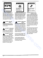
SAFETY INFORMATION
w
For Your Safetyl
These safety precautions should be followed at all times. Failure to follow these safety precautions could result
w
in serious injury to yourself and others.
yW
-M
AWARNING
AWARNING
AWARNING
�
~
J
Explosive Fuel
can cause fires and severe
burns.
..
can cause severe Injury.
Hot Parts
can cause severe burns.
Stay away while engine is in
operation.
operating or just after stopping.
Rotating Parts
Stop engine before filling
H
el
he
fuel tank.
.��II�m" )lJII,
WARNING: Rotating PartsI
Keep hands, feet, hair, and clothing
away from all moving parts to pre
vent Injury. Never operate the en
gine with covers, shrouds, or
guards removed.
WARNING: Hot Partsl
Engine components can get ex
tremely hot from operation. To pre
vent severe burns, do not touch
these areas while the engine is run
ning-or immediately after i t is
turned off. Never operate the engine
with heat shields or guards
removed.
se
or
WARNING: Explosive Fue/l
Gasoline is extremely flammable
and its vapors can explode If Ig
nited. Store gasoline only In ap
proved containers, in well
ventilated, unoccupied buildings,
away from sparks or flames. Do not
fill the fuel tank while the engine Is
hot or running, since spilled fuel
could ignite if it comes in contact
with hot parts or sparks from igni
tion. Do not start the engine near
spille d fuel. Never use gasoline as
a cleaning agent.
Do not touch engine while
om
-c
1.1
AWARNING
���
Accidental Starts
can cause severe injury
AWARNING
AWARNING
;;�i
�
Carbon Monoxide
Sulfuric Acid in batteries
can cause severe nausea,
fainting or death.
or death.
Disconnect and ground spark
Do not operate engine in
Charge only in well ventilation.
plug lead before servicing.
closed or confined area.
Keep sources of ignition away.
w
w
or death.
can cause severe injury
WARNING: Dangerous Acid,
WARNING: Lethal Exhaust Gases!
Before servicing the engine or
Engine exhaust gases contain poi
equipment, always disconnect the
sonous carbon monoxide. Carbon
Batteries contain sulfuric acid. To
spark plug lead to prevent the en
monoxide is odorless, colorless,
prevent acid burns, avoid contact
gine from starting accidentally.
and can cause death if inhaled.
with skin, eyes, and clothing. Bat
Ground the lead to prevent sparks
Avoid inhaling exhaust fumes, and
teries produce explosive hydrogen
that could cause fires. Make sure
never run the engine in a closed
gas while being charged. To pre
the equipment is in neutral.
building or confined area.
A
..
CAUTION: Electrical
Shockl
Never touch electrical wires or
components while the engine Is
running. T hey can be sources of
electrical shock.
Explosive Gasesl
vent a fire or explosion, charge bat
teries only in well-ventilated areas.
A
..
WARNING: Spring Under
yW
-M
w
WARNING: Accidental Starts!
Keep sparks, open flames, and
other sources of ignition away from
TensionI
Retractable starters contain a pow
erful, flat wire recoil spring that is
under tension. Do not remove the
center screw from the starter until
the battery at all times. Keep batter
ies out of the reach of children. Re
move all jewelry when serviCing
batteries.
e
he
the spring tension is released. Re
A
..
WARNING: Overspeed Is
Hazardousl
Do not tamper with the governor
setting. Overspeed is hazardous
A
..
WARNING: Flammable
Solvents!
leasing spring tension or improper
(-) ground cable, make sure all
starter disassembly, can cause the
switches are OFF. If ON, a spark
sudden and potentially dangerous
will occur at the ground cable ter
release of the spring.
minal which could cause an explo
Always wear safety goggles when
servicing retractable starters -full
face protection Is recommended.
are extremely flammable. Keep
sparks, flames, and other sources
To ensure personal safety and
of ignition away from the area. Fol
proper starter disassembly and
low the cleaner manufacturer's
reassembly, follow the procedures
warnings and instructions on its
In this section carefully.
proper and safe use. Never use
om
-c
gasoline as a cleaning agent.
sion if hydrogen gas or gasoline
vapors are present.
se
or
Carburetor cleaners and solvents
Before disconnecting the negative
lH
and could cause personal injury.
moving the center screw before re
1.2
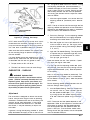
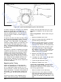
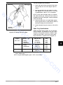
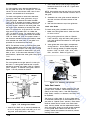
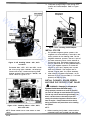
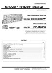
E N G I N E IDENTIFICATION N UMBERS
The engine identification numbers appear on a de
cal (or decals) affixed to the engine blower hous
ing . Refer to Figure 1 -1 . The significance of these
n u mbers is shown below :
When ordering parts , or in any communications
involving an engine, always give the model , speci
fication and serial n u mber of the engine .
A
A
KOHLER(�fJjl�TIlrJ[cq
w
00 !-iP
MODEL NO 0000
:;,:;OPERATION
,��w�,� ;OM�N��' ----- B
FOR
IN5TIIUCTIONS ANDMAINHNANC[
SAFElY
w
c
c
SERIAL NO
w
1IIIIIIIIIIII IIIIII III IIIImlllllllili
Identification
Decal
000000000
yW
-M
Figure 1 -1 . Location of E n g i n e
Identification Decal.
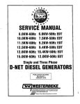
A. MODEL NO.
K
Eng i ne
1
PT
Q
R
S
T
ST
Si n gl e
A pproxi mat e
Cylinder
Dis placement
he
K- Se rl e s
32
A
C
G
P
(Cu. In.)
EP -
60 1 24B
II
1...-.- 1--'
f-----'
Variation of
B a s ic Engine
C. S E RIAL NO.
1 7 2 4 5 2
A Letter
A
B
C
D
E
1965
1966
1967
1968
1969
om
-c
se
or
K91
K161
K141
K181
K241
K301
K321
K341
H
26, 27, 31
28
29
30
46
47
60
71
-
-
Special 011 Pan
Clutch Model
Generator Application
Pump Model
Quiet Model
Reduction Gear
Electric Start
Retractable Start
Electric Start And
Retractable Start
Electric Plant
el
M2..d..!tl
�
E
-
Version Code
Engine Model Code
B. SPEC NO.
u
-
9 076 4 3 0
1 00 266 9 2
First Two Digits I If
Seven Digit Number
First Three Digits I If
Eight Digit Number
10-19
20-29
30-39
40-49
50-59
60-69
70-72
73-79
80-89
90-94
95-99
100-109
110-119
120-129
130-139
140-149
150-159
LJ
1969
1970
1971
1972
1973
1974
1975
1976
1977
1978
1979
L-..J
1980
1981
1982
1983
1984
1985
1 5 0 1 8 9 7 5 9 1
LJ
First Two Digits I If Ten
Digit Number
15
16
17
18
19
20
21
22
23
24
25
1985
1986
1987
1988
1989
1990
1991
1992
1993
1994
1995
Remaining digits are a factory cod e .
Figure 1 -2 . Engine Identification Decals.
1 .3
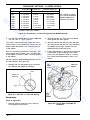
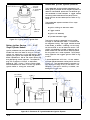
OIL RECOMMENDATIONS
NOTE:
Using the proper type and weight of oil in the engine
recommended could cause engine damage
crankcase a nd in the gear reduction unit is extreme
which is not covered by the engine warranty.
ly im portant, as is checking oil daily and changing oil
regularly.
Failu re to use the correct 011 or using
dirty oil causes premature engine wear and fail u r e .
Using other than Service Class SF or SG oil
or extending oil change intervals longer than
A logo or symbol on oil containers identifies the API
service c l ass and SAE viscosity g rade .
w
Oil Type
Use high-quality detergent oil of API (American Pe
w
troleum In stitute) Service Class SF or SG .
Select
the viscosity based on the air temperature at the
-M
w
time of operation as shown in the tab l e .
Rec•••ded
liE VisCOSity Grades
Check Oil Level
Check oil lever BEFORE E ACH USE.
yW
Straight 3D-weight oil is preferred.
SAE 1 DW-3D
(DoC) .
drain plug on the lower part of the cover .
Oil level
should be up to the bottom of the plug h o l e .
I f oil
level is low , remove the vented plug at the top of
the cove r , add oil until it reaches the bottom of the
drain plug hole, and replace drain plug and vented
e
he
and lDW-40 are not recommended above 32°F
Check gear reduction uniot oil level by removing the
Using these oils s ubstantially increases oil
consum ption and com bustion chamber deposits.
plug.
NOTE:
Do not operate the engine with the oil level
below the "L" mark o r over the "F" m a rk on
the dipstick.
Remove from block
Place on shoulder
Read level
Bayonet
o
-c
se
or
lH
Shoulder of flange
Figure 1 -3. Dipsticks And Oil Fill Tubes.
1.4
m
Push down on tube
Read level
Change O i l
Do not use gasoline left over frorn the previous sea
son, to minimize g u m deposits in your fuel system
and to insure easy starting .
For a new engine , change o i l aft�r the first 5
hours of operation . Change oil every 25 hours of
operation thereafter .
Do not add oil to the gasoline.
Do not overfill the fuel tank.
fuel to expan d .
w
w
For a n overhauled engine or o n e rebuilt with a new
shortblock or m iniblock, use straight 30-weight
Service Class SF or SG oil for the first 5 hours of
operation . C hange the oil after this initial run-in
period . Refill with Service Class SF or SG oil as
specified in the table. Change oil every 25 operat
ing hours thereafter.
Fuel Type
For best results , use only clean , fresh , unleaded
gasoline with a pump sticker octane rating of 87 or
highe r . In countries using the Research method , it
should be 90 octane minimu m .
FUEL R ECOMMENDATIONS
-M
w
£ WARNING:
Leave room for the
Unleaded gasoline i s recommended, a s it leaves
less combustion cham ber deposits . Leaded gaso
line may be used in areas where unleaded is not
available and exhaust em issions are not regulated .
Be aware however, that the cylinder head will re
quire more frequent service .
Explosive Fuel!
Gasoline may be present in the carburetor and fuel
system. Gasoline is extremely flammable and it can
explode if ignited. Keep sparks, open flames, and
other sources of ignition away from the engine. Dis
yW
connect and ground the spark plug lead to prevent
the possibility of sparks from the ignition system.
Gasohol (up to 1 0% ethyl alcoho l , 90% unleaded
gasoline by volume) is approved as a fuel for Kohler
engines . Other gasoline/alcohol blends are not ap
proved .
el
he
Gene ral Recommendations
Gasoline /Alcohol blends
Pu rchase gasoline in small quantities and store in
clean, approved containers . A container with a ca
pacity of 2 gallons or less with a pouring spout is
recom mended . Such a container is easier to handle
and helps elim inate spoilage during refueling .
Gasoline /Ether blends
or
H
Methyl Tertiary Butyl Ether (MTBE) and un leaded
gasoline blends (up to a maxi m u m of 1 5% MTBE by
vol ume) are approved as a fuel for Kohler engines .
Other gasoline/ether blends are not a pproved .
OIL REFILL QUANTITIES (U.S. STANDARD QUARTS)
1 Quart
K24 1 , K30 1 , K32 1 , K34 1
2 Quarts
K24 1 A , K30 1 A , K32 1 A , K34 1 A
-c
1 /2 Quart
K141 , K 1 6 1 , K1 81
se
K9 1
om
(After refilling, always check oil level -- DO NOT OVERFILL)
1 Quart*
* A-type oil pan capacity varies from 1 to 1 -3/4 quarts . On these add 1 quart of oil, check
leve l , then add oil as necessary to bring up to full level .
Figure 1 -4.
1 .5
HORSEPOWER (Maximum RPM)
En ine Model
4
Bore x Slroke
GENERAL
Displacement Cu. In.
Max. Op�
�ing RPM
New
Maximum
rl- i
Shall
0.0,
w
w
BALANCE
GEAR
End Play
Sleeve
CAMSHAFT
1.0.
Running
Clearance
CONNECTING
ROD
Installed
Play
Red To Crank.Pin '6
Rod To traItrLimit
Pi
Rod To Plslon
Pin
.
-M
w
New
·········Mallimum
.0051.020
.0051,010
,0051.010
.005/,010
.0051.010
.0051.010
.0051.010
.001/,0025
,001/.002
,001/.002
.001/,002
.0011.002
.0011.002
.0011.002
.003
.0025
.0025
,0025
.0025
.0025
.0025
.00071.0008
,0006/.0011
.0006/,0011
,00031.0008
,00031,0008
.00031,0008
.00031,0008
,62551.6258
.62551.6258
,8596/.8599
.87571,8760
,87571,8760
.87571.8760
I 1.181111.1814
1.181111.1814
1.574511.5749
1.5745/1.5749
1.574511.5749
1.574511.S749
1.1811
1.5745
1.5145
1.5145
1.5745
, 56301.5633
.98411.9844
.9841
M
1.1811
A
I
N
S
CRANKSHAFT
Maximum
.93601,9355
1.5001)11.4995
.9350
.0005
yW
.001
.004/.023
CYLINDER
BORE
IGNITION
Ne.
Maximum
.0021.023
2.375512.3745 2.9380/2,9370
m
i il
2.378
2,941
2,941
3.378
3.503
3.753
Max. Oul 01 Round
.003
.003
.003
.003
.003
.003
Max. Tall�r,
.003
,003
.003
.002
.002
.002
Max. Dul 01 Aatness
.003
.003
.003
.003
.003
.003
RCJ·8
RCJ·8
RCJ·8
RH·l0
RH·l0
RH·l0
.025
.025
.025
.035
.035
fl
l
S ark
lug
TY e
Gap
Type@
B attery
Magneto"
Gaseti-Ils
"I
Nominal Point Gap
PISTON
el
he
CYLlNDER
' HD .•
Inside
Dlameler
.025
.025
.025
.025
.025
.018
.018
.018
.018
.018
.020
.020
.020
.020
3.243213.2413
2.366
3.236
3.363
.0035/.006
.0071.010
.0071.010
.0071.017
.0101.020
.010{,020
or
H
.006
.006
3,370013,3693
New8ore@
Use; flore@)
Inlake
Exhaltst
&h_
VALVES
1.-
EJbaust
Valve
Elhallst
(j) Mru::imum limits combination of tD. and
0.0. measurements
� Ball boaring 1.377911,3784, Maximum Wear 1.3779
Q> 8all bearing 1.7716/1.7721. Maximum Wear 1.7716
•
.0045/.0062
.0050/.0067
.00301.0050
.010/.023
.0101.020
.0101.020
.0101.020
.032
.030
.030
.030
.006
.006
.006
.006
.56231,5625
.62471.6249
.62471.6249
.8591/.8593
.87521.8754
.8752/.8754
.87521.8754
.250
.3125
.3125
.3125
.3125
,3125
.3125
.0051.009
.00til.OOO
.00til.oOS
.b08I.010
.008/.010
.0111.015
.Om.019
.0171.019
.017/.019
.0171.019
.2035
.2718
.2710
.318
.1768
.2482
.2482
.318
.318
.2478
.3103
.3103
.3103
.3103
.2458
.3088
.3088
.3074
.3074
.318
45'
45'
45'
45'
45"
45'
45'
.005
.005
.005
.006
.006
.006
.006
.007
.007
.007
.008
.008
.000
.008
@ Pre Serles 111,3733/1.3738, Maximum Wear
@ BaH bearing .002/,023
® Champion spark plugs or equivalent
([) Measure just below oil ring groove and
at right angles to piston pin
1.3728
® 1800 RPM generator sets .005!.O07
® Measure 1f,z" above the bottom
of the piston skitt.
and center compression rings.
®I Top
Includes K141
Figure 1 -5 . E n g i n e Specificatio n s And Tolera nces.
1 .6
• .008l.010®
-----r--- -.0171.019
.0171.019
.0001.010
om
Seat
lilI...
3.367
.00341.0051
-c
Iq,te
2.931
se
.
Oulside Diameter
.030
.030
Ne.
,
.002
.003
3.36813.355
2,371/2,369
.027
Mal, iling Side Clearance
I
� � � XI%IXIX
HORSEPOWER (Max. RPM)
Engine Model
CONNECTING
RODS<D
K161
-
Posi-Iock®
w
18·22fl. Ibs.
w
w
4
g
1
�
�
0
2
a
\.-2
5
(QJ 2
I
0
(QJ
3
8
(QJ
01
9
K301, K321
25·30 II. lb•.
5
(lI
2
I (QJ
9
I
I
22-27 fl. lb•.
100·120 in. Ibo.
70·140 in. Ibo.
70·140 in. Ibo.
-
20·30 in.Ibo.
-
-
yW
-M
-
-
Cast Iron
250 in. Ibo.
Sheet Metal@)
50·60 II. Ibo.
Grade 5--250 in.Ibo.
-
200 in.Ibs.
MANIFOLD SCREW/NUT
-
-
-
CAMSHAFT NUT
-
-
-
37·45 in. Ibo.
he
in.
in.
In.
in.
In.
In.
'
165
200
350
30
50
m. lb.
m. lb.
m.
lb.
ft. lb.
It. lb.
60 ft. lb.
80
105
115
165
175
230
260
330
350
470
�
It. Ibo.
x
x
ft.
It.
It.
ft.
It.
ft.
ft.
lb.
lb.
lb.
lb.
lb.
lb.
lb.
ft. lb.
ft. lb.
ft. lb.
12 � In. Ibo.
1.3558 � N m
USED - Component that was in a running engine.
(lI
6
Aluminum Pans
1/4"
150 in. lb.
100 In. lb.
180 in. lb.
120 in. lb.
3/4"
CD Lubricate with engine oil
® DO NOT overtorque -loosen -and retorque the hex nuts on Posi-Lock connecting rods.
NEW - Component directly from stock.
2
3/8"
X·708·1@
It.lbo. x .1383�kgm
It. Ibo.
'���� "'9iJ
5
Tightening Torque
Cast Iron Pans
1/2"
in. Ibs x .083 = ft. Ibs.
Conversions
\
09
20 It. Ibo.
25 It. Ibo.
20·25 It. Ibo.
13 ft.lbo.
16 It. Ibo.
20·25 ft. Ibo.
Q)
®
G>
®
om
-c
se
40
40
115
140
250
270
35
40
55
75
80
105
125
165
180
230
245
325
lb.
In. lb.
m. lb.
m. Ib
m. Ib
In. lb.
In. Ib
It. lb.
ft. Ib
It lb.
It. lb.
It. lb.
It. lb.
It. lb.
ft. lb.
It. lb.
It. lb.
ft. lb.
ft. lb.
i\:.lI
or
lb.
lb.
lb.
lb.
lb.
lb.
In. lb.
in. lb.
in. lb.
It. lb.
ft. lb.
ft. lb.
ft. lb.
tt. lb.
It. lb.
ft. lb.
It. lb.
ft. lb.
It. lb.
10
25·30 ft. lb..
H
20
32
32
70
85
150
165
260
300
35
45
50
70
75
100
110
140
150
200
-c-
�
OIL DRAIN PLUGS
(Oil at Assembly)
el
Grade 8
0 7s{)� @
----ee
-
8·32
10·24
10·32
1/4·20
1/4·28
5/16·18
5/16·24
3/8·16
3/8·24
7/16·14
7/16·20
1/2·13
1/2-20
9/16·12
9/16·18
5/8·11
5/8-18
3/4·10
3/4·16
Grade 5*
Grade 2
Size
1
37·45 in.Ibo.
USE STANDARD TORQUE SETTINGS WHEN
SPECIFIC VALUES ARE NOT SPECIFIED.
Cast Iron or Steel
8
3511.lbo.
Grade 8-350 in.Ibo.
-
-
(QJ (QJ
2 (QJ
6
130·150 in.lbo.
NON METALLIC FUEL PUMP
MOUNTING SCREWS
•
i\:.lI
K241,
� 0
6
(7
(QJ
4
250 in. Ibo.
70·90 in.Ibo.
Aluminum
PAN
K161, K181
15·20 II. Ibl.
�(QJ
. 0
-
Plastic
OIL
3
0'
85-90 II.Ibo.®
Metal
GRASS
SCREEN
6,
�
40·50 II. lb•.
SCREW
GOVERNOR BUSHING
�)
18·22 II. Ibs.
6
K341
Used 200 In.Ibs.
18·22 II. Ibs.
�
NUT
FLYWHEEL
RETAINING
K321
K301
New 260 In.Ibo.
285 In.Ibs.
K91
200In.lb'.
HEAD<D
K241
200 In.Ibs.
P
CYLINDER
1
New 140 In. lb•.
Used 100 In. lb•.
140In.Ibs.
Capscrew@
SPARK PLUGS
-
Overtorque 20%, loosen below torque value and retorque to final torque value
Torque twice with minimum of one minute interval
3/8�16 thread with hex head nut and fibre gasket
Poor to Ser. #23209832
45-55 �. Ibo.
Includes K141
Fig u re 1 -6 . Torque Values & Sequences For Fasteners.
1 .7
SECTION 2
SPECIAL TOOLS
w
w
SPECI A L S ERVICE TOO L KIT N O . 321 1 -A
-M
w
These q uality tools a re designed to help you per
form specific d isassembly, repair and reassembly
procedure s . By using tools designed for the job,
you can service engines easier, faster and safer!
In addition , you'll increase you r service capabilities
and customer satisfaction by decreasing engine
down time.
-c
se
or
H
el
he
yW
The Special Service Tool Kit No. 3 2 1 1 -A can be
ordered complete as shown in Figu re 2-1 or the
tools can be ordered individually. Contact your
Kohler Engine Distributor for price and availability .
Figure 2 - 1 . S pecial S e rvice Tool Kit
om
2.1
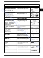
VALVE SERVICE TOOLS
TOOL NO. & N AME
VALVE SEAT PULLERS
Re moval of valve seats, Use
11726
11913
adapter,
w
FORC I N G SCREW
w
w
ADAPTER
&
©
yW
-M
~
Used to install intake and exhaust
seats. Use with
4747
h an d l e
Provi des pul l i n g force for valve seat
a n d guide removal. Use
Wei g h t
4747
han dle.
S l i d e Bolt
Stud
Stud
3 112"
2 1/2"
sli d e hammer
Adapter
Nut
3224 VALVE GUIDE INSTALLER KIT
Gag e
l��I1ll»
11770
&
11771
11763
driver with
depth gages
To ream valve g uides
CW
or
REAMERS (Valve G uide)
�
( lilHll!!
Used to i n stall valve g uides to
proper depth. Use
Gage
,:::c·····
�
....�
:x:J�
om
-c
se
11843 5/16"
11844 114"
�
�,"'"
(til
)1
I
�
H
Driver
3222
el
Nut
Driver
Used to pull valve guides with
he
3268 VALVE GUIDE REMOVAL KIT
{gp
D:
11913
Used to con n ect valve seat pullers
3222 SLIDE HAMMER
12325
11763
11770
11771
11726
�
to sli d e h a m m er
VALVE SEAT I NSTALLER
11838
12100
11800
0917
12008
11918
11915
slide hammer &
Used with valve seat
pullers
11918
11799
12244
3222
forc i n g screw
11915
11811
11812
ILLUSTRATION
APPLICATION
SEAL AND BEARING INSTALLERS
3223 SEAL I NSTALLER KIT
11782 Seal Installer
11783 Seal Installer
11784 Seal Installer
11785 Seal Installer
11786 Seal Installer
11787 Seal Installer
11790 Seal Installer
11791 Seal Installer
11792 Seal Installer
11793 Seal Installer
11795 Handle
2.2
Used to install seals without
damage an d to proper depth. Use
11795
h an d l e with installers
\\
JjJ
V
-
SEAL AND BEARING INSTALLERS
TOOL NO. & NAME
3242 SEAL PROTECTOR SLEEVE KIT
.75"
1.25
1.50
w
w
12020
12022
12127
12021
12126
12128
1.00
1.12
1.44
3241 BEARI N G I N STALLI N G KIT
-M
w
12014 I n s. (Cra n k Bush i n g )
12015 I ns. (Cam Bush i n g)
12016, 12017, 12018 & 12109
ILLUSTRATION
APPLICATION
Used on cran kshaft when i n stalli n g
Used to i n stall & remove e n g i n e
@~
bear i n g s a n d bush i n gs
Brg. I n sta l l ers
3226 FLYWHEEL PULLER KIT
Puller wlforc i n g screw
Bolt -
1/4" wlwasher (3)
Bolt - 10-24 wlwasher (2)
Bolt - 3/8" wlwasher (2)
Wre n c h
Wre n c h
1/2"
9/16"
n
Used to re move & i nsta l l cyli n d er
barrel retai n i n g n u ts
Used t o set o i l p u m p drive gear
�-
Han d l e
TOOL BOARD AND HOOK SET
�
Used to scrape mach i n e d surfaces
wi thout damage
Used w i th bear i n g i nstal lers, sli d e
hamm er, a n d valve seat i nstallers
Used to store a n d i d en t i fy too l s
[
:=J
om
HANDLE
position when asse m b l i n g e n g i n e
-c
SCRAPER
11762
Used t o h o l d balance g ears i n t i med
0)
se
T i m i n g Gage
)
��=
Used to ho l d f l ywheel for n ut
bac k l ash on twin cyl i n d er e n g i n e
TIMI N G GAGE
��
r
J
or
H
FEELER GAGE
11767
12033
«(( (C
removal
OFFSET WRENCH
4747
bear i n g plates from e n g i n e
el
he
FLYWHEEL STRAP WRENCH
10355
Used to remove f l ywheels a n d
Storage Bag
10357
11797
4923
OTHER APPLICATIONS
yW
12485
5108
12505
12504
12506
)
a
seals to prevent damage
�
SEE FRONT PAGE
2.3
KIT NO. 3211 -A
TOOL USAGE CHART
PART NO & NAME
,...
Ol
�
VALVE TOOLS
w
11726 Valve Seat Puller
�
•
•
11913 Valve Seat Puller
11915 Forcing Screw
11811 Valve Seat Installer
11812 Valve Seat Installer
•
3222 Slide Hammer
3268 Valve Guide Removal Kit
yW
-M
11763 Valve Guide Driver (depth)
11770 Valve Guide Depth Gage
11771 Valve Guide Depth Gage
11843 Valve Guide Reamer 5/16"
11844 Valve Guide Reamer 1/4"
�
"
�
�
�
•
•
•
•
•
•
•
•
•
•
•
•
•
•
•
•
•
MODEL ( K" SERIES)
.
,... ,... ,... ,... ....
,... Ol
,...
("II
'<t
0
'<t
M
M
� CO?
..:. ..:.
•
•
•
•
•
12325 Valve Guide Driver
,...
co
,...
•
•
w
w
11918 Adapter
1
,...
co
,...
•
•
•
•
•
•
•
•
•
•
•
•
•
•
•
•
•
•
•
("II
co
LO
�
�
�
U?
�
•
•
•
•
•
•
•
•
•
•
•
•
•
•
•
•
•
•
•
•
•
•
•
•
•
•
•
•
•
("II
M
•
•
•
•
•
(1)
•
•
•
•
�
•
•
•
•
•
K T19 engines p r i or to Seri es II (Spec No. 49 1 99 and l ower).
BEARING AND SEAL INSTALLERS
12014 Installer - Crank Bushing
12015 Installer - Cam Bushing
•
he
12016 Installer - Bearing
12017 Installer - Bearing
12018 Installer - Bearing
(PTa)
•
12019 Installer - Bearing
11782 Installer - Seal
•
(PTa)
11784 Installer - Seal (PTa)
(PTa)
11787 Installer - Seal
(PTa)
•
•
11786 Installer - Seal (Flywheel)
11790 Installer - Seal (Flywheel)
•
•
11791 Installer - Seal (PTa)
11792 Installer - Seal (Flywheel)
12020 Seal Sleeve
12021 Seal Sleeve
•
•
•
•
•
•
•
•
•
•
•
•
•
•
•
•
•
•
•
•
• • •
• •
USE AS REQUIRED
•
•
•
om
-c
se
USE AS REQUIRED
12022 Seal Sleeve
USE AS REQUIRED
12127 Seal Sleeve
12128 Seal Sleeve
USE AS REQUIRED
USE AS REQUIRED
USE AS REQUIRED
12126 Seal Sleeve
MISCELLANEOUS TOOLS
10357 Flywheel Strap Wrench 1/2"
11797 Offset Wrench 1j,"
•
•
•
•
•
•
4923 Offset Wrench 9/16"
11767 Feeler Gauge-Crankloll Pump)
10355 Timing Tool (Balance Gear)
11762 Scraper
4747 Drive Handle
•
•
•
•
•
•
•
or
11793 Installer - Seal (Flywheel)
11795 Handle - Installer Seal
3226 Flywheel Puller Kit
•
•
•
•
•
•
•
•
•
•
•
•
•
•
•
•
NOTE: K1 4 1 requ ires same tools as K1 6 1 .
2.4
•
H
11785 Installer - Seal
•
el
11783 Installer - Seal (Flywheel)
•
•
•
•
•
•
•
•
•
•
•
•
•
•
•
•
•
•
•
•
•
•
•
•
•
•
•
•
•
•
•
•
•
•
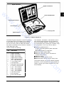
D igital Tachometer
Digital Thermometer
w
w
Slack Tube Manometer
Digital E n gine Analyzer
-M
w
Thermocouples
Carrying Case
yW
Digital Voltmeter
Figure 2 - 2 . Eng i n e Analysis Kit
el
he
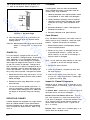
The Kohler E ngin e Analysis Kit contains a selection
of i n stru me n ts which will enable you to measure
critical items that relate to engine performance.
You will find many uses for these instruments from basic crankcase vacuu m c hecks to sophisti
cated app l ication tests.
The kit includes the following:
2
1
1
1
1
1
1
1
3
The E ngine Analyzer Kit can be ordered complete
as shown . or the i nstrum ents can be ordered indi
vidually. Contact your Kohler D i stributor for price
and availability.
om
Digital Voltmeter
Digital Tac hometer
D i gital Thermometer
Digital Engine A nalyzer
Slack Tube Manometer
8 Ft. Lead With Plug
1 4 m m Spark Plug
Thermocouple
Head Bolt Thermocouple
O i l Sump Thermocouple
1 /4 " x 1 /8 " Bushing
318 " x 1 /8 " Bushing
1 /2 " x '/8 " Bushing
3/4" x 1 /8 " Bushing
Tube With Fittings
Carryi ng Case
Plain Thermocou ple
-c
1
1
1
1
1
1
3
se
Descript i o n
• M easure tem peratures of • spark plug base gasket/cylinder head bolt.
• oil s u m p .
• a i r into flywheel a n d carburetor.
• Measure engine speed (RPM ) .
• Measure crankcase vac u u m and exhaust
system back pressure .
• Measure voltage.
• Measure chargin g system c u rrent.
• Measure e lectric starter current (Amp) d raw .
or
H
Qly.
The voltmeter. tachometer. thermometer and en
gine analyzer feature state of the art e lectronic
circuitry and digital readouts . Guidelines for using
the i nstruments and for testing are included. Using
the instruments in the kit you will be able to:
2.5
SECTION
3
PERIODIC MAINTENANCE
w
w
RE QUIRED MAINTENANCE
These required maintenance procedures should be performed at the frequency stated in the table :
Frequency
w
Required Maintenance
.
.
.
.
.
.
.
.
.
.
.
.
.
.
.
.
.
.
.
.
.
.
.
.
.
.
.
.
.
.
yW
-M
Check Oil Level . . . . . . . .
Clean Grass Screen . . . . .
Clean/Replace Fuel Filter .
Clean Foam Precleaner . .
Change Oil . . . . . . . . . . . . .
Check Optional Reduction
Gear Unit . . . . . . . . . . . . . .
Clean Cooling Fins and
External Surfaces . . . . . . .
Clean Paper Air
Cleaner Element . . . . . . . .
Check Spark Plug . . . . . . .
Check Valve-To-Tappet
Clearance . . . . . . . . . .
Clean Cylinder Head and
Combustion Chamber* . . .
Service Starter
Motor Drive . . . . . . . . . . . .
.
.
.
.
.
.
.
.
.
.
.
.
.
.
.
.
.
.
.
.
.
.
.
.
.
.
.
.
.
.
.
.
.
.
.
.
.
.
.
.
.
.
.
.
.
.
.
.
.
.
.
.
.
.
.
.
.
.
.
.
.
.
.
.
.
.
.
.
.
.
.
.
.
.
.
.
.
.
.
.
.
.
.
.
.
.
.
.
.
.
.
.
.
.
.
.
.
.
.
.
.
.
.
.
.
.
.
.
.
.
.
.
.
.
.
.
.
.
.
.
.
.
.
.
.
.
.
.
.
.
.
.
.
.
.
.
.
. .. .
. . . .
. . . .
. . . .
. . . .
. . . . . . . . . Daily
. . . . . . . . . Daily *
. . . As Required
. . . . 2 5 Hours *
. . . . . 2 5 Hours
.
. . . . . . . . . . . . . . . . . . . . . . . . . . . . . . . . . . . . . . . . . . . 50 Hours
. . . . . . . . . . . . . . . . . . . . . . . . . . . . . . . . . . . . . . . . . . . 50 Hours *
. . . . . . . . . . . . . . . . . . . . . . . . . . . . . . . . . . . . . . . . . . 1 00 Hours *
. . . . . . . . . . . . . . . . . . . . . . . . . . . . . . . . . . . . . . . . . . 1 00 Hours
he
.
.
.
.
.
.
. . . . . . . . . . . . . . . . . . . . . . . . . . . . . . . . . . . . . . . . . . 500 Hours
el
. . . . . . . . . . . . . . . . . . . . . . . . . . . . . . . . . . . . .
. . . . . . . . . . . . . . . . . . . . . . . . . . . . . . .
.
. . . .
.
500 HoursH
Annually or 500 Hours
* * 250 Hours when leaded gasol ine is used .
Before seNicing the engine or equipment, always
remove the spark plug to prevent the engine from
starting accidentally. Ground the lead to prevent
sparks that could cause fires.
CHECK OI L LEVE L
The importance of checking and maintaining the
pro per oil level in cran kcase cannot be overem
phasized . Check oil BEFORE EACH USE as follows :
om
-c
se
� WARNING: Accidental Starts!
or
H
* Perform these maintenance procedures more frequently when engine is operated u nder
extremely dusty and dirty conditions .
1 . Make sure the engine is stopped , level , and is
cool so the oil has had time to drain into the
sump.
2 . Clean the area around oil fill cap/dipstick be
fore removing to keep dirt , grass clippings ,
etc . , out of the engine .
3. Remove oil fill cap/dipstick ; wipe oil off . Rein
sert dipstick and push it all the way down into
tube. Remove dipstick and check the level .
4 . On engines with threaded type plug dipstick,
shoulder plug on top of hole to observe level .
3.1
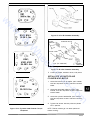
The oil level should be up to. but not over. the
" F " mark on the dipstick. Refer to Figure 3-1 .
Precleaner
If so equipped . wash and reoil the precleaner
every 25 operating hours (more often under ex
tremely dusty. dirty conditions) .
1 . Remove precleaner from paper element. Wash
the precleaner in warm water with detergent.
w
w
f
Operating
Range
2 . Rinse precleaner thoroughly until all traces of
detergent are eliminated . Squeeze out excess
water (do not wring ) . Allow precleaner to air
dry.
�
3 . Saturate precleaner in clean . fresh engine oil .
Squeeze out excess oil .
-M
w
Figure 3-1 . Oil Level Ran g e .
Reinstall precleaner over paper element.
Paper Element
5. Add the proper type of oil if the Jevel is low .
Always check the level with dipstick before
adding more oil .
Every 1 00 hours of operation (more often under ex
tremely dusty or dirty conditions) , check the paper
element . Replace the element as necessary.
1. Remove the precleaner (if so equipped) , element
cover, and paper element.
2.
Replace a d irty, bent , or damaged element with
a genuine Koh ler element . Handle new ele
ments carefully; do not use of the sealing sur
faces are bent or damaged .
el
he
yW
CAUTION : Never operate the engine with the oil level
below " L " mark or over .. F " mark on dip
stick.
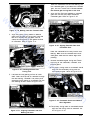
CHANGE OIL
4.
1 . Remove the oil drain plug and dipstic k . Tilt the
engine slightly towards the drain hole to obtain
better drainag e .
Fill with new oil of the proper type to the " F "
mark o n t he dipstick. Always check the level
on dipstick before adding more oil. Make sure
the engine is level when filling and checking
oil .
5.
I nstall the air cleaner cover and wing nut. Tight
en wing nut . Make sure element is sealed tig ht
ly against air cleaner base .
Inspect Ai r Cleane r Components
Whenever the air cleaner cover i s removed . or serv
icing the element or precleaner, check the followi ng
components:
Air Cleaner B a s e
Make sure it is secured tightly to
carburetor and is not bent or damaged .
-
om
3.
4. Install the precleaner (cleaned and oiled) over
the paper element .
-c
Reinstall t h e drain plug . Make sure i t i s tight
ened securely.
3. Reinstall the paper element .
se
2.
NOTE: Do not wash the paper element or use com
pressed air as this will damage element .
or
H
For a new engine , change oil after the first 5
hours of operation . Change oil every 25 operating
hours thereafter. For an overhauled engine or
those rebuilt with a new shortblock or miniblock ,
use straight 3D-weight Service Class SF or SG oil
for the first 5 hours of operation . Change the oil
after this initial run-in period . Change oil every 25
hours thereafter. Drain oil while the engine is still
warm from operation . The oil will flow freely and
carry away more impurities . Change oil as follows :
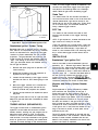
Element Cover a n d E le m en t Cover Nut - On K 1 81
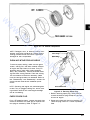
S E RVICE AIR CLEANER
K-Series engines are equipped with a h igh-density
paper air cleaner element. Some specifications
are also equipped with an oiled foam precleaner
which surrounds the paper element . Refer to Fig
ure 3-2 .
3.2
New Look �ngi nes only, make sure element cover
is not bent or damaged. Check that element cover
nut is secured tightly to seal element between air
cleaner base and element cover. Tighten nut to
50 in . lb. torq u e .
Make sure it i s sealed tightly in air
cleaner base and breather cover.
Breather Tub e
-
w
w
-M
w
·
""-- PRECLEANER
(OPTION)
yW
Figure 3-2 . Air Cleaner Components.
Wire Gauge ---�v
el
he
NOTE : Damaged , worn , or loose a ir cleaner com
ponents could allow unfiltered air i nto the engine
causing premature wear and failure . Replace a l l
damaged o r worn components .
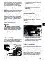
CLEAN A I R I NTAKE /COOLING AREAS
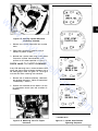
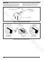
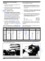
Figure 3-3. Servicing Spark P l u g .
1 . Before removing spark plug , clean the area
around the base of plug to keep dirt and de
bris out of engine.
om
Every 1 00 operating hours , remove the spark plug ,
check its condition , and reset gap or replace with
new plug as necessary. Refer to Figure 3-3.
Ground Electrode
-c
CHECK S PARK PLUG
se
NOTE : O perating the engine with a blocked g rass
screen , dirty or p lugged cooling fins, and/or cool
ing shrouds removed will cause engine damage
due to overheating .
or
H
To ensure proper cooling , make sure the grass
screen , cooling fins, and other external surfaces
of engine are kept clean at all times . Every 50
operating hours ( more often under extremely
dusty, d irty conditions) , remove the blower hous
ing and other cooling shrouds . Clean the cooling
fins and external surfaces as necessary. Make
sure the cooling shrouds are reinstalled . Refer to
the " Disassembly " and " Reassembly" sections for
cooling shroud removal and installation proce
dures .
2. Remove the plug and check its condition . Re
place the plug if worn or if reuse is question
able .
3.3
NOTE : Do not clean the spark plug in a machine
using abrasive g rit . Some grit could remain in
spark plug and enter the engine causing extensive
wear and damage .
3. Check gap using a wire feeler gauge . Adjust
gap by carefully bending the ground electrode.
w
4 . Reinstall spark plug into cylinder head . Torque
plug to 1 8/ 2 2 ft. l b .
w
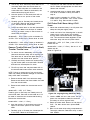
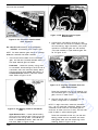
SERVICE OP ,.IONA L REDUC ,.ION G EAR
UNIT
w
On engines equipped with a reduction gear unit ,
check the oil level in unit every 50 operating
hours. Refer to Figure 3-4.
F ig u re 3-5. I n - l i n e Fuel Filter.
yW
-M
�
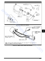
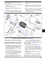
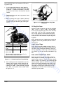
SERVICE STARTER MOTOR DRIVE
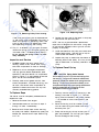
Vented Oil
Fill Plug
Every 500 operating hours or annually (whichever
occurs first ) , clean and lubricate the drive splines
of the Bendix-drive electric starter motor.
o
1. Remove starter from crankcase . (Refer to ap
propriate .. Disassembly " section . )
he
2 . Remove d ust cover , stop n ut , stop g ear
spacer, spring, d ust cover spacer, and d rive
pinion .
el
3. Clean the drive shaft splines with solvent . Dry
solvent thoroughly.
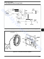
2 . To add oil , remove the vented fill plug at the
top of the unit . Use the same type of oil as
used in the engine crankcase .
3. Reinstall and tighten the plugs securely.
CHECK FUE L FI LTER
Some engines are equipped with an in-line fuel
filter. Visually inspect the filter periodically. Re
place when dirty with a genuine Kohler filter. Refer
to Figure 3-5.
3.4
NOTE : Kohler starter drive lubricant (Part N o . 52
357 01) must be used on all Kohler electric starter
d rives . The use of other lubricants can cause the
d rive to stick o r bind .
om
-c
se
1. Remove the plug on the lower part of gear unit
cove r . With engine leve l , the oil should be up
to the bottom of t he plug hole .
or
Figure 3-4. Reduction Gear Unit.
H
Drain Plug
(Oil Level Check)
4. Apply a small amount of Kohler electric starter
drive lubricant ( Part N o . 52 357 01) to splines.
5 . Apply a small amount of Loctite@ No. 271 to
stop nut thread s . Assemble drive parts in re
verse order of removal . Torque stop nut to
160 i n . l b .
6 . Reinstall starter t o crankcase . (Refer t o appro
priate " Reassembly " section . )
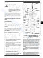
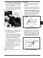
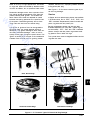
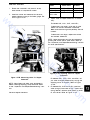
C LEAN CY LINDER H EAD AND COMBU S
TION CHAMBER
Every 500 operating hours (250 hours when leaded
g asoline is used) , remove cylinder head and clean
combustion chamber . Refer to Figure 3-6 .
w
w
w
g1
K161, K181 1\1
15-20 ft. Ibs.
yW
-M
Fig ure 3-6. Cleaning Cylinder Head And
Combustion Chamber.
1. Remove the cylinder head baffle and cyl1nder
head .
�2
2 . Clean away combustion deposits using a
wooden or plastic scraper.
3. Reinstall the cylinder head using a new gasket .
Torque the cylinder head fasteners in se
q uence to the values specified in Figure 3-7 .
({)) 8
he
7
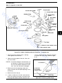
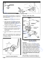
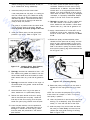
CHECK VALV E -TO -TAPPET CLEARANCE
CO)
Every 500 operating hours, remove breather/valve
cover and check valve-to-tappet clearance with a
flat feeler gauge . Refer to Figure 3-8 . The engine
must be cold when checking t his clearance .
(Q)
el
©
K241,
K301, K321
25-30 ft. Ibs.
9
({))
({J) 6
({))s
om
-c
se
({))
3
*
Figure 3-8. Measuring Valve-To-Tappet
4
or
2 . Position the crankshaft so the piston is at top
of com pression stroke (cam has no effect on
tappets) .
3
({)) 1
H
1. Remove the air cleaner assembly, carburetor,
and breather assembly . ( Refer to appropriate
.. Disassembly " section . )
Clearance.
II
K341
25-30 ft. Ibs.
yS
({)) 2
I ncludes K 1 4 1
Figure 3 - 7 . Cyl inder Head Fastener
Tightening Sequence.
3 . Measure valve-to-tappet clearance with a flat
feeler gauge .
On M odel K9 1 , K 1 4 1 , K 1 6 1 , K 1 8 1 -If the
clea rance is too small, remove the valves and
grind the valve stems until the correct clear
ance is obtained . Make sure valve stems are
ground perfectly flat and smooth .
Intake Valve
Exhaust Valve
K9 1
. 005 " / . 009 "
.01 1 "/.01 5 "
w
w
Model
K1 6 1 , K1 8 1
. 006 " 1 . 008 "
.01 7 " / .01 9 "
K24 1 , K301
K32 1 , K34 1
. 008 " / . 0 1 0 "
.01 7" /.01 9 "
STORAGE
If the engine will be out of service for approxi
mately two months or more , use the following
storage procedure .
1 . Change the oil when engine i s still warm from
operation . Refer to .. Change Oil . "
-M
w
2 . Change the oil in reduction gear unit , if so
equipped . Refill with the same oil as used in
engine crankcase for season of operation. Re
fer to " Service Optional Reduction Gear Unit . "
Run engine for a few minutes to distribute
clean oil throughout engine.
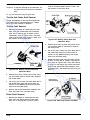
Figure 3-9 . Valve Clearances
If clearance is too large, replace the valves and
recheck clearance .
yW
NOTE : Large clearances can also be reduced by
grinding the valves and lor valve seats. Refer to
the " Inspection And Repair/Reconditioning " section
for valve specifications .
On Models K 2 4 1 , K301 , K 3 2 1 , K341 - Adjust the
clearance by turning the adjusting screw on tap
pets . Refer to Figure 3-9 .
3. Drain the fuel tank and fuel system (or run
engine until fuel tank and fuel system are
empty) .
4.
Remove the spark plug . Add one tablespoon
of engine oil into the spark plug hole . I nstall
plug , by do not connect plug lead . Crank the
engine two or three revolutions.
el
he
5 . Remove the spark plug. Cover the spark plug
hole with thumb and turn engine over until the
piston is at the top of its stroke (pressure
against thumb is greatest) . Reinstall plug , but
do not connect plug lead .
6 . Clean the exterior surfaces of engine. Spread
a light film of oil over any exposed metal sur
faces of engine to prevent rust .
Figure 3 - 1 0 . Adjusting Valve-To-Tappet
Clearance - Models K 2 4 1
om
-c
se
Through K34 1 .
or
H
7 . Store the engine in a clean , dry place .
3.6
SECTION
4
TROUBLESHOOTING
w
w
TROUBLESHOOTING G UIDE
-M
w
When trouble occurs , be sure to check the simple
causes which , at first , may seem too obvious to
be considered . For exa mple , a starting problem
could be caused by an empty fuel tank.
Some common causes of engine troubles are
listed below. Use this as a guide to locate trouble
causing factors .
Engine Cranks But Will Not Start
Empty fuel tan k .
2.
Fuel shutoff valve closed .
yW
1.
2.
Battery is discharged .
3.
Safety interlock switch is .. engaged " .
4.
Loose or faulty wires o r connections .
5.
Faulty keyswitch o r ignition switch .
6.
Faulty electric starter/starter solenoid .
7.
Retractable starter not engaging i n drive cup.
8.
Seized internal engine components .
Engine Runs But Misses
1.
Dirt or water in fuel system .
2.
Spark plug lead loose .
3.
Loose wires or connections intermittently shorting ignition to ground .
Clogged fuel line.
4.
Carburetor improperly adjusted .
Spark plug lead disconnected .
5.
Engine overheating .
5.
Keyswitch o r kill switch i n " off " position .
6.
Incorrect valve-to-tappet clearance .
6.
Faulty spark plug.
Engine Will Not Idle
7.
Faulty ignition .
8.
Dirt o r water i n fuel system .
el
he
3.
4.
E n g i n e Starts But Does Not Keep Runn i n g
1.
Restricted fuel tank vent .
Dirt o r water in fuel system .
Faulty choke or throttle controls/cables.
4.
Loose wires or connections shorting ignition to
ground .
5.
Carburetor improperly adjusted .
6.
Fau lty cylinder head g asket .
7.
Fau lty fuel pump.
Dirt o r water in fuel system .
3.
Idle fuel adjusting screw im properly set .
4.
Fuel tank vent restricted .
5.
Faulty spark plu g .
6.
Incorrect valve-to-tappet clearance.
7.
Low compression .
Engine Overheats
1.
Grass screen , cooling fins or shrouding
clogged .
2.
Excessive engine load .
3.
4.
Low crankcase oil level .
5.
Carburetor improperly adjusted .
High crankcase oil level .
Loose wires o r connections .
Engine Knocks
3.
Dirt or water in fuel system .
1.
Low crankcase oil level .
4.
Clogged or restricted fuel lines.
2.
Excessive engine loa d .
5.
Faulty choke or throttle controls/cables .
Engine Loses Power
6.
Faulty spark plug .
7.
Carburetor improperly adjusted .
8.
Incorrect valve-to-tappet clearance .
9.
Low compression .
1 0 . Faulty ACR mechanis m .
Engine Will Not Crank
1.
Hydrostatic transmission is not in neutral/PTO
drive is engaged .
1.
Low crankcase oil level .
om
-c
2.
Hydrostatic transmission not in neutral/PTO
drive is engaged .
Idle speed adjusting screw improperly set .
se
Engine Starts Hard
1.
2.
or
H
2.
3.
1.
II
2.
High crankcase oil level .
3.
Restricted air cleaner element.
4.
Dirt or water i n fuel system .
5.
Excessive engine load .
Engine overheatin g .
6.
7.
Faulty spark plug .
8.
Carburetor improperly adjusted .
4. 1
9.
C LEANING THE E N G I N E
Low compressio n .
E n g i n e Uses Excessive Amount o f O i l
1.
I ncorrect oil viscosity or type .
2.
Clogged o r improperly assembled breather
system .
3.
Worn o r broken piston rings .
4.
Worn cylinder bore .
w
w
5.
Worn valve stems and/or guides.
EXTERNAL E N G I N E INSPECTION
o
-M
w
o
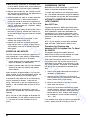
Before cleaning or disassembling the engine,
check its external appearance and condition .
This inspection can g ive clues to what might
be fou nd inside the engine (and the cause)
once it is disassembled .
Check for build u p of dirt and debris on the
crankcase, cooling fins, grass screen and
other external surfaces . Dirt or debris in these
areas are causes of overheating.
yW
Check for obvious fuel and oil leaks and dam
aged components . Excessive oil leakage can
i ndicate a clogged or i mproperly assembled
breather, worn or damaged seals and gaskets
or loose or improperly torqued fasteners .
D
Check the air cleaner cover, element cover
and air cleaner base for damage or indications
of improper fit or seal .
o
Check the air cleaner element . Look for holes,
tears, cracked or damaged sealing surfaces or
other damage that could allow dirt to enter the
engin e . Also note if the element is clogged or
restricted. These conditions could indicate that
the air cleaner has been underserviced .
o
Check the carburetor throat for dirt . Dirt in the
throat is further indication that the air cleaner
is not functioning properly.
o
Check the oil level . Note if the oil level is
within the operating range on the dipstick, or if
it is low or overfilled .
o
Check the condition of the oil . Drain the oil
into a container - it should flow freely. Check
for metal chips and other foreign particles.
BASIC E N G I N E TESTS
Fuel System Test
To determine if fuel is getting to the carburetor,
disconnect the fuel line at inlet to carburetor - if
fuel does not flow out of line, check system back
to tank for clogged lines, wrong (unvented) filler
cap, blocked filter screen, faulty fuel pump, etc . If
fuel is getting as far as the carburetor, remove
the spark plug , crank engine and check for fuel
inside combustion chamber. If n o fuel is present
here , check for faulty carburetor.
To determine if the ignition system is good, re
move the spark plug and place plug with side
electrode against cylinder head then crank engine
at sufficient speed to produce a good spark. If a
sharp, snappy spark is noted, this eliminates the
ignition system components as the cause, al
though the ignition timing could be off .
If no spark or a weak spark is produced , check
the ignition system further. If points are pitted,
don't attempt to service them - replace points in
bad shap e . Dirty points may be cleaned . A bad
condenser will cause premature failure of pOints .
Check the breaker p ush rod for evidence of bind
ing or sticking - replace as needed . Condenser
can be tested on commercial tester per tester
manufacturer's instructions. Check ignition coil on
coil tester for continuity.
om
Crankcase Vacuum
-c
se
Sludge is a natural by-product of combustion ; a
small accumu.lation is normal. Excessive sludge
formation could indicate that the oil has not been
changed as recommended, an incorrect type or
weight of oil has been used , over-rich carburetor
setti ngs or weak ignition, to name a few .
Ignition System Test
or
H
NOTE : It is good practice to drain oil at a location
away from the workbenc h . Be sure to allow ample
time for complete drainage .
4.2
There are many commercially available cleaners
that q uickly remove grease, oil and grime from
engine parts . When such a cleaner is used, follow
the manufacturer's instructions carefully. Make
sure all traces of the cleaner are removed before
the engine is reassembled and placed in opera
tio n . Even small a mounts of these cleaners quickly
break down the lubricating properties of engine oil .
el
he
D
After inspecting t h e external condition o f t h e e n
gine, clean it thoroughly before disassembling .
Also clean individual components as the engine is
disassembled . Only clean parts can be accurately
i nspected and gauged for wear or damag e .
A partial vacuum should exist in the crankcase
when the engine is operating at normal tempera
tures . Pressure in the crankcase (usually caused
by a clog ged or i mproperly assembled breather)
can cause oil to be forced out at oil seals, gas
kets or other available spots.
Crankcase vacuum is best measu red with a slack
tube manometer . The manometer included in the
side . If there is no vacuum {level in engine
side is the same as in open side) or a positive
pressure (level in open side is higher t han in
engine side) check for the conditions in the
following table .
Kohler Engine Analysis Kit is recommended . Refer
to the " Special Tools " section for more informa
tion .
Crankcase Vacu u m Test
4.
To test crankcase vacuum with t he manometer:
1.
Insert t he stopper hose into the oil fill hole.
Leave the other vent of the manometer open
to the atmosphere . Make sure the shutoff
clamp is close d .
Close the shutoff clamp before shutting off the
engine .
w
w
Compression Test
Start t h e engine a n d r u n a t h i g h speed (3200
to 3600 RPM) .
3.
Open the clamp and note the water level in
the tube . The level in the engine side should
be 5 to 1 0 inches above the level in the open
To check the condition of the combustion chamber
and related mechanisms, physical inspection and a
crankcase vacuum test are reco mmended .
-M
w
2.
Because t hese engines a re equipped with an auto
matic compression release mechanism (ACR) . it is
difficult to obtain an accurate compression read
ing .
NO CRANKCASE VAC U UM/PRESSURE I N CRAN KCASE
Solution
Possible Cause
yW
1 . Di sasse m bl e breather, clean parts thoro u g h ly,
reassem bl e . and rec heck press u re.
2. Seals an d/or gaskets lea k i n g . Loose or
i m pro perly torq u ed fasteners.
2. Rep lace all worn or damaged seals and gaskets.
M ake s u re fasteners a re t i g h tened sec u rely. Use
appro p riate torq ue val u es and seq u e nces when
necessary.
el
he
1 . Crankcase breather c l ogged or i n o perative.
3. Piston blow by or leaky va l ves. (Confirm by
i nspecti ng com ponents . )
3 . Reco n d it i o n piston , rings, cy l i nder bore, valves,
a n d valve g u ides.
4. Restri cted exhaust.
4. Rep lace restri cted m u ffler/ex h a u st system .
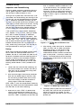
Figure
4-1 .
om
-c
se
or
H
MEASURE D I F FE R E NCE
BETWEEN COLUMNS
Figure
4-2.
" U " Tube Manometer
4.3
SECTION 5
AI R CLEANER AND AI R I NTAKE SYSTEM
w
w
-M
w
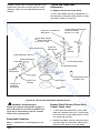
K series engi nes are equipped with a hig h-density
paper air cleaner element . Engines of some speci
fications are also equipped with an oiled foam
precleaner that surrounds the paper element . Re
fer to Fig u re 5-1.
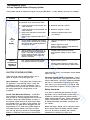
AIR CLEAN ER DISAS SEMBLY
Remove the wing nut and air cleaner cover.
2.
Remove the precleaner ( if so equipped) , pa
per element and seal .
3.
Remove the base screws , air cleaner base ,
gasket and hose .
P recleane r
If so equipped , wash and re-oil the precleaner
every 25 operating hours ( more often under ex
tremely dusty or dirty conditions) .
1.
Wash the precleaner in warm water and deter
gent .
2.
Rinse the precleaner thoroughly until all traces
of detergent are eliminated . Squeeze out ex
cess water (do not wring) . Allow precleaner to
dry.
3.
Saturate the precleaner with clean , fresh en
gine oil . Sq ueeze out excess oil .
4.
Rei nstall t h e precleaner over t h e paper ele
ment .
II
el
he
yW
1.
AIR CLEANER S ERVICE
-c
se
or
H
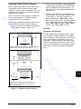
DRY ELEMENT �
Figure 5-1 . Air Cleaner Assembly - Exploded View.
(OPTI ON)
om
"'------ PRECLEANER
5. 1
Paper Element
Inspect Air Cleaner Compone nts
Every 1 00 operating hours (more often under ex
tremely dusty or dirty conditions) check the paper
element . Replace the element as follows :
Whenever the air cleaner cover is removed, or
when servicing the paper element or precleaner,
check the following components:
1.
w
Remove the precleaner (if so eq uipped) , ele
ment cover nut , element cover and paper ele
ment .
2.
Air Cleaner Base
Make sure it is secured
tightly to carburetor and is not bent or dam
aged .
2.
Element Cover and Element Cover N ut
w
yW
-M
NOT E : Do not wash the paper element or use
compressed air as this will damage the element .
Reinstal l the paper element .
4.
Install the precleaner (cleaned and oiled) over
the paper element .
5.
I nstall the a i r cleaner cover and wing nut .
Tighten wing nut. Make sure element is sealed
tightly against air cleaner base .
-
On
ment cover is not bent o r damaged . Check
that element cover nut is secured tightly to
seal element between air cleaner base and
element cover. Tighten nut to 50 in. l b .
torque. Refer t o Figu re 5-2 .
3.
3.
-
K 1 8 1 New Look engines only , make s u re ele
w
Replace a dirty, bent or damaged element with a
new genuine Kohler element. Handle new
elements carefully; d o not use if surfaces are
bent or d amaged .
1.
Breather Tube
Make sure it is sealed tightly
in the air cleaner base and breather cover.
-
NOT E : On Model K1 8 1 New Look engines of cer
tain specifications , the element cover may contact
the breather tube, making it impossible to maintain
crankcase vacuu m . To prevent this problem , cut
the end of the breather tube that protrudes
through the air cleaner base at approximately a 45
degree angle .
or
H
el
he
Breather
H ose
Air Cleaner
Base
om
-c
se
Paper
Element
Figure 5-2 . K 1 8 1 N ew Look, Air Cleaner Assembly.
5.2
NOTE : Damaged , worn or loose air cleaner com
ponents could allow u nfiltered air into the engine
causing premature wear and failure . Replace all
damaged or worn components .
OPTIONAL OIL BATH AIR CLEANER
w
w
If the engine has a n oil bath type air cleaner .
clean a n d service it after every 25 hours of opera
tion or more frequently if conditions warrant . Refer
to Figure 5-3 .
Remove the cove r . lift the element out of t he
bowl and drain the oil from the bowl .
2.
Thoroughly wash bowl and cover i n clean sol
vent . Swish the e lement in the solvent and al
low it to d ry.
-M
w
1.
NOTE : Do not use compressed air to d ry the ele
ment . The filtering material could be damaged .
Lightly re-oil the element with engine oil .
4.
Inspect base and cover gaskets . Replace if
damaged .
I nstall base gasket and place filter on air horn.
6.
Add engine oil to filter and fill to the OIL LEVEL
mark.
7.
Install filter element. cover gasket and cover.
Secure with wing nut finger tight only.
COOLIN G AIR I NTAKE SYSTEM
Effective cooling of an air cooled engine depends
on a n u nobstructed flow of air over the cooling
fin s . Air is drawn into the COOling shroud by fins
located on the flywheel . The blower housing , cool
ing shroud. air screen covering the flywheel and
cooling fins on the cylinder and cylinder head must
be kept clean and unobstructed at all times .
Never operate the engine with the blower housing
or cooling shroud-removed. These devices direct
air flow over the cooling fins .
NOTE : Some engines use a plastic grass screen
and some use meta l . The two are not interchange
able u nless other modifications are made to the
engine .
II
O I L L EV E L
Figure 5-3. Optional Oil Bath Air Cleaner.
om
-c
se
or
H
el
he
yW
3.
5.
5.3
SECTION 6
FUEL SYSTEM AN D GOVERNO R
w
chamber where it is compressed , then ign ited by
the spark plug .
The typical gasoline fuel system and related com
ponents include the f uel tank with vented cap ,
shutoff valve with screen , in-line fuel filte r , fuel
pump (some models) , carburetor and intercon
necting fuel line .
T roubleshooting
w
w
FUEL SYSTEM - GASOLIN E
yW
-M
Use the following procedure to check that fuel is
reaching the combustion chamber.
& WARNING:
Ope ration
Gasoline may be present in the carburetor and fuel
system. Gasoline is extremely flammable and it can
C h e c k for the f o l l owi n g :
A . Make sure the tank contains fuel.
Make sure the fuel cap vent i s open .
C . Make sure the fuel shutoff valve is open .
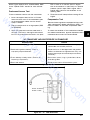
C h eck f o r fuel I n the c o m b u s t i o n c h a m ber.
2.
A . Disconnect the spark plug lead .
Conclusi9 n
D . Remove the spark plug and check for fuel at tip .
3.
A . Remove fuel line from inlet fitting at fuel pump .
om
-c
se
C . Crank the engine several times .
C h e c k for fuel f l ow from tank t o f u e l p u m p .
If there Is fuel at tip of spark plu g , fuel is reaching the combustion chamber.
If there Is no fuel at tip of spark plug , check for fuel from the
fuel tank. (Test 3 ) .
B . Close the choke on carburetor.
3.
the possibility of sparks from the ignition system.
or
2.
I f fuel does flow from line, check for faulty fuel pump.
(Test 4 ) .
If fuel does not flow from line , check for clogged fuel tank
vent, shutoff valve screen , and fuel lines.
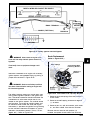
S . Hold line below bottom o f tank. Open shutoff
valve and observe flow.
If the fuel tank cap vent does not allow air to escape from
the tank, modify the vent for proper operation by cutting
1 132 " to 1 1 1 6 " off the bottom . Refer to Figure 6-1 .
4.
II
H
B.
connect and ground the spark plug lead to prevent
el
1.
explode if ignited. Keep sparks, open flames, and
other sources of ignition away from the engine. Dis
he
The fuel from the tank is moved through the
screen and shutoff valve , in-line filter and fuel
lines by the fuel pump (if so equipped) o r g ravity.
Fuel enters the carburetor float bowl and is moved
into the carburetor body where it is mixed with air.
The fuel-air m ixtu re is d rawn into the combustion
Test
Explosive Fuel!
C h e c k o peration o f f u e l p u m p
A . Remove fuel line from inlet fitting at carburetor.
B . Crank engine several times and observe flow .
4.
If fuel does not flow from line, check for clogged fuel lin e . If
line is unobstructed , fuel pump Is faulty and must be replace d .
I f fuel d o e s flow from fuel line, the carburetor probably Is
fault y . Refer to the · Carburetor " portion of this section .
6. 1
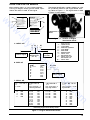
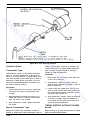
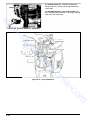
Operation
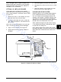
w
w
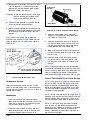
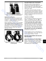
The mechanical fuel pump is operated by a lever
that rides on the engine camshaft . The lever
transmits a pumping action to the flexible d ia
phragm i nside the pump body . The pumping ac
tion draws fuel in through the inlet check valve on
the downward stroke of the diaphragm . On the
upward stroke , the fuel is forced out through the
outlet check valve . Refer to Figure 6-2 .
Cui Off
-M
w
�
�
'"
!;
�
��
�
VALVE S P R I NG/
e
D I APHRAGM S P R I NG
�
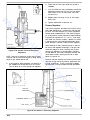
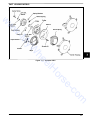
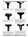
Figure 6-2. Mechanical Fuel P u m p .
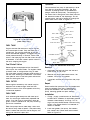
Removal
1.
Disconnect the fuel lines from the inlet and
outlet fittings of the pump.
2.
Remove the fillister head sems screws , flat
washers , fuel pump and gasket .
3.
If required , remove the fittings from the pump
body .
Repair
Plastic bodied fuel pumps are not serviceable and
must be replaced when faulty. Replacement
pumps are available in kits which include the
pump, mounting gasket and plain washers .
om
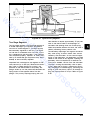
Installation
-c
Older fuel pumps have a metal body . Later mod
els have a body made of plastic. The plastic body
better insulates the fuel from t he hot engine , mini
mizing the chance of vapor lock.
�
MOU NT! NG GAS KET
�
se
All K series engines except the K9 1 have provi
sions for mounting a mechanically operated fuel
pump. If no fuel pump is mounted on these en
gines , a cover is placed over the pump mounting
pad on the crankcase.
D I AP H RAGM
or
H
FUEL PUMP
VAL V E PLATE S C REW
.., @) o
FUEL FILTER
Some engines covered by this manual may be
equipped with a see-through in line fuel filter.
When the i nterior of the filter appears to be dirty,
it should be replaced .
PUMP VAL V E
/
el
he
Some engines are equipped with a fuel shutoff
valve with a wire mesh screen . On engines without
a shutoff valve , a straight outlet fitting is used .
The wire mesh prevents relatively large particles in
the tank from reaching the carburetor. The shutoff
valve permits work on the fuel system without the
need for draining the tank.
VAL V E GAS KET
VA L V E S P R I N G
�
VAL V E RETA I N E R
P U MP CO V E R
/
PUMP VALVE �
Engine-mounted fuel tanks o n K series engines
are constructed of steel . They are fitted with a
vented cap . The venting properties of the cap
should be checked regularly . A clogged vent can
cause pressure buildup in the tank, which could
result in fuel spraying from the filler when the cap
is loosened . It can also cause a partial vacuum in
the tank, stopping the engine.
Fuel S hutoff Valve
W
0..,
C)
MATCH MARK
yW
FUEL TAN K
..
.
1 /32"-1/16"
Fig ure 6-1 . Fuel Tank Cap .
( " New Look" Only)
6.2
�
i/ ASS E MB L Y SC REW
1.
Fittings - Apply a small amount of Permatex®
Aviation Perm A Gasket (or equivalent gasoline
resistant thread sealant) to fittings . Turn fit
tings into pump six full t u rns; continue turn ing
fittings in the same direction u ntil desired di
rection is reached .
2.
Install new gasket , fuel pum p , flat washers ,
lock washers and fillister head sems screws .
Refer to Figure 6-3.
tor . This gives a leaner fuel-to-air mixt ure . Turning
the adjusting needles out (counterclockwise) in
creases the supply of fuel to the carburetor . This
gives a richer fuel-to-air mixture . Setting the nee
dles m idway between the lean and rich positions
will usually give the best results . Adjust the carbu
retor as follows :
w
1.
Plain Washer (2)
w
----
�
,j).. �
\
�
Fuel Pump
Mounting Flange
w
Fillister Head Sems
L Screws
(2)
NOTE : The tip of the low idle fuel and high idle fuel
adjusting needles are tapered to critical dimensions.
Damage to the needles and the seats in carburetor
body will result if the needles are forced .
yW
-M
2.
Figure 6-3. I nsta l l i n g Fuel P u m p .
Preliminary Settings: Turn the adjusting needles
out (cou nterclockwise) from lightly bottomed
according to the table shown in Figure 6-4 .
NOTE : Make sure that the fuel pump lever is posi
tioned above the camshaft . Damage to the fuel
pump and severe damage to the engine could re
sult if the lever is positioned below the camshaft .
3.
4.
he
Make sure that the flat washers are installed next
to the mounting flange to prevent damage from
the lock washers .
If a metal bodied pump was replaced by a pl astic
bodied p u m p , make sure that the old thick gasket
is discarded and the new thin gasket is used .
Torque screws to 37 - 45 i n . l i b .
4.
Con nect fuel lines t o in let a n d outlet fitti ngs .
Start the engine and run at half throttle for five
to ten min utes to warm u p . The engine m ust
be warm before making final settings (Steps 4 ,
5 , 6 , and 7) .
II
•
High Idle Fuel Needle Settin g : This adjustment
is required only for adjustable high idle ( main)
jet carburetors . If the carbu retor is a fixed
main jet type , go to step 5 .
Place the throttle into the .. fast " position . If possi
ble, place the engine u nder load .
el
3.
Gasoline may b e present in the carburetor and fuel
system. Gasoline is extremely flammable and it can
other sources of ignition away from the engine. Dis
connect and ground the spark plug lead to prevent
Now turn the adjusting needle i n (clockwise) . The
engine speed m ay increase , then it will decrease
as the needle is turned in (lean) . Note the position
of the need le.
om
-c
se
explode if ignited. Keep sparks, open flames, and
or
Explosive Fue l l
Turn the high idle fuel adjusting needle out (coun
terclockwise) from the prelim inary setting until the
engine speed decreases (rich) . Note the position
of the needle.
H
CARBURETOR - GASOLI N E
� WARNING:
With the engine stopped , turn the low idle fuel
adjusting needle in (clockwise) until it bottoms
lightly.
Set the adjusting needle midway between the rich
and lean settings. See Figure 6-5 .
the possibility of sparks from the ignition system.
5.
Low Idle Speed Setti n g : Place the throttle con
trol into the idl e " or .. slow " position . Set the
low idle speed to 1 2 00 rpm * (+ or - 75 rpm)
by turning the low idle speed adjusting screw
in or out. Check the speed using a tachome
ter.
Ii
Adj u stment
The carburetor is designed to deliver the correct
fuel/air mixture to the engine under all operating
conditions. Carburetors are set at the factory and
normally do not need adjustment . If the engine
exh ibits conditions like those found in the table
that fol lows , it may be necessary to adjust the
carburetor.
In genera l , t u rning the adjusting needles i n (clock
wise) decreases the supply of fuel to the carbure-
NOTE: The actual low idle speed depends on the
appl ication . Refer to the equipment manufacturer ' s
instructions for specific low idle speed settings.
The recom mended low idle speed for Basic En
gines is 1 200 rpm . To ensure best results when
setting the low idle fuel needle, the low idle speed
m ust not exceed 1 500 rpm .
6.3
P RELIMINARY S ETriNGS - K-SERIES MODELS
KOHLER ADJUSTABLE JET
Low Idle
High Idle
1 - 1 /2
1 - 1 /2
1 - 1 /2
1 -1 /4
2-1 /2
2-1 /2
2-1 /2
2- 1 /2
turns
turns
turns
turns
turns
turns
turns
turns
NOTE : Refer to publication TP2377B Carburetor
Reference Manual for
additional information .
NOT APPL.
NOT APPL.
NOT APPL.
2- 1 /2 turns
1 - 1 /4 turns
1 - 1 /4 turns
1 - 1 /2 turns
1 turn
2 turns
3 turns
3 turns
2 turns
2 turns
2 turns
3-1 /4 turns
3-1 /2 turns
* Includes .. New Look " Models
w
w
w
K9 1
K141
K161 *
K1 81 *
K24 1
K301
K32 1
K341
WALBRO FIXED JET
Low Idle
Figure 6-4. Preliminary Low Idle And High Idle Fuel Needle Settings.
yW
-M
6.
Low Idle Fuel Needle Setting : Place the throttle
into the " idle " or " slow " position .
Turn the low idle fuel adjusting needle out (coun
terclockwise) from the preliminary setting until the
engine speed decreases (rich ) . Note the position
of the needle .
Remove the float pin . float, fuel inlet needle .
baffle gasket a nd bowl gasket .
3.
Remove the fuel i nlet seat and inlet seat gas
ket . Remove the idle fuel and main fuel adjust
ing needles and springs . Remove the idle
speed adjusting screw and spring .
4.
Further disassembly t o remove the throttle and
choke shafts is recommended only if these
parts are to be replaced. Refer t o " Throttle
and Choke Shaft Replacement " later in this
section .
he
Now turn the adjusting needle in (clockwise) . The
engine speed may increase . then it will decrease
as the needle is turned in (lean) . Note the position
of the needle.
2.
Set the adjusting needle midway between the rich
and lean settings . See Figure 6-5.
el
7.
Recheck the low idle speed using a tachome
ter. Readjust the speed as necessary.
Disassembly
(Refer to Figure 6-7)
1.
Remove the bowl retaining screw. retaining
screw gasket and fuel bow l .
6. 4
Main Fuel
Needle
om
-c
se
Figure 6-5. Optimum Low Idle Fuel Setting.
�
or
Adj ust T o
M id p o i n t
H
Lea n
Idle
Speed
Screw
Figure 6-6. Kohler-Built Adjustable Jet
Carburetor.
Clea ning
'
WARNING: Flammable Solvents!
Carbure tor cleaners and solvents are
i
extremely fla mmable. Keep sparks ,
Idle Speed
Screw
flames and other sources of ignition
/
�
1
\�
a way from the area . Foffow the
cleaner manufacturer's warnings and
w
instructions on its proper and safe
use . Ne ver use gasoline as a clean
ing agent.
V
/
i
i
Main Fuel
Needle
spring
/' Carburetor
/'
Body
w
pri n g
All parts should be carefully cleaned using a car
buretor cleaner (such as acetone) . Be sure a l l
-M
w
7'��r--T:>WJ
g u m deposits a re removed from t h e following ar
eas :
Needle
Carburetor body and bore; especially the areas
where throttle plat e , choke plate and s hafts are
seated .
yW
Fuel I n let
Needle
e
he
NOTE : These areas can be cleaned using a p i ece
of fine wire in addition to cleaners . Be careful not
to enlarge the ports or break the cleaning w i re
NOTE: D o not s ubmerge carburetor i n cleaner o r
solvent when fiber or rubber seals are installed .
�
�
�
�
r�-�
�
FI oat
Float
Hi nge
6
�� '
'\
Float Pin
Fuel
Bowl ---l"""1
Bowl Retaining -�
. .
�___ B owI Retammg
Screw
Screw G asket
lH
Blow out a l l passages with compressed a i r .
��
Seat
Idle fuel and " off-idle" p orts in carburetor bore,
withi n the port s .
G asket
Fuel
I nlet
ports in main fuel adjusting needle and main
f uel seat.
Bowl
�
Float and float hinge.
Fuel bowl.
�
:
:::'
i�;L?- C�---�
�
/!; rZ
�
I dle Fuel
Figure 6-7. Kohler-Built Adjustable Jet
se
or
The cleaner may damage these seal s .
Carburetor - Exploded View.
I n s pect ion
Choke Plate Modification
1 .
Carefully i n spect all components and replace
The choke action has been changed on production
those that are worn or damaged .
carburetors to reduce the chances of over chok
I nspect the carburetor body for cracks . holes
K321 and K34 1 , both relief holes i n the choke
ing . On production carbu retors now used on the
2.
-c
and other wea r or damage .
plate have been enlarged to 1 1 /32" while on the
K24 1 and K3Q1 . one relief hole i s now 1 1 /32" and
3.
the other i s 3 / 1 6 " . If you find that the relief holes
are smaller than t h i s . enlarge them to these d i
float tabs .
mensions .
Ins pect the i n let needle and seat for wear or
g rooves .
5.
I nspect t h e tips o f the main and idle fuel ad
justing needles for wear or grooves .
om
4.
Inspect t h e float for dents o r holes . Check the
float hinge for wear and mi ssing or damaged
NOTE: When redrilling the holes , take the neces
sary precautions to p revent chips from entering
the engi n e .
Repair
Always use new gaskets when servicing and rein
Inspect t h e throttle and choke shafts and plate
stalling carburetors . Several repair kit s , which in
assemblies for wear or excessive play.
clude the gaskets and other components
I
are
6.5
Throttle And Choke Shaft
Replacement
available . Always refer to the Parts Manual for the
engine being serviced to ensure that the correct
carburetor repair kits and replacement parts are
ordered .
To Replace Throttle And Choke Shafts
Two kits are available that allow replacement of
the carburetor throttle and choke shafts of Kohler
carburetors. Refer to Figure 6-8.
w
w
Throttle Shaft/Lever Asse m b ly# 2-56x7/32" o r # 3-48x7l32"
B'ass Sc'ew
-M
w
~
Throttle Shaft -4 Styles
For Models K24 1 - K341 &
KT1 7- K T 1 9, 1 " Ca,b.
\
yW
Choke Shaft Bush i n g
,@
Choke Detent Bal l - Sp r i n g -- ,
\
C hoke Shaft Bush i n g
'Choke Shaf1
#2-56x7/32" o r
Choke Lever
(Reused)
#3-48x7/32"
Brass Screw
�/
C
�"
�
&
( Reused )
I
-
'�\J
'
I
-�
Th<attle Shaf1 B u s h i n g
Throttle P l ate ( Reused )
\
Throttle Shaft Bu s h i n g
I n sta l lation Tool
Bowl Gas ket
----- B affle Gaskel
Throttle And Choke Shaft Replacement Kits.
face hood) should be worn for any procedure involv
ing the use of compressed air, punches, hammers,
Remove Choke Plate and Choke Shaft;
Transfer Choke Lever
1.
To ensure correct reassembly. mark choke
plate and carburetor body with a marking pen .
Also take note of choke plate position i n bore
and choke lever position .
2.
Carefully and slowly remove the screws secur
chisels, drills, or grinding tools.
Disassemble Carburetor
Refer to " Disasse mbly " at the beginning of this
section .
om
Prevent Eye InJuryl
Suitable eye protection (safety glasses, goggles, or
6.6
_
-c
� WARNI NG:
6-8.
Throttle
Lever
se
Figure
_
�
:� � +
�
a
/� .
# 3- 48x7/32"
Brass Screws
\
# 3-48x7/32"
Brass Screws
,
or
H
iQ
?�l:1!,�
£
".�
I �"
�
�,
�
el
he
Choke Plate ( Reused)
2 Styles For Models
K91 - K 1 8 1 , 1 /2" Carbo
ing choke plate to choke shaft . Remove and
save the choke plate as it will be reused .
File off any bu rrs which may have been left o n
the choke shaft when t h e screws were re
moved . Place carburetor on workbench with
choke side down . Remove choke shaft ; the
detent ball and spring will fall out.
3.
4.
Note the position of the choke lever with re
spect to the cut out portion of the choke
shaft .
w
5.
w
Carefully g rind or file away the riveted portion
of the shaft . Remove and save the choke
leve r ; discard the old choke shaft .
6.
yW
-M
w
Attach the choke lever t o the new choke shaft
from the kit . Make sure the lever is installed
correctly as noted in step 4. Secure lever to
choke shaft as follows :
c.
Compare the old shaft with the new shafts in
the kit . Select the appropriate new shaft and
discard the old shaft.
d.
Attach throttle lever t o throttle shaft . Make
sure lever is installed correctly as noted in
step a .
e.
Apply Loctite t o threads of 1 #2-S6 x 7/32 "
brass screw (use #3-48 x 7/3 2 " screw if shaft
is 2-49/64 " long . Secure lever to shaft .
Drill Choke S haft Bores Using A Drill
Press
1.
Mount the carburetor body in a d rill press vise .
Keep the vise jaws slightly loose .
2.
Install a drill bit o f t h e following size in t h e drill
press chuck. Lower the bit (not rotating)
through both choke shaft bores ; then tighten
vise . This ensures accurate alignment of the
carburetor body with the d rill press chuck .
Models K9 1 - K1 8 1 ,' Apply Loctite to threads of 1
#2-56
x 7/32 " brass screw . Secure lever to shaft .
Models K24 1 - K34 1 ,. Apply Loctite to threads of 1
#3-48
x 7/32 " brass screw. Secure lever to shaft .
Remove Throttle Plate and Throttle Shaft;
Transfer Throttle Lever
To ensure correct reassembly, mark throttle
plate and carburetor body with a marking pen .
Also take note of the throttle plate position in
the bore and the throttle lever position.
2.
Carefully and slowly remove the screws secur
ing the t hrottle plate to throttle shaft . Remove
and save the throttle plate for reuse .
3.
File off any burrs that may have been left on
the throttle shaft when screws were removed.
Models K24 1 - K34 1 ( 1 " Carb . ) ; Use a 1 /4 " di
ameter drill bit .
Refer to Figure 6-9 .
S.
Remove and transfer the throttle lever as fol
lows :
Models K9 1 - K1 8 1 ( 1 12 " Carb. ) ,.
Carefully grind or file away t h e riveted portion of
the throttle shaft . Save the throttle shaft as it will
be used to install the new throttle shaft bushing .
Discard the t h rottle lever .
Mode/s K24 1 - K34 1 ( 1 " Carb . ) ;
b.
Note the position of the throttle lever with re
spect to the cutout portion of the throttle
shaft.
Carefully grind o r file away the riveted portion
of the shaft . Remove t he throttle lever.
om
-c
se
Remove throttle shaft from carbu retor body.
Remove and discard the foam rubber dust seal
from the throttle shaft .
or
4.
H
el
NOTE: Failu re to remove burrs from the throttle
shaft may cause permanent damage to carburetor
body when shaft is removed.
a.
II
he
1.
Models K9 1 - K 1 8 1 ( 1 12 " Carb . ) ; Use a 7/32 " di
ameter drill bit.
Figure 6-9 . Aligning/Drilling Carburetor Body.
3.
4.
Install a 1 9/64" drill bit i n the chuck. Set drill
press to a low speed suitable for aluminu m .
Drill slowly to ensure a good finish .
Ream the choke shaft bores to a final size of
For best results use a piloted 5 / 1 6 "
reamer.
5/1 6 " .
S.
Blow out all metal chips using compressed air.
Thoroughly clean the carburetor body in carbu
retor cleaner.
6.7
2.
Install Choke S haft Bushings
1.
Install screws in the tapped holes that enter
the choke shaft bores u ntil the screws bottom
lightly. Refer to Figure 6- 1 0 .
Models K9 1 - K 1 8 1 ( 1 /2 " Carb . ) ; Use the old
throttle shaft removed previously .
Models K14 1 - K34 1 (1 " Carb . ) ; Use one of the
remaining new throttle shafts from the kit .
3.
w
w
2 . Coat the outside surface of the kit-supplied
choke shaft bushings with Loctite from the kit .
Carefully press the bushings into the carbure
tor body using a smooth-jawed vise . Stop
pressing when bushings bottom against
screws .
Coat the outside surface of the throttle shaft
bushing with Loctite from the kit . Slip the
bushing over the shaft . Using a vise and the
installation tool from the kit , press the bushing
into the counterbore until it bottoms in the car
buretor body. Refer to Figure 6- 1 1 .
-M
w
Models K9 1 - K1 8 1 ( 1 /2 " Carb . ) ; Make sure the
bushing is pressed below the surface of the large
choke shaft boss u ntil the bushing bottoms against
screw.
3.
Install a throttle shaft (without throttle lever) in
carburetor body to use as a pilot :
Allow Loctite to " set " for 5 to 1 0 minutes ,
then remove screws .
el
he
yW
Fig ure
Installing Choke Shaft Bushings.
Install new choke shaft in bushings . Rotate
shaft and check that it does not bind .
6.
Remove choke shaft and allow Loctite to " set "
for an additional 30 minutes before proceed
ing .
Wipe away any excess Loctite from bushings
and choke shaft .
Install Throttle S h aft Bushing
1.
Make sure the dust seal counterbore in the
carburetor body is thoroughly clean and free of
chips and burrs .
6.8
5.
I nstall the new throttle shaft and lever i n carbu
retor body . Rotate the shaft and check that it
does not bind.
NOTE : If binding occurs , locate the cause and correct
before proceeding . Use throttle shaft to align bushing
if necessary.
6.
Remove the shaft and allow the Loctite to
" set " for an additional 30 minutes before pro.
ceeding .
7.
Wipe away all excess Loctite from bushing and
throttle shaft .
om
5.
Allow the Loctite to " set " for 5 to 1 0 minutes ,
then remove the throttle shaft .
-c
NOTE : If binding occurs , locate and correct the
cause before proceeding . Use choke shaft to align
bushings if necessary .
4.
se
4.
6-1 0.
Installing Throttle Shaft Bushing.
or
H
Figure
6-1 1 .
I nstall Detent S pring and Ball, Choke
S haft and Choke Plate
1.
Install new detent spring and ball in carburetor
body in the side opposite the choke lever.
2.
Compress detent ball and spring and insert
choke shaft through bushings . Make sure the
choke lever is on the correct side of the car
bu retor body. Refer to Figure 6-1 2 .
3.
4.
R eassembly
Operate the choke lever. Check that there is
no binding between choke plate and carburetor
bore. Loosen screws and adjust plate as nec
essary: then tighten screws .
2.
w
w
Attach c hoke plate t o choke shaft. Make sure
marks are aligned and plate is positioned prop
erly in the bore . Apply Loctite to threads of 2
#3-48 x 7/3 2 " brass screws . Install screws so
that they are slightly loose.
1.
Install the fuel inlet seat gasket and fuel inlet
seat into carburetor body. Torque seat to
35/45 in. l b .
3.
Install the fuel inlet needle into i nlet seat . In
stall float and slide float pin through float hinge
and float hinge towers on carburetor body.
Set float level: Invert carburetor so the float
-M
w
tab rests on the fuel inlet needle . There should
be 1 1 /64" (+- 1 /3 2 " ) clearance between the
machined surface of body and the free end of
float . Bend the float tab with a small screw
driver to adjust . Refer to Figure 6-1 3 .
Bend Tab
To Adjust
yW
II
el
he
Figure 6-1 2 . Installing Choke Shaft.
I nstall Throttle S haft a nd Throttle Plate
1
.
3.
Apply finger pressure to throttle shaft to keep
it firmly seated against pivot in carburetor
body. Rotate the throttle shaft until the throttle
plate fully closes the bore around its perime
ter: then tighten screws.
4.
Reassemble Carburetor
Refer to the following " Reassembly " portion of this
section .
normal operating position a nd allow float to
drop to its lowest leve l . The float drop should
be limited to 1 - 1 /32" between the machined
surface of body and the bottom of the free
end of float . Bend the float tab with a small
screwdriver to adj ust . Refer to Figure 6-1 4 .
Bend Tab
��...,J..A/ To Adjust
om
Operate t h e throttle lever and check that the
throttle plate does not bind i n the bore .
Loosen screws and adjust plate if necessary;
then tighten screws securely.
Set float drop: Turn the carburetor over t o its
-c
Attach t hrottle plate t o throttle shaft. Make
sure marks are aligned and plate is positioned
properly in the bore. Apply Loctite to threads
of 2 #3-48 x 7/32 " brass screws . Install
screws so that they are slightly loose.
4.
se
2.
Figure 6-1 3 . Setting Float Level.
or
H
Install t hrottle shaft i n carburetor with cutout
portion of the shaft facing out .
I nverted Carburetor
Figure 6-1 4. Setting Float Drop.
6.9
5.
Check float-to-float hinge tower clearance:
Invert the carburetor so the float tab rests on
the fuel inlet needle . Insert a 01 0 feeler
gauge between float and float h inge towers. If
the feeler gauge cannot be inserted , or there
is interference between the float and towers ,
file the towers to obtain the proper clearance .
Refer to Figure 6-1 5 .
.
"
w
w
6.
7
.
This section covers the idle adjustment , disassem
bly , cleaning , inspection , repair, and reassembly
of the Walbro-built, side draft, fixed/adjustable
main jet carburetors.
Idle Fuel
Idle Speed
Adjusting Screw
Install the fuel bowl so it is centered on the
baffle gaske t . Make sure the baffle gasket and
bowl are positioned properly to ensure a good
seal .
-M
w
8.
Install the bowl gasket and baffle gasket . Posi
tion baffle gasket so the inner edge is against
the float hinge towers.
WALBRO FIXED/ADJU STABLE
CARBURETOR
I nstall the bowl retaining screw gasket and
bowl retaining screw Torque screw to 50/60 in.
lb.
0.010" Feeler Gauge
(B.th S
SJ
t
el
he
Figure 6-1 6. Fixed Main Jet Carburetor.
£ WARNING: Accidental Starts!
Before servicing the carburetor, engine, or equip
or
H
File If
Necessary
yW
Float
ment, always remove the spark plug leads to prevent
Inverted Carburetor
Float Hinge Towers
(On Carburetor Body)
£ WARNING: Explosive Fuel!
se
Figure 6-1 5 . Checking Float Clearance.
the engine from starting accidentally. Ground the
leads to prevent sparks that could cause fires.
Gasoline may be present in the carburetor and fuel
system. Gasoline is extremely flammable and its
NOTE : The ends of adjusting needles are tapered
to critical dimensions. Damage to needles and
seats will result if needles are forced .
vapors can explode if ignited. Keep sparks, open
flame, and other sources of ignition away from the
area to prevent the possibility of fires or explosions.
om
I nstall the idle speed adjusting screw and
spring . I nstall the idle fuel and main fuel ad
justing needles and spring s . Turn the adjusting
needles clockwise until they bottom lightly .
-c
9.
£ WARNING: Prevent Eye Injury!
Suitable eye protection (safety glasses, goggles, or
1 0 . Reinstall the carburetor t o the engine using a
new gasket .
face shield) should be worn for any procedure in
volVing the use of compressed air, punches, ham
mers, chisels, drills, or grinding tools.
11 . Adjust the carburetor as outlined under the
" Adjustment " portion of this section .
6. 1 0
" N O T E T " ese will be 0 " el:her :ne l O D I t " 'ottle
Date Code*
leve-: side of mounting f ange as s"own, c I o n
:he bot:ol'1 (fuel bow l ) s ee 0' mo u � l r n g f l a n g e
Throttle Leverl
Shaft Assembly
Idle Fuel Adjusting
Needle And Spring
w
w
Welch Plugs
Choke Leverl
Shaft Assembly
-M
w
/
Fuel Bowl
I
Choke Detent
Ball And Spring
yW
Mounting Flange
� Fuel Bowl Retaining
Idle Speed Adj usting
Screw And Spring
Screw And Gasket
II
Fuel Bowl
Gasket
el
he
Float
Throttle P late
or
H
"Off-Idle"
Port
Adjusting Tab
I
Float Drop
Limiting Tab
(Non-Adjustable)
-c
se
Bleed
Bowl Vent
om
Nozzle
Air Bleed
Air Clea ner
Mounting Surface
I dle Fuel
I n let
Figure
I
I
I
I
I
I
6-1 7.
Fuel I nlet
Needle
Major Components And S e rvice Locations - Typical Fixed Jet Carburetor.
6. 1 1
•
TROUBLESHOOTING
If engine troubles are experienced that appear to
be fuel system related , check the following areas
before adjusting or disassembling the carburetor.
•
Make sure the fuel tank is filled with clean ,
fresh gasoline.
•
w
w
Make sure the fuel tank cap vent is not
blocked and that it is operating properly .
•
-M
w
Make sure fuel is reaching the carburetor. This
includes checking the fuel shut-off valve , fuel
tank filter screen , in-line fuel filter, fuel lines,
and fuel pump for restrictions or faulty compo
nents as necessary.
Make sure the ignition system , governor sys
tem , exhaust syste m , and throttle and choke
controls are operating properly.
If , after checking the items listed above , starting
problems or other conditions similar to those listed
in the following table exist , it may be necessary to
adjust or service the carburetor.
Engine starts hard , or
runs roughly or stalls at
idle speed .
1.
E ngine runs rich .
(Indicated by black ,
sooty exhaust smoke ,
misfiring , loss of
speed and power ,
governor hunting , or
excessive throttle
opening . )
2a . Choke partially closed during operation . Check the choke lever and
linkage to ensure choke is opening after warm-up.
Idle fuel mixture or idle speed are improperly adjusted. Adjust the
idle speed screw , then adjust idle fuel needle .
yW
2.
•
Make sure the air cleaner element is clean
and all air cleaner components are fastened
securely.
Possible Cause/Probable Remedy
Condition
1.
•
Make sure the carburetor is. securely fastened
to the engine using gaskets in good condition.
b . Idle fuel mixture is improperly adjusted. Adjust idle fuel needle .
el
he
c . Float level set too hig h . With fuel bowl removed and carburetor inverted , set exposed surface of float parallel with the bowl gasket
surface of carburetor body.
d . Dirt under fuel inlet needle. Remove needle . Clean needle and seat
and blow with compressed air.
e. Bowl vent or air bleeds plugged . Remove fuel bowl , idle fuel adjusting needle , and welch plugs . Clean vent , ports , and air bleed s . Blow
out all passages with compressed air.
or
H
f. Fuel bowl gasket leaks . Remove fuel bowl and replace gasket .
g . Leaky , cracked . or damaged float. Submerge float to check for
leaks .
3.
3a. Idle fuel mixture i s improperly adjusted . Adjust idle fuel needle .
Fuel leaks from
carburetor.
4a. Float level set too hig h . See Remedy 2c.
b . Float level set too low . With fuel bowl removed and carburetor inverted , set exposed surface of float parallel with the bowl gasket
surface of carburetor body.
se
c . Idle holes plugged ; dirt in fuel delivery channels. Remove fuel bowl .
idle fuel adjusting needle. main fuel jet , and welch plugs. Clean all
passages and blow out with compressed air.
b. Dirt under fuel inlet needle. See Remedy 2d .
om
-c
4.
Engine runs lea n .
(Indicated by misfiring ,
loss of speed and
power. governor hunting . or excessive
throttle opening . )
c . Bowl vent plugged . Remove fuel bowl and clean bowl vent . Blow out
with compressed air.
d. Float is cracked or damaged . Replace float .
e . Bowl retaining screw gasket damaged . Replace gasket .
f . Bowl retaining screw is not tightened. Torque screw to specifications.
6. 1 2
In general , turning the adjusting needles I n (clock
wise) decreases the supply of fuel to the carbure
tor. This gives a leaner fuel-to-air mixture . Turning
the adjustfng needles out (counterclockwise) in
creases the supply of fuel to the carburetor. This
gives a richer fuel-to-air mixture . Setting the
needles midway between the lean and rich posi
tions will usually give the best results.
I dle Speed
Adjusting Screw
I
w
Adjust the carburetor as follows :
1.
I dle Fuel
Adjusting Needle
yW
-M
w
w
2.
3.
Figure 6-1 8. Fixed Main Jet Carburetor.
4.
Preliminary Settings: Turn the adjusting nee
dles out (counterclockwise) from lightly bot
tomed according to the table shown in Figure
6-20 .
Start the engine and run a t half throttle for five
to ten minutes to warm u p . The engine must
be warm before making final settings (Steps 4 ,
5 , 6 , and 7) .
High Idle Fuel Needle Setting: This adjustment
is required only for adjustable high Idle (main)
Jet carburetors. If the carburetor is a fixed main
Jet type, go to step 5 .
II
he
Place t h e throttle into the " fast " position . If possi
ble , place the engine under load .
Lean
Adjust
To M idpoint
With the engine stopped , turn the low idle fuel
adjusting needle in (clockwise) u ntil it bottoms
lightly.
el
Turn the high idle fuel adjusting needle out (coun
terclockwise) from the preliminary setting until the
engine speed decreases (rich) . Note the position
of the needle.
H
Now turn the adjusting needle i n (clockwise) . The
engine speed may increase, then it will decrease
as the needle is turned in (lean ) . Note the position
of the needl e .
Figure 6-1 9. Carburetor Adjustment.
CARBURETOR ADJ USTMENT
NOT E : The tip of the low idle fuel and high idle
fuel adjusting needles are tapered to critical di
mensions . Damage to the needles and the seats
in carburetor body will result if the needles are
forced.
Low Idle Speed Settin g: Place the throttle
control into the " idle " or " slow" position. Set
the low idle speed to 1 200 rpm * (+ or - 75
rpm) by turning the low idle speed adjusting
screw in or out. Check the speed using a ta
chometer.
om
-c
se
5.
or
Set t h e adjusting needle midway between t h e rich
and lean settings. See Figure 6-2 1 .
" NOTE : The actual low idle speed depends on the
applicatio n . Refer to the equipment manufacturer' s
instructions f o r specific l o w idle speed settings.
The recommended low idle speed for Basic En
gines is 1 200 rpm . To ensure best results when
setting the low idle fuel needle. the low idle speed
must not exceed 1 500 rpm .
6. 1 3
PRELI M I NARY S En"INGS
K-SERIES MODELS
KOHLER ADJUSTABLE JET
High Idle
1 - 1 /2 turns
1 - 1 /2 turns
1 - 1 /2 turns
1 - 1 /4 turns
2 - 1 / 2 turns
2 - 1 / 2 turns
2 - 1 / 2 turns
2 - 1 / 2 turns
1 turn
1 turn
1 - 1 /4 turns
2 turns
3 turns
3 turns
2 turns
2 turns
2 turns
3-1 /4 turns
3- 1 /2 turns
2- 1 /2 turns
2-1 / 2 turns
3 turns
w
w
Low Idle
-M
w
K91
K1 4 1
K1 6 1 *
K181 *
K24 1
K301
K32 1
K34 1
KT1 7
KT1 9
K582
WALBRO
FIXED J ET
Low Idle
NOT APPL.
NOT APPL.
NOT APPL.
2-1 / 2 turns
1 - 1 /4 turns
1 - 1 /4 turns
1 - 1 /2 turns
1 turn
1 -1 /4 turns
1 -1 /4 turns
NOT APPL.
WALBRO ADJUSTABLE JET
Low Idle
High Idle
2 B DETERMD
NOT APPL .
2 B DETERMD
2-1 / 2 turns
1 -3/4 turns
1 -3 /4 turns
2 B DETERMD
2 B DETERMD
1 - 1 /4 turns
1 -1 /4 turns
2 B DETERMD
2 B DETERMD
NOT APPL.
2 B DETERMD
3 /4 turn
1 - 1 /8 turns
1 -1 /8 turns
2 B DETERMD
2 B DETERMD
1 - 1 /4 turns
1 turn
2 B DETE RMD
yW
* Includes .. New Loo k " Models
Figure 6-20. Prel iminary Low Idle And High Idle Fuel Needle Settings.
6.
Low Idle Fuel Needle Setting: Place the
th rottle into the " idle " or " slow " position .
Lean
el
he
Turn the low idle fuel adjusting needle out (coun
terclockwise) from the preliminary setting u ntil the
engine speed decreases (rich) . Note the position
of the needle.
Set the adjusting needle midway between t h e rich
and lean settings . See Figure 6-2 1 .
7.
Figure 6-21 . Optimum Low Idle Fuel Setting.
om
-c
se
Recheck the low idle speed using a tachome
ter. Readjust the speed as necessary.
or
H
Now turn the adjusting needle in (clockwise) . The
engine speed may increase, then it will decrease
as the needle is turned in (lean ) . Note the position
of the need l e .
Adj u st To
M id po i n t
6. 1 4
DISASS EMBLY
Refer To Fig ures
6-1 7
and 6-22 .
Throttle shaft
w
w
Breather fitting
��
��
Throttle plate screws
I��1
/:;,
��
-M
w
Carburetor Assembly
Throttle plate
�
�
@
�
ldle adjusting
need le
I Idle need le
� spring
,'\. \'!I V-./"/
%�
�
0
)\�
�
"
¢i'
/r� �C)
Choke spring
Choke ball
Choke plate _
�
\)
C)
\)'I!i
\S
\J
�,
�
�
�
.
High speed
""' needle
�
�"""Throttle adjusting
spring
Thr;'tle adjustin g
\ screw
f.l
Mai.n needle
sprmg
"Choke shaft
•
�"'-Main
"'" Jet
,/ � Bowl gasket
II
Float Kit �
el
he
yW
Choke plate screws
0
S
- Fuel bOWI
� - Gasket for bowl retainer screw
or
H
� -- Bowl retainer screw
Figure 6-2 2. Walbro Fixed/Adj ustable Jet Carburetor - Exploded View
Remove the bowl retaining screw , retaining
screw gasket , and fuel bowl .
2.
Remove the bowl gasket , float pin, float , and
fuel inlet needle .
Remove the idle fuel adjusting needle and
spring . Remove the idle speed adjusting screw
and spring .
4.
Remove the main fuel jet .
5.
I n order t o clean the " off-idle " ports and the
bowl vent channel thoroughly, the welch plugs
covering these areas must be removed . Use
Do Not Allow
Tip To Strike
Carburetor Body
�
-�
__
\
ry Out Plug
om
3.
Tool #K01 01 8
-c
CAUTION : To prevent damage to the carburetor, do
not attempt to remove the fuel inlet seat
as it is not serviceabl e . Replace the carbu
retor if the fuel inlet seat is damaged .
tool No. K01 0 1 8 and the following procedure
to remove the welch plugs . Refer to Figure
6-23 .
se
1.
)
Pierce Plug
With Tip
j
..J"':lI'-':::
=---::: w
-e-lch -PI U-9---
....___
Figure 6-23. Removing Welch Plugs.
6. 1 5
A.
Pierce t h e welch plug with t h e t i p o f t h e tool .
reassembly (refer to Figure 6-25) . Also take
note of the choke plate position in bore , and
the position of the choke lever.
CAUTION : To prevent damage to the carburetor , do
not allow the tool to strike the carburetor
body.
B.
Pry out the welch plug using the tool .
Throttle And Choke S haft Removal
w
w
Further disassembly to remove the throttle shaft
and choke shaft is recommended only if these
parts are to be cleaned or replaced .
Throttle S haft Removal
Because the edges of throttle plate are bev
eled , mark the throttle plate and carburetor
body with a marking pen to ensure correct
reassembly (refer to Figure 6-24) . Also take
note of the throttle plate position in bore , and
the position of the throttle lever.
Figure 6-25. Marking Choke Plate And
Carburetor Body.
2.
Carefully and slowly remove the screws secur
ing the choke plate to choke shaft . Remove
the choke plate.
3.
File off any burrs which may have been left on
the choke shaft when the screws were re
moved . Do this before removing the choke
shaft from carburetor body.
he
yW
-M
w
1.
4.
3.
File off any burrs which may have been left on
the throttle shaft when the screws were re
moved . Do this before removing the throttle
shaft from carburetor body.
4.
Remove the throttle lever/shaft assembly with
foam d ust seal from carburetor body.
Choke Shaft Removal
1.
Because the edges of choke plate are bev
eled , mark the choke plate and carburetor
body with a marking pen to ensure correct
6. 1 6
Choke Lever/
Shaft Assembly
om
-c
se
Carefully a n d slowly remove the screws secur
ing the throttle plate to throttle shaft . Remove
the throttle plate .
or
2.
H
el
Figure 6-24. Marking Throttle Plate And
Carburetor Body.
Rotate the choke shaft until the cutout portion
of shaft is facing the air cleaner mounting sur
face (refer to Figure 6-26) . Place the carbure
tor body on work bench with choke side down .
Remove the choke lever/shaft assembly from
carburetor body ; the detent ball and spring will
drop out .
Figure 6-26. Removing Choke Lever/Shaft.
REPAIR
CLEANING
£ WARNING: Flammable SolventsI
Carburetor cleaners and solvents are extremely
flammable. Keep sparks, flames and other sources
of ignition away from the area. Follow the cleaner
manufacturer's warnings and instructions on its
w
w
proper and safe use. Never use gasoline as a
cleaning agent.
-M
w
All parts should be carefully cleaned using a car
buretor cleaner (such as acetone) . Be sure all
gum deposits are removed from the following
areas :
•
Carburetor body and bore; especially the
•
Idle fuel and "off-idle" ports i n carburetor
bore, main jet, bowl vent, and fuel inlet seat.
areas where the throttle plate . choke plate .
and shafts are seated .
Always use new gaskets when servicing and rein
stalling carburetors . Repair kits are available which
include new gaskets and other components. These
kits are described below.
Components such as the throttle and choke shaft
assemblies, throttle plate , choke plate , idle fuel
needle, main jet, and others , are available sepa
rately.
Refer to the appropriate Parts Manual to ensure
the correct carburetor repair kits. and replacement
parts are ordered .
REASSEMBLY
Throttle S haft Installation
yW
1.
I nstall the foam dust seal on throttle shaft . I n
sert t he throttle lever/shaft assembly into car
buretor body with the cutout portion of shaft
faCing the carburetor mounting flange .
2.
I nstall the throttle plate t o throttle s haft . Make
sure the plate is positioned properly in bore as
marked and noted during disassembly (the
numbers stamped on plate should face the
carburetor mounting flange) . Apply Loctite®
#609 to threads of 2 plate retaining screws.
I nstall screws so they are slightly loose .
•
Float and float hinge.
•
Fuel Bowl.
•
Throttle plate, c hoke plate, throttle shaft,
and choke shaft.
Apply Pressure When
Tightening Screws
Carefully inspect all components and replace those
that are worn o r damaged .
•
•
Inspect the carburetor body for cracks , holes ,
and other wear o r damage.
Inspect the float for cracks or holes . Check
the float hinge for wear, and missing or dam
aged float tabs.
Inspect the fuel inlet needle for wear or
grooves.
I n spect the tip of the idle fuel adjusting needle
for wear or grooves.
Inspect the throttle and choke shaft and plate
assem blies for wear or excessive play.
om
•
Throttle Lever/
Shaft Assembly
-c
•
Apply finger pressure t o the throttle lever/shaft
to keep it firmly seated against pivot in carbu
retor body. Rotate the throttle shaft until the
throttle plate fully closes the bore around its
entire perimeter; then tighten screws. Refer to
Figure 6-2 7 .
se
I N SPECTION
3.
or
H
CAUTION : Do not submerge the carburetor in cleaner
or solvents when fiber. rubber, or foam
seals or gaskets, or the fuel inlet needle
are installed . The cleaner may damage
these parts.
•
6
el
he
NOTE: These areas can be cleaned using a piece
of fine wire in addition to cleaners . Be careful not
to enlarge the ports, or break the cleaning wire
within ports . Blow out all passages with com
pressed air .
Figure 6-27. Installing Throttle LeverlShaft.
4.
Operate the throttle lever; check for binding
between the throttle plate and carburetor bore .
Loosen screws and adjust throttle plate as
necessary; then torque screws to 8/ 1 2 in. lb.
Choke S haft Insta llation
1.
I nstall the detent spring and ball into the car
buretor body.
6. 1 7
TOOI 'KO�
CAUTION : If the detent ball does not drop through the
tapped air cleaner base screw hole by its
own weight , do not force it. Forcing the
ball could permanently lodge it in the hole .
Install the ball through the choke shaft
bore instead .
Compress the detent ball and spring . I nsert
the choke lever/shaft assembly i nto carburetor
body with the cutout portion of shaft facing the
air cleaner m ounting surface (refer to Figure
6-28) . Make sure the choke l ever is on the
correct side of carburetor body .
w
w
2.
'"
� �"New Welch
Figure 6-29. Installing Welch Plugs.
C. After welch plugs are installed , seal the ex
posed surface with glyptal (or an equivalent
sealant) . Allow the sealant to dry.
2.
I nstall the main fuel jet .
3.
Install fuel i nlet needle into i nlet seat . Install
float and slide f loat pin through float hinge and
float h inge towers on carburetor body.
Install the choke plate t o choke shaft . Make
sure the plate is positioned properly in bore as
marked and n oted during d isassembly. (The
numbers stamped on plate should face the air
cleaner mounting surface and be upright . ) Ap
ply Loctite® #609 to threads of 2 plate retain
ing screws . Install the screws so they are
slightly loose .
Bend Tab
To Adjust
I
I
+
Parallel
t
..
--
Figure 6-30 . Setting Float Level.
om
If the welch plugs have been removed for
cleaning , new welch p l ugs m ust be installed .
Use tool No. K01 0 1 7 and the following proce
dure to i nstall the welch plugs .
-c
Carburetor Reassembly
1.
)I
)
se
Operate the choke lever; check for binding
between the choke plate and carburetor bore .
Adjust plate as necessary; then torque screws
to 8 / 1 2 in. lb.
or
H
4.
Set Float Level: I nvert the carburetor s o the
float tab rests on the fuel inlet needle. The
exposed surface of float should be parallel
with the bowl gasket surface of the carburetor
body (exposed , free end of float . 690 " / . 720"
from bowl gasket surface) . Refer to Figure
6-30.
el
he
4.
Figure 6-28. Installing Choke Lever/Shaft.
3.
Plug
NOTE : If a commercial sealant is not available .
fingernail polish can be used .
yW
-M
w
Compress B a l l
A n d Spring
Carburetor Body
Bend the f loat tab with a small screw driver to ad
just .
A.
Position t h e carburetor body securely with the
welch plug cavities to the top .
5.
B.
Place a new welch plug into the cavity with the
raised portion up. Use the end of the tool that
is about the same size as plug and flatten the
plu g . Do not force the plug below the top sur
face . Refer to Figure 6-29 .
Install a new bowl gasket and the fuel bowl .
Make sure the bowl gasket and bowl are cen
tered and positioned properly to ensure a
good seal .
6.
I nstall a new bowl retai ning screw gasket and
the bowl retaining screw. Torque screw to
6.1 8
45/55 in. lb.
7.
Install the idle speed adjusting screw and
spring .
4.
Install t h e new h i g h altitude main fuel jet and
torque to 1 2/ 1 6 In. lb.
8.
Install t h e idle fuel adjusting needle a n d spring .
Turn the adjusting needle in (clockwise) until it
bottoms l i g htly.
5.
Reinstall the fuel inlet needle , float , and float
pin .
6.
Install the new bowl gasket from kit and the
fuel bowl . Make sure the bowl gasket and bowl
are centered and positioned properly to ensure
a good seal .
7.
Install the new bowl retaining screw gasket
from kit and the bowl retaining screw. Torque
screw to 45/55 in. lb.
8.
Reinstall the carburetor and air cleaner to en
gine as necessary using the new gaskets from
kit.
w
CAUTION : The tip of the idle fuel adjusting needle is
tapered to critical dimensions . Damage to
the needle and the seat in carburetor body
will result if the needle is forced .
Turn the idle fuel needle out (counterclock
wise) from lightly bottomed according to the
instructions in the Adjustment " section of this
Bul letin .
II
w
w
9.
HIGH ALTITUDE OPERATION (FIXED J ET)
yW
-M
When operating the engine at high altitudes the
main fuel mixture tends to get overrich . An over
rich mixture can cause conditions such as black .
sooty exhaust smoke , misfiring , loss of speed and
power, poor fuel economy, and poor o r slow gov
ernor response .
High Altitude Jet I nstal lation (Fixed Jet)
1.
The idle speed of some vibro-mounted K34 1 AQS
engines has been increased to allow smoother OPeration at low idle and an anti-dieseling solenoid
has been added to prevent dieseling during shutdown at the higher idle speed . If called upon to
adjust the idle on any K34 1 AQS engine with this
solenOid , use the following procedure. Refer to
Figure 6-3 1 .
II
•
he
To , compensate for this , a special high altitude
main fuel jet is available for each carburetor . The
high altitude m ain fuel jet is sold in a kit which in
cludes the jet and necessary gaskets .
I DLE ADJUSTMENT PROCEDURE FOR
K341 AQS ENGINES WITH ANTI-DIESELING
SOLENOID
el
Remove the fuel bowl retaining screw. retaining screw gasket . fuel bowl, and bowl gasket .
STEP 1
IDLE FUEL M IXTURE ADJUSTMENT: With
engine stopped . turn the idle fuel adjusting screw
all the way in (clockwise) until it bottoms lightly
then back out 1 12 turn.
Remove the float pin , float , and fuel inlet
needle .
3.
Remove t h e existing main fuel jet .
-
om
-c
se
or
2.
STEP 2
I DLE SPEED ADJUSTMENT: Start engine
and check idle speed with a hand tachometer.
Idl e , no load , speed should be 2 1 00 RPM . To set
the idle speed , loosen the jam nut on the anti
dieseling solenoid and turn the solenoid in or out
until 2 1 00 RPM idle speed is attained - retighten
jam nut to lock solenoid in position .
H
NOTE : If necessary, remove the air cleaner and
carburetor from engine to make fuel bowl removal
easier.
6. 1 9
SO L E NO I D , A NT I - D I ES E L I NG
( 45 435 01 )
yW
-M
w
w
w
THROTTLE
L I N KAGE
he
�
*NOTE: Make sure idle speed scre� on carbure tor has been
turned counterc lockwi s e unti l i t no longer contacts the
throttle bracke t - - this a l lows the throt t le p late to c lose fu l ly .
Automatic Chokes
el
Figure 6-31 . Anti-Dieseling Solenoid.
1.
Loosen adjustment lock screw on choke body.
This allows the position of adjustment to be
changed .
2.
Moving adjustment bracket downward will in
crease the amount of choking . U pward move
ment will result in less choking .
3.
After adjustment is made , tighten adjustment
lock screw .
1.
Move choke arm until hole in brass shaft lines
up with slot in bearings .
2.
Insert #43 drill ( . 089) and push all the way
down to engine manifold to engage in notch in
base of choke unit.
3.
Loosen clamp bolt choke lever, push arm up
ward to move choke plate toward closed posi
tion . After desired position is attained , tighten
clamp bolt then remove dril l .
4.
After replacing air cleaner, check for evidence
of binding in linkage , adjust as needed . Be
sure chokes are fully open when engine is at
normal operating temperature .
om
-c
se
Adjustment
Adjustment
or
The automatic choke is a heat sensitive thermos
tatic unit. At room temperatu re , choke lever will
be set in a vertical position . If engine should fail to
start when cranked , adjust choke lever by hand to
determine if choke setting is too lean or too rich .
Once this has been establ ished , adjustment can
be made to remedy situation .
H
Thermostatic Type
made o n cold engine . If starting i n extreme cold ,
choke should be in full closed position before en
gine is started . A lesser degree of choking is
needed in milder temperatures .
THERMO-ELECTRIC AUTOMATIC CHOKES
Electric-Thermostatic Type
Service
Remove air cleaner from carburetor to observe
position of choke plate. Choke adjustment must be
Before working on or near the carburetor or choke
area take these PRECAUTIONS :
6.20
1.
Do not operate engine without air cleaner as
injury may result .
2.
When checking choke operation . during crank-
ing . always remove spark plug lead to prevent
engine from starting and to avoid personal in
jury. Refer to Figure 6-32 .
w
w
ON E L EA D TO
START ER RELAY
THE OTH ER
L EA D TO
DEC I S I ON
MAKER
CHOKE
S P R I NG
1 / 2 T U RN
TENS I ON
-M
w
?'!7-�-- C H O KE PLAT E
yW
AUTOMAT I C
C H O KE U N I T
�
/
el
he
,
\
"
"
.......
ADJ UST I r�G
....... ....SLOT
.
- - - --
or
H
6-32.
--
.......
"-
"
\
I
I
I
\
Figure
/'
./
/
I
/
,
I
11
I
,
Thermo-Electric Automatic Choke.
Before proceeding with analysis of choke prob
lems. check resistance of heater terminal using an
se
Troubleshooting
ohmmeter. Resistance should be 3 ohms or more .
If resistance is less than 3 ohms. replace the
choke.
om
-c
6.21
CAUSES
SOLUTIONS
Choke will not fully
open .
1.
Choke spring not properly adjusted .
1.
2.
Choke shaft fails t o move
freely.
Remove spring retainer and
with choke wide open windup
spring 1 1 2 turn .
2.
Install new shaft assembly repair kit .
3.
Adjust choke . *
1.
Time engine as specified and
install new shaft assembly repair kit .
2.
Adjust ACR t o specification
and install new shaft assembly
repair kit .
1.
Change lead wires or replace
choke .
w
w
PROBLEM
Choke shaft
breaks or plate
comes out .
3.
Faulty choke adjustment .
1.
Incorrect ignition timing .
2.
Too much compression .
-M
w
Choke won 't close
when cranking .
Faulty lead wires or terminals .
2.
Air cleaner gasket interference
with choke shaft lever (4 . 5
KW only) .
yW
1.
Open circuit i n solenoid wiring .
4.
Fau lty Decision Maker or
ground in Decision Maker.
5.
Choke lever lacks sufficient
travel or smooth movement .
2.
Reposition flat of gasket to
provide clearance for choke
shaft lever.
3.
Check continuity with ohmmeter between the two solenoid
terminals on the choke unit .
Replace choke if open circuit .
el
he
3.
*
Replace lead to Decision
Maker with a jumper wire to
groun d . If choke functions
properly, replace Decision
Maker.
5.
Manually move the choke
lever until the choke plate is
fully closed . Replace the
choke unit if it does not move
freely.
or
H
4.
*
2.
Hold the choke plate i n the wide open position .
3.
Rotate the choke unit clockwise o n the carbu
retor (viewed from the choke side) with a
slight pressure until it can no longer be ro
tated .
4.
While holding the choke unit in the above posi
tion , tig hten the two mounting screws .
5.
NOTE : During cranki ng , the choke will remain
closed only 5 to 1 0 seconds , as choke closing
time is controlled by the Decision Maker.
Choke Shaft S pring Adjustment
1.
NOTE : With engine not running and before any
cranking , the choke plate will be closed 5° to 1 0 °
at a temperature of about 75 ° F . As the tem pera6.22
Check choke function b y removing the spark
plug lead and cranking the engine . The choke
plate should close a minimum of 45° at tem
peratures above 75 ° F. The plate will close
more at lower tem peratures .
om
Position the choke unit on the two mounting
screws so that it is slightly loose.
ture decreases the choke plate will close even
more .
-c
1.
se
· Choke Replacement And Adj ustment
To adjust the choke spring , hold the plate in
the wide open position . Windup the spring 1 / 2
turn and then place the straight end of the
spring through the hole in the shaft .
GAS FUEL SYSTEM
4.
The main components of the gas fuel system as
used with Kohler K series eng ines are :
Liquified petroleum gas tank
Turn the lock off adj usting screw i n slowly until
air flow stops.
NOTE : A soap bubble test is a good way to check
for complete shutoff . If bu bbles ind icate that air is
still flowing, turn the screw in one more full turn .
Primary regulator
Secondary regulator
w
1 80. 1 1
Gas Carburetor
1 60
w
I n some applications , the primary and secondary
regulators are combi ned in one two-stage unit .
The gas carburetor and secondary regulator (or
two stage regulator) are normally furnished with
the engine. Other components are furnished by
the fuel supplier.
w
yW
-M
a:::
a..
60
40
20
l,...oo ..,
o
he
./
-40 -20
,
�
0
�
�\>
,
�
./
10'
.,;I'
F i g u re
6-33.
Turn air supply on.
3.
I f the regulator being adjusted i s a Model KN ,
open the lock off adjusting screw until air just
starts flowing through the regulator.
I
II
I
I
I
1
I
1
_ _ _ _ _
....... P RI MER
om
-c
se
or
2.
V BUIA� E
VENT (OR
BALAN C E L I N E )
NOTE : The regulator should b e mounted as close
to vertical as possible , and adjusted in the position
in which it will be mounted on the engine.
Connect regulator in let to a source of clean
compressed air, not over 1 0 psi . Do not con
nect to a gas supply.
;"
L P Gas Vap o r Pressure Curve.
I DL E
A DJ USTME
Garretson Model S , SD and KN regulators have a
lockoff or fuel control adjustment . Use the follow
ing procedure to make this adjustment . Refer to
Figures 6-35 and 6-36 .
1.
"
TEMP E RATU RE ( O FAHREN HE I T )
H
Secondary regulators used on Kohler engines re
quire only one adjustment . Ensign Models F or F 1
reg ulators have a n idle adjustment . This adjust
ment should be performed while the engine is run
n ing . Refer to Figure 6-34 .
�
I
71
'--
+20 +40 + 60 +80
el
tempt to repair a faulty regulator.
II
1/50-50 -
- 80
Depending on the air temperature and the mixture
of gasses in t he tank, pressure at the outlet of the
tank can be as high as 1 80 to 200 psi . Refer to
Fig ure 6-33 .
The secondary regulators used on Kohler engines
are compact single diaphragm types . This type
regulator accurately regulates the flow of gas to
the carburetor and shuts the gas off automatically
when the demand for gas ceases . If the regulator
fails , it must be replaced or reconditioned by an
authorized gas equipment repair shop. Do not at
I
1 00
�
UJ
if--
P ROPANE
J
1 20
w
a:::
:::J
I
II
I
1 40
There are some isolated instances in which the
equipment manufacturer supplies the entire fuel
system for operation with gas. Information on
servicing these systems must be obtained from
the equipment manufacturer.
Secondary Regulator
VAPOR P RESSURE
'( Approximate V a l ues )
FUEL
I NLET
J.
,-
Figure
6-34.
t--v.wJ.1.WJI
� FUEL
..., OUTL ET
M o d e l F a n d F1 Secondary
Regu lators.
6 . 23
!�
1
_
w
w
-M
w
�y==;:;;::::l
+ OUTLET
FUEL
Models S a n d SO Secondary
I f the regulator being adjusted i s a Model S or
SO , depress the primer button for an instant .
This will allow air to flow through the regulator.
I
I
I
�/ :
1 )1
':\\: 1 \
StJ
I
I
Tighten adjustment screw lock nut .
Primary Regulator
The primary regulator provides initial control of the
fuel under pressure as it comes from the fuel sup
ply tank. The i nlet pressure for primary regulators
should never exceed 250 psi . The primary regula
tor is adjusted for outlet pressure of approximately
6 ounces per square inch ( 1 1 W . C . ) . If the regu
lator does not function properl y , replace it or have
it serviced by an authorized gas equipment shop.
Upon demand for fuel , pressure drops on the out
let side of the regulator d iaphragm . The gas i nlet
valve then begins to open , allowing fuel to pass
through the regulator to the secondary regulator.
As the need for more fuel increase s , the fuel i nlet
valve opens further, allowing more fuel to pass .
Refer to Figure 6-37 .
Pressure may b e adjusted b y removing t h e bonnet
cap and turning the spring tension adjustment with
a large screwdriver. Turning clockwise i ncreases
the pressure ; turning counterclockwise decreases
it.
se
�:
- - - - _ _ _ _ _ _
9.
IAPHRAGM
1
tJ
Repeat steps 5 through 7 until air flow stops
every time .
or
H
I
!
8.
el
he
NOTE : The lock off adjusting screw may be used
to adjust fuel flow while the engine is idling. Never
adjust at any speed above idle .
j/�l
If air flow does n o t stop completely, loosen t h e
adjustment screw lock nut and turn t h e adjust
ment screw in until air flow stops , then one
more full turn .
Never a ttempt to service a faulty primary regulator.
Regu lators.
5.
7.
II
yW
6-35.
Check that air flow stops when the primer is
released.
_ _ _
LOCK-OFF
ADJUSTMENT�
Figure
6.
t..LL-_---- ATMOSPHERE CHAMBER
1
-c
LOCK-OFF
ADJUSTMENT
1Ut--+!!.L-++---- DlAPHRAGM LEVER
VENT
FUEL INLET
Figure
6 .2 4
6-36.
Model KN Secondary Regulator.
om
DIAPHRAGM SPRING
_ _
_ _
_
_ _ _
I
I
I
I
I
I
I
1
� REGULATOR COVER
L.L_----- DIAPHRAGM SPRI NG
w
w
DIAPHRAGM
-M
w
Figure 6-37. Typical Primary Regulator.
Two Stage Regulator
yW
II
•
The secondary diaphragm acts against the secon
dary valve spring. Its action results from vacuum
caused by the carburetor. As the vacuum begins
acting on the d iaphrag m , the diaphragm is moved
nearer to the center of the regulator , opening the
secondary valve u ntil equilibrium is reached. As
more fuel is needed , vacuum from the carburetor
increases , causing the secondary valve to open
further. When fuel is flowing , pressure on the pri
mary diaphragm is lowered slightly , permitting the
spring to open the primary valve i n an attempt to
bring the pressure back to 1 0 psi . Refer to Figure
6-38.
Vaporized fuel is admitted to the regulator at fuel
tank pressure (up to 250 psi) . Because the secon
dary valve is closed (engine not running) , the
pressure on the internal side of the primary dia
phragm builds up until t he pressure overcomes the
spring action on the opposite side of the d ia
phrag m . This primary diaphragm spring has suffi-
om
-c
se
or
H
el
he
The two stage regulator used on Kohler engines is
a double diaphragm type regulator designed for
use with air-cooled engines. It combines primary
and secondary regulation in one unit . The regula
tor fuel inlet is connected to the fuel tank. Its out
let is connected t o the carburetor. If the regulator
fails to operate properly, replace it or have it serv
iced by an a uthorized gas equipment shop . Never
attempt to service a faulty regulator.
cient tension t o require approximately 1 0 psi pres
sure on the internal side of the diaphragm to
counteract the opening force due to the spring .
When the pressure reaches this leve l , the valve is
close d , preventing further pressure rise .
6.25
w
w
_
_
_
_
_
_ _ _
I
I
I
I
I
I
I
I
I
I
J
PRESSURE CHAMBER
(PRIMARY 1 0 PSI )
-
CHAMBER
SECONDARY DIAPHRAGM
Figure 6-38.
Two
yW
-M
w
S ECONDARY
ADJUSTMENT
Adjust the two stage regulator as follows .
Turn the secondary adjustment counterclock
wise as far as it wil l g o . Then turn it clockwise
3 turns.
2.
Connect a source of clean compressed air of
at least 25 psi to t he regulator inlet and de
press primer button 3 times.
3.
.
crease in speed and inward with a decrease . As
the flyweights move outward , they force the regu
lating pin of the assembly to move outward . The
regu lating pin contacts the tab on the cross shaft ,
causing the shaft to rotate wit h changing speed .
One end of the cross shaft protrudes through the
side of the crankcase . Through external linkage
attached to the cross shaft , the rotating action is
transmitted to the throttle on t he carburetor.
el
he
1.
Stage Reg u lator
5.
Slowly turn t h e secondary adjustment t o the
left until the bubble expands, then to the right
one complete turn to stop the leak. If leaking
persists, replace the reg ulator.
GOVERNOR
Operation
In operation , centrifugal force causes the fly
weights (or flyball) to move outward with an in-
6.26
I nitial Adjustment
-
K91 , K 1 41 . K 1 6 1 , K 1 81
Governors are adjusted at the factory. Further ad
justment should not be necessary u nless the gov
ernor arm or linkage work loose or become d is
connected . The need for governor adjustment may
be ind icated by e ngine speed surges or h unting
with changes in load or by a considerable drop in
engine speed when a normal load is applied . The
i nternal governor mechanism is basically similar for
all K series engines . The external mechanism is
d ifferent on the K24 1 through K34 1 models. Be
sure to follow the adjustment procedure for the
model engine being serviced .
om
Engine speed governors i n the K series of engines
(with t he exception of the K9 1 ) are of the centrifu
gal flyweight mechanical type. The K9 1 utilizes a
flyball . The governor gear and flyweight mecha
nism are contained within the crankcase . The gov
ernor gear is driven by a gear on the camshaft .
Governed speed may be at a fixed point as on
constant speed applications or variable as deter
mined by a throttle control sett ing .
-c
Remove pressure gauge a n d cover outlet with
a film of soap solution . If a bubble forms , the
secondary valve is leaking .
se
4.
When the engine is not running , t he governor
spring holds the throttle in the open position .
When a normal load is applie d to an operating en
gine, the speed tends to decrease . The resulting
rotation of the cross shaft acts against the gover
nor spring , opening the throttle wider. This action
admits more fuel , restoring engine spee d . As
speed again reaches the governed setting, the
shaft rotates to close the throttle valve enough to
maintain governed speed .
or
H
Connect a a t o 1 5 psi pressure gauge t o the
fuel outlet and press and hold the primer but
ton . The pressure gauge should read approxi
mately 2 psi and hold steady at this reading . If
pressure rises slowly . the primary valve is
leaking and t he regulator must be replace d . If
pressure remains constant , proceed .
GOVERNOR SPRING
BUSHI NG NUT
w
w
THROTTLE BRACKET
' L-!.._-
-M
w
CROSS SHAFT
CROSS-SHAFT
NUT
DRIVE PIN
Figure 6-39. Governor Components.
Make initial adjustment as follows .
yW
Loose n , but do not remove , the nut t hat holds
the governor arm to t he governor cross shaft .
2.
Grasp the end of the cross shaft with pliers
and turn counterclockwise as far as possible .
The tab on the cross s haft will touch the rod
on the governor gear assembly .
3.
II
Figu re 6-40. I nitial Adjustment.
Throttle Wire Installation
el
he
1.
Pull the governor arm away from the carbure
tor as far as it will go, then tighten nut holding
governor arm to cross shaft.
I n those applications where a throttle is to be con
nected to the engine. connect it as follows. Refer
to Figure 6-41 .
Bend the end of the throttle wire as shown in
Figure 6-4 1 .
2.
Place throttle control i n open position . Insert
throttle wire in speed control disc hole nearest
the throttle bracket .
3.
Install throttle cable clamp and bolt i t t o the
throttle bracket .
4.
Remove drive pin from speed control disc and
operate the throttle control . rotating the disc
from idle to full speed .
se
or
H
1.
S peed Adjustment
-c
£ WARNING:
Overspeed Is Hazardous!
The maximum allowable speed for Model K91 is
om
4000 RPM. Models K161 and K181 are restricted to
3600 RPM maximum. Never tamper with the gover
nor setting to increase engine speed above these
limits. Severe personal iniury and damage to the
engine or equipment can result if the engine is oper
ated at speeds above these maximums.
6.27
w
w
Figure 6-41 . Installing Throttle.
-M
w
After making an initial adjustment or connecting a
throttle wire , set speed adjustment as follows. Re
fer to Figure 6-42 .
1.
2.
Throttle
Llnkage
Start the engine and allow a few minutes for
warm u p .
Open the throttle to full speed and check en
gine speed with a tachometer. Speed should
be approximately 4000 RPM for Model K91 and
3 600 -RPM for Model K 1 6 1 or K 1 8 1 .
�
Governor
--�-I
Arm
yW
3.
Governor "New Look" K1 81
Carburetor
Throttle Lever
I f speed i s not as required . slightly loosen the
bushing nut at the speed control disc.
el
he
4.
Move the throttle bracket counterclockwise to
increase engine speed or clockwise to de
crease speed .
5.
When proper speed i s set . tighten the bushing
nut.
Governor Gear
Assembly
Governor
Spring
or
H
NOT E : Do n o t u s e excessive force in tightening t h e
bushing n u t . Excessive force could cause binding
or stripping of threads.
II ?+--
Throttle
Control
/'
High
Speed
Stop
Operation
Centrifugal force acting on the rotating governor
gear assembly causes the flyweights to move out
ward as speed increases and inward as speed de
creases. As the flyweights move outward they
force the regulating pin of the assembly to move
outward . The regulating pin contacts the tab on
the cross shaft , causing the shaft to rotate with
changing speed . One end of t he cross shaft pro
trudes through the side of t he crankcase. Through
external linkage attached to the cross shaft , t he
rotating action is transmitted to the throttle plate
of carburetor.
Figu re 6-42 . Speed Adjustment.
When the engine is at rest and the throttle is in
the " fast " position , the tension of the governor
om
-c
DECREASE S P E E D
(
6.28
/
se
Figure 6-43. Centrifugal Flyweight
Mechanical Governor.
spring holds the throttle valve ope n . When the en
gine is operating (governor gear assembly is rotat
ing) , the force applied by the regulating pin
against the cross shaft tends to close the throttle
valve . The governor spring tension and the force
applied by the regulating pin are in " equilibriu m "
during operatio n , holding the engine speed con
stant .
w
w
When a load is applied and the engine speed (and
governor speed) decreases , the governor spring
tension moves the governor arm to open the
throttle plate wider. This admits more fuel and re
stores engine speed . (This action takes place very
rapidly, so a reduction in speed is hardly noticed . )
As the speed reaches the governed settin g , the
governor spring tension and the force applied by
the regulating pin will again be in equilibrium . This
maintains engine speed at a relatively constant
level.
-M
w
Adjustment
£ WARNING:
yW
Governed speed may be at a fixed point as on
constant speed applications , or variable as deter
mined by a th rottle control lever.
1.
Pull the governor arm away from the carbure
tor as far as it will g o .
2.
Grasp t h e e n d of cross shaft with pliers and
turn counterclockwise as far as it will g o .
3.
Tighten the pal nut o n governor arm t o 1 5
in. lb. torque.
NOTE : Make sure there is at least 1 11 6" clearance
between governor arm and cross shaft bushing nut
to prevent interference .
HIGH SPEED ADJ U ST M ENT
The maximum allowable speed is 3600 RPM , no
load . The actual high speed setting depends on
the application. Refer to the equipment manufac
t urer ' s instructions for specific high s peed set
tings . Check the operating speed with a tachome
ter; do not exceed the maximum . To adjust high
speed sto p :
1.
Loosen the lock nut on high speed adjusting
screw. Refer to Fig ures 6-45.
II
Overspeed Is Hazardous!
el
he
The maximum allowable speed for these engines is
3600 RPM, no load. Never tamper with the governor
setting to Increase the maximum speed. Severe
personal injury and damage to the engine or equip
ment can result if operated at speeds above
maximum.
Figu re 6-45. High Speed Adjusting Screw.
2.
Turn the adjusting screw i n or out until desired
speed is reached . Tighten the lock nut .
3.
Recheck t h e speed with t h e tachometer; read
just if necessary.
se
Make this initial adjustment whenever the governor
arm is loosened or removed from cross shaft .
Make sure the throttle linkage is connected to gov
ernor arm and throttle lever on carburetor to en
sure proper setting . Refer to Figure 6-44 .
or
H
INITIAL ADJ USTMENT
-c
SENSITIVITY ADJUSTMENT
om
Governor sensitivity is adjusted by repositioning the
governor spring in the holes in governor arm . If
set too sensitive. speed surging will occur with a
change in load . If a big drop in speed occurs
when normal load is applied , the governor should
be set for greater sensitivity .
Figure 6-44. I nitial Governor Adj ustment.
The standard spring position is in the t hird hole
from the cross shaft . The position can vary. de
pending on t he engine application . Therefore,
make a note of (or mark) the spring position be
fore removing it from the governor arm . Refer to
Figure 6-46 .
6 . 29
To increase sensitivity. increase the governor
spring tension by moving the spring towards the
cross shaft .
To decrease sensitivity, and al low broader con
tro l, decrease spring tension by moving the spring
away from the cross shaft .
w
w
Figure 6-46. Governor Sensitivity Adjustment.
Adjustment.
om
-c
se
6.30
I n itial
or
H
el
he
yW
-M
w
Figure 6-47.
\
GOV E R N O R ARM
w
w
GOVE R N O R A R M B RACKET'---tt-
S P E ED C ONTROL BRAC KET--it��-++-.....
-M
w
H I GH S P E ED S TO P
yW
el
he
II
Figure 6-48. Variable Speed Governor.
Initial Adj u stment
K341
-
K241 , K30 1 , K32 1 ,
A
WARNING: Overspeed Is H azardous!
The maximum allowable speed for Models K241
or
H
I nitial adjustment for these models is essentially
the same as for models K9 1 through K1 8 1 . Refer
to Figure 6-47 for parts description .
S peed Adjustment
through K341 is 3600 RPM, no load. Never tamper
with the governor setting to increase the maximum
speed. Severe personal Injury and damage to the
Throttle Wire Installation
engine or equipment can result if operated at
speeds above the established maximum.
1.
1.
Start the engine and allow a short warmup pe
riod .
2.
Move the throttle control to the open position
and place the end of the throttle wire through
the hole in the pin on speed control bracket .
Open the throttle fully and check engine speed
with a tachometer. Speed should be approxi
mately 3 600 RPM .
3.
Use a long nose pliers or similar tool t o loop
the end of the throttle wire around the pin .
I f speed i s not correct , loosen the capscrew
on the high speed stop bracket and adjust the
bracket to achieve the required speed .
4.
Tighten the high speed stop bracket screw.
om
3.
Adjust the governed speed of these models as
follows. Refer to Figure 6-48.
-c
2.
Mount the throttle control or throttle cable
clamp on the blower housing as shown in Fig
u re 6-48 .
se
Install a throttle for variable s peed applications as
follows . Refer to Figure 6-48 .
6.31
2.
Governor sensitivity is adjusted by repositioning the
governor spring in the holes in the governor arm .
If set too sensitive , speed surging will occur with
any change in load . If a considerable speed drop
occurs with the application of a load, sensitivity is
set too low. The governor spring is placed in the
third hole from the end of the governor arm when
the engine leaves the factory. To increase gover
nor control sensitivity , move the spring to a hole
closer to the cross shaft . To decrease sensitivity,
move it to a hole farther from the cross shaft .
Stop the engine and check for free movement
of the governor linkage from idle to full open
throttle. Remove excess paint from the gover
nor spring and make sure that there is no in
terference between governor components and
other parts .
3.
With the engine shut down the throttle will be
in the wide open pOSition . Adjust the governor
linkage so that there is approximately 1 13 2 " of
space between the throttle lever and carbure
tor body.
4.
Use a tachometer t o set t h e idle speed to
1 680 RPM with the throttle lever against the
idle speed screw.
w
w
S ensitivity Adjustment
1.
-M
w
Sensitivity adjustment may not cure a hunting
problem in all cases. If hunting persists after sen
sitivity is adjusted , try one or more of the following
steps .
Set spark plug point gap to . 020 " and readjust
the carburetor for peak performance . (See
.. Carburetor Adjustment " subsection of this
section . )
If hunting still occurs , move the governor spring to
the last hole in the governor arm . If this improves
governing but permits too great a speed reduction
when going from no load to full load , move the
spring up one position in the arm .
om
-c
se
or
H
el
he
yW
6.32
SECTION 7
RETRACTA B LE STARTERS
w
w
Retractable starters are lubricated during manufac
t u re and should require no further lubrication until
d isassembly for cord or rewind spring replacement
or for other repair.
-M
w
Frequently check mounting screws to make sure
starter is securely tig htened on blower housing of
engi n e . If screws are loose , starter real ign ment
may be necessary . Also make sure that the air
intake screen is maintained in clean condition at all
times .
yW
MODEL K91
FAI RBAN KS-MORSE STARTERS
1.
Be sure starter screen is kept clean when op
erating engine or serious engine damage can
result from lack of cooling ai r .
2.
After engine has started , do not allow starter
rope to snap back into starter housi n g . Con
tinue to hold handle and allow starter rope to
rewind slowly.
NOTE : Releasing handle when starter rope is ex
tended will shorten life of starter.
3.
Do not use starter in a rough manner, such as
jerking or pulling starter rope all the way out .
A smooth , steady pull will start engine under
normal conditions .
el
he
Starters have die cast aluminum housing s . A fric
tion shoe assembly u nder spring tension is used
and engages in the drive cup when the starter
handle is pul led . The drive cup is held in pl ace on
the engine with the flywheel nut . A pin on the cup
is engaged in crankshaft keyway to prevent slip
page of the drive cup .
Operation
Refer to Figure 7-1 .
Always pull starter handle straight out s o that
rope will not receive excessive wear from fric
tion against guide . Proper procedure will pre
vent u nnecessary wear.
5.
If recoil starter should ever fail , starter assem
bly can be removed and engine cranked with a
rope . The starter drive cup will serve as a pul
ley for emergency pu rposes .
/'
om
C E N T E R ! NG 19
PIN
-c
se
or
H
4.
Figure 7-1 . Fairbanks-Morse Starter - Exploded View.
7. 1
Disassembly
2.
If starting rope breaks or if starting spring fails, the
following procedure should be followed .
NOT E : Handle rewind spri ngs with extreme cautio n .
To remove starter from engine , remove four
mounting bolts . Refer to Figure 7-2 .
2.
Hold washer ( Key 7) in position with thumb
while removing retainer ring (Key 6) with a
screwdriver.
w
w
1.
3.
Reassem bly
1.
Replace washers ( Keys 9 and 1 0) , friction
shoe assembly, washers (Keys 9 and 1 0) ,
spring (Key 8) , washer (Key 7) , and retaining
ring (Key 6) .
2.
Starter rope i s now completely wound o n rotor
in the direction shown in Figure 7-2 .
3.
The starter will be damaged if not centered
properly. To insure the proper centering of the
starter , pull out the centering pin ( Key 1 9)
about 1 /8 " . Place the starter on the four
screws , make sure the centering pin engages
the centerhole in the crankshaft and press into
position . Hold the starter with one hand and
place the lock washers and n uts on the screws
and tighten secu rely .
Remove washer ( Key 7) , spring ( Key 8) ,
washers (Keys 9 and 1 0) then remove friction
shoe assembly (Keys 1 1 , 1 2 , 1 3 , and 1 4) .
-M
w
4.
Prevent rewind spring from escaping from
cover by carefully lifting rotor about 1 /2 inch
and detach inside spring loop from rotor .
NOTE : I f spring should escape , i t c a n easily be
replaced in cover by coiling in turns .
yW
Starting Rope Replacement
1.
Rewind S pring Replacement
1.
1.
Start with the inside loop , remove spri ng care
fu l ly from cover by pulling out one loop at a
time, holding back the rest of the turns . When
replacing with new spring , note the position of
spring loop .
B
To align the starter, place it on the blower
housing in the desired position , with the cen
tering pin engaged in the center hole of the
crankshaft . (If the centering pin is too short to
reach the crankshaft, use a pair of pliers and
pull the pin out to the correct length . )
om
-c
se
or
H
A
Reinstalling Starter On Engine:
el
he
When installing a new rope (Key 1 6) in rotor,
thread through rotor hole, then wind rope onto
rotor,.as explained in " Reassembly . " Replace
h andle and washer , if used , and tie a double
knot in the end of the rope .
Spring holders furnished with replacement
springs simplify the assembly procedure. Place
spring in proper position as shown , with the
outside loop engaged around the pin . Then
press the spring into cover cavity thus releas
ing the spring holder. A few drops of SAE 20
or 30 oil should then be applied to spring and
light grease on cover shaft .
Figure 7-2. Fairbanks-Morse Starter Disassembly.
7.2
2.
Press the starter into position and install the
four screws with lock washers and flat wash
ers .
3.
Hold the starter assembly i n this centered po
sition and securely tighten the four screws.
To Remove Starter
1.
STAMPED HOUSING MODELS
w
�
Remove the five screws securing the starter
assembly to blower housing .
To Install Starter
CAUTION: Spring Under Tension!
Retractable starters contain a powerful flat wire re
1.
I nstall starter to blower housing using the five
mounting screws. Leave screws slightly loose.
2.
Pull the handle out approximately 8 " t o 1 0 "
until the pawls engage in the drive cup. Hold
the handle in this position and tighten the
screws securely.
w
coil spring that is under tension. Do not remove the
center screw from the starter until the tens/on is re
leased. Removing the center screw before releas
w
ing spring tension or Improper starter disassembly,
can cause the sudden and potentially dangerous
release of the spring.
yW
-M
To Replace Starter Pawls (Dogs)
Always wear safety goggles when servicing retract
able starters - full face protection is recommended.
To ensure personal safety and proper starter disas
sembly, the following procedures must be followed
carefully.
Use pawl repair kit # 41 757 0 2 . This kit includes
two starter pawls , two pawl springs , two retaining
ring s , and installation instructions.
1.
Remove starter from engine.
el
he
om
-c
se
or
H
STARTER
ASSY.
�
Figure
7-3 .
1 0·24x1i4"
FLANGE LOCK SCREW
Exploded View.
7.3
�
CAUTION: Spring Under Tension I
3.
Remove the rope retainer from inside handle.
Untie the knot and remove the retainer and
handle.
4.
Hold the pulley firmly with thumb and untie the
slip knot . Allow the pulley to rotate slowly as
the spring tension is released . Refer to Figure
7-6 .
5.
When a l l spring tension o n the starter p ulley is
released , remove old rope from pulley.
6.
Tie a single knot in one end o f n ew rope .
7.
Rotate the pulley counterclockwise (when
viewed from pawl side of pulley) until the
spring is t ight . (Approx . 6 full turns of pulley) .
Do not remove the center screw of the starter when
replacing pawls. Removal of the center screw can
cause the sudden and potentially dangerous release
of the recoil spring. It is not necessary to remove
the center screw when making this repair.
w
Carefully note position of the pawls , pawl
spri ngs , and retaining rings before disassem
bly. (Components must be assembled cor
rectly for proper operation . ) Refer to Figure
7-4.
2.
B.
Remove the retaining rings , pawls , and pawl
springs from pawl pins on pulley.
Clean pins and l ubricate with any commercially
available bearing g rease .
yW
-M
4.
w
w
3.
5.
I nstall new pawl springs , pawls , and retaining
rings . When properly installed , the pawl
springs will hold the pawls against the pawl
cam .
Rotate the pulley clockwise until the rope
pocket is aligned with the rope guide bushing
of housing .
NOTE : Do not allow pulley/spring to unwind . E n l ist
the aid of a helper if necessary, or use a c-clamp to
hold pulley in position .
he
NOTE : Make sure the snap rings are securely
seated in grooves of pawl pins. Fai l u re to seat the
snap ring can cause pawls to dislodge during op
eration .
6.
Pull rope t o make sure pawls operate properly .
7.
I nstall starter to engine as instructed under
" To I nstall Starter. "
The rope can be replaced without complete starter
disassembly.
H
el
To Replace Rope
Figure
7-5.
Removing Handle.
7-4 .
Starter Pawls.
1.
Remove the starter from engine.
2.
Pull the rope out approximately 1 2 " and tie a
temporary (slip) knot i n it to keep it from re
tracting into starter . Refer to Figure 7-5 .
7. 4
Figure
9.
7-6.
om
-c
se
or
F i g u re
Releasin g Spring Tension.
Insert the new rope into the rope pocket of
pulley and through rope g uide bushing in hous
ing . Refer to Figure 7-7 .
5.
When all spring tension on the starter pu lley
has been released , remove the rope from the
pulley.
6.
Remove t h e center screw , washer, pawl cam ,
and brake spring .
7.
Rotate t h e pu lley clockwise 2 f u l l t u r n s . This
will ensure the pu lley is d isengaged from the
spring .
w
S.
w
Rope Guide Bushing
9.
w
housing . Refer to Figure 7 -S .
yW
-M
1 0 . Tie a slip knot approximately 1 2" from the free
end of rope . Hold pulley firmly with thumb and
allow pul ley to rotate slowly until the temporary
knot reaches the rope guide bushing in hous
ing .
1 1 . Slip the handle and rope retainer onto rope .
Tie a single knot at the end of rope and install
rope retainer i nto handle. Refer to Fig ure 7-5 .
1 0 . Note the position of the spring and keeper as
sembly on the pulley. Also refer to Figure 7-9 .
(The spring and keeper assem bly must be cor
rectly positioned on pul ley for proper opera
tion . ) Remove the spring and keeper assembly
from the pulley as a package .
Remove starter from engine .
CAUTION: Spring Under Tension!
the tension of recoil spring has been released. Re
moving the center screw before releasing spring
tension, or improper starter disassembly can cause
recoil spring. Follow these instructions carefully to
ensure personal safety and proper starter disassem
bly. Make sure adequate face protection is worn by
all persons in the area.
2.
Pull the rope out approximately 1 2 " and tie a
tem porary (slip) knot in it to keep it from re
tracting into starter. Refer to Fig ure 7-5.
3.
Remove the rope retainer from inside handle
and untie the knot to remove retainer and han
dle.
4.
Hold the pu lley firmly with thumb and untie the
slip knot . Allow pul ley to rotate slowly as the
spring tension is released . Refer to Fig ure 7-6.
om
-c
se
the sudden and potentially dangerous release of the
or
Do not remove the center screw of the starter until
H
el
Disassembly
If the pul ley and housing do not separate eas
ily, the spring could be engaged with the pul
ley , or there is sti ll tension on the sprin g . Re
turn the pulley to the housing and repeat step
7 before separating the pulley and housing.
he
1 2 . Untie the slip knot in rope and pull the handle
out u ntil the rope is fully extended . Slowly re
tract the rope i nto the starter . If the spring has
been properly tensioned , the rope will fully re
tract until the handle hits the housing .
�
Rotate the pulley slightly from side to side and
carefully separate the pul ley from the starter
Figure 7-7. I nstalling Rope.
1.
Hold t h e pulley into starter housing and invert
starter so the p ulley is away from your face ,
and away from others in the area .
Fig ure 7-8. Removing Pul ley From Housing .
Figure 7-9. Position Of Spring And Keeper
On P u l ley.
7.5
A CAUTION: Spring Under Tension
I
Do not remove the spring from the keeper. Severe
personal injury could result from sudden uncoiling
of the spring.
w
w
1 1 . Remove the rope from pulley. If necessary,
remove the starter pawl components from pul
ley as instructed under " To Replace Starter
Pawls . "
Inspection and Service
1.
Replace all worn or damaged components .
Use only genuine Kohler replacement parts
specified in the Parts Manual . All components
shown in Figure 7-3 are available as service
parts. Do not use nonstandard parts .
The pulley is in position when the center shaft is
extending slightly above the face of the pulley. Do
not wind the pulley and recoil spring at this
time.
3.
Reassem bly
4.
Lubricate the brake spring sparingly with
grease . Install the brake spring into the recess
in center shaft of starter housing . Refer to Fig
ure 7-3 . (Make sure the threads in center
shaft remain clean , dry , and free of g rease or
oil . )
Apply a small amount of Loctite #2 71 t o the
threads to center screw. Install the center
screw with washer and cam to the center
shaft . Torque screw to 65/75 in. lb.
el
he
Clean away all old grease and dirt from starter
components . Generously lubricate the spring
and center shaft of starter housing with any
commercially available bearing grease .
4.
1.
Figure 7-1 0. Installing Pulley And Spring
Into Housing.
Do not attempt to rewind a spring that has
come out of the keeper. Order and install a
new spring and keeper assembly.
yW
3.
-M
w
2.
Carefully inspect rope , starter pawls, housing ,
center screw , and other components for wear
or damage.
5.
I f necessary, install the pawl springs , pawls,
and retaining rings to pins on starter pulley.
Refer to " To Replace Starter Pawls . "
6.
I nstall the pulley with spring and keeper as
sembly into starter housing . Refer to Figure
7-1 0 .
Tension t h e spring a n d install t h e rope and
handle as instructed in steps 5 through 1 2 un
der " To Replace Rope . "
7.
Install t h e starter t o engine.
2.
om
-c
se
or
H
Make sure spring is well lubricated with
grease . Position the spring and keeper assem
bly to pulley (side opposite pawls) . The out
side spring tail must be positioned opposite
rope pocket . Refer to Figure 7-9 .
7.6
CAST HOUSING MODELS
w
w
Sheave
I'
I
Recoil Spring
I
yW
-M
w
Rope Retainer
r
t o
_ _
�
Rope
he
Figure
7- 1 1
.
Exploded View.
om
-c
se
or
H
el
7.7
1.
Remove the starter from engine .
�
CAUTION: Spring Under Tensionl
Do not remove the center screw of the starter until
the tension of recoil spring has been released. Re
moving the center screw before releasing spring
tension, or improper starter disassembly can cause
w
w
the sudden and potentially dangerous release of the
recoil spring. Follow these instructions carefully to
ensure personal safety and proper starter disassem
bly. Make sure adequate face protection is worn by
all persons in the area.
8.
Pull the rope out approximately 1 2 " and tie a
temporary (slip) knot in it to keep it from re
tracting into starter. Refer to Figure 7-1 2 .
Make sure the spring tension i s fully released .
(The pulley should rotate easily in either direc
tion . )
9.
When all spring tension o n the pul ley i s re
leased , remove the center screw, 3/4 " DIA .
washer, and 1 /2 " DIA . washer .
Remove the rope retainer from inside hand l e .
Untie t h e knot a n d remove t h e retainer and
handle .
1 0 . Carefully lift the pawl retainer from pul ley. Re
fer to Figure 7-1 4 .
Pawl Retainer
Nylon Spring
Retainer
el
he
yW
3.
-M
w
2.
Fig u re 7- 1 3 . Releasing Spring Tension.
Pawls
or
H
Slip Knot
1 - 1 /8 " D IA.
Washer
Figure 7- 1 4 . Removing Pawl Retainer, Pawls,
And Related Components.
Fig u re 7- 1 2 . Removi ng Handle.
Hold the pulley fi rmly to keep it from turning .
Untie the slip knot and pull the rope through
the bushing .
6.
Place the rope into the notch i n pulley. This
will keep the rope from interfering with the
starter housing leg reinforcements as the pul
ley is rotated (step 7) .
7.
Hold the housing and pu lley with both hands.
Release pressure on the pul ley and allow it to
rotate slowly as the spring tension is released .
Be sure to keep the rope in the notch . Refer
to Figure 7-1 3 .
7.8
1 1 . Remove the 1 - 1 /8 " D I A . thrust washer, brake ,
return spring , nylon spring retainer, and pawls .
1 2 . Rotate the pulley clockwise 2 full turns. There
should be no resistance to this rotation . This
will ensure the pul ley is disengaged from the
recoil spring .
om
5.
-c
Rotate the pulley counterclockwise until the
notch in pulley is next to the rope guide bush
ing .
se
4.
NOTE : A small return spring and nylon spring re
tainer (spacer) are located under the pawl re
tainer . These parts are fragile and can be easily
lost or damaged . If necessary , use a small screw
driver to loosen the spring retainer from the post
on pulley . Replace the spring if it is broken ,
stretched , or shows other signs of damage .
1 3 . Hold the pul ley into the starter housing and
invert starter so the pul ley is away from you r
face a n d others in t h e area .
1 4 . Rotate the pul ley sl ightly from side to side and
carefully separate the pul ley from the starter
housing . Refer to Fig u re 7-1 5 .
w
w
Figure 7- 1 6. Replacing Rope.
-M
w
Figure 7-1 5. Removing Pulley From Housing .
If the pu lley and housing do not separate eas
ily, the spring could be engaged with pulley , or
there is sti ll tension on the spring . Return the
pulley to the housing and repeat step 1 2 be
fore separating the pul ley and housing .
yW
1 5 . Only if it is necessary for the repair of starter ,
remove the spring from the starter housing as
instructed under " To Replace Recoil Spring . "
Do not remove the spring unless it is abso
lutely necessary.
1.
5.
Install the sheave to the pulley and install the 4
Phillips head screws . Use care not to strip or
cross-thread the threads in p ulley.
6.
Inspect the pul ley t o make sure the sheave is
securely joi ned to the pulley. Pull firmly on the
rope to make sure it is securely retained in the
pul ley.
Replace all worn o r damaged components .
Use only genuine Kohler replacement parts
specified in the Parts Manual . All components
shown in Figure 7- 1 1 are available as service
parts. Do not use nonstandard parts.
To Replace Rope
�
the housing. Doing so can cause the sudden and
potentially dangerous release of the spring from the
housing. Follow these instructions carefully to en
sure personal safety and proper spring replacement.
Make sure adequate face protection is worn
throughout the following procedure.
1.
Carefully note the position of the spring in the
housing . Also refer to Figure 7- 1 7 . The new
spring must be installed in the proper position
- it is possible to install it backwards in the
housing .
2.
Place the housing o n a flat wooden su rface
with the recoil spring and center shaft down
and away from you .
3.
Grasp the housing by the top so that your fin
gers are protected . Do not wrap your fingers
around the edge of the housing .
2.
Disassemble starter as instructed i n steps 2
through 1 4 u nder " Disassembly . "
3.
Remove the 4 Phill ips head screws securing
the pul ley and sheave . Separate the pulley and
sheave and remove the old rope . Refer to Fig
u re 7-1 6 .
om
Remove the starter from engine .
-c
The starter must be completely disassembled to
replace the rope .
1.
CAUTION: Spring Under Tension!
Do not attempt to pull or pry the recoil spring from
se
Carefully clean all old grease and dirt from
starter components . Lubricate the spring , cen
ter shaft , and certain other components as
specified in these instructions with any com
mercially available beari ng grease .
To Replace Recoil S p ring
or
H
3.
NOTE : Use only a genuine Koh ler replacement
rope which is designed for this starter. Using rope
of the incorrect diameter and/or type will not lock
properly in the pulley.
Carefully inspect the rope , starter pawls ,
housi ng , center screw , center shaft, spring
and other components for wear or damage.
2.
Position the new rope i n the notch i n the pulley
and around the rope lock post .
el
he
I nspection and Service
4.
7.9
4.
Lift the housing a n d rap i t firmly against the
wooden surface . Repeat this procedu re u ntil
the spring is released from the spring pocket
in housing . Refer to Figure 7- 1 8 .
Hook the spring hook over the post i n housing .
Make sure the spring/c-ring is centered over the
spring pocket i n housing . Drive the spring out of
the c-ri ng and into the spring pocket using the
seal installer and handle . Refer to Figure 7-20.
yW
-M
w
w
w
Fig u re 7-1 9 . Positio n i n g New S pring/C-Ri n g .
Figu re 7-1 7 . Position Of Spring I n Housing .
1 0 . Make sure all of the spring coils are bottomed
against ribs in spring pocket . Use the seal in
staller and handle to bottom the coils , as nec
essary.
Fig u re 7-1 8 . R emovin g Spring From Housin g .
5.
Discard the old spri n g .
Do not attempt to rewind or reinstall a spring once it
has been removed from the starter housing. Severe
persona/ Injury could result from the sudden uncoil
Figure 7-20. I nstalling Spring Using Seal
Installer And Handl e .
ing of the spring. Always order and Install a new
spring which is held in a specially designed "c-r;ng"
spring retainer.
6.
Thoroughly clean t h e starter housing removing
all old g rease and d irt .
7.
Carefu lly remove the masking tape surround
Reassembly
1.
Install the recoil spring i nto the starter housing
as instructed u nder " To Replace Recoil
Spring. "
2.
Sparingly lubricate the center shaft of starter
with wheel bearing grease.
3.
Make sure the rope is i n good condition . If
necessary, replace the rope as instructed un
der " To Replace Rope . "
ing the new spring/ c-ring .
8.
9.
Position t h e spring/c-ring to the housing s o the
spring hook is over the post in the housing .
Make sure the spring is coiled i n the correct
direction . Refer to Figures 7-1 7 and 7-1 9 .
Obtain Seal Installer # 1 1 79 1 and Handle
# 1 1 79 5 . ( Refer to" Special Tools " Section . )
7. 1 0
om
-c
se
or
A CAUTION: Old Spring Cannot Be
Reinstalled I
....
H
el
he
1 1 . Lubricate the spring moderately with wheel
bearing grease before reassembling the start
er .
Ready the pulley and rope for assembly by
u nwinding all of the rope from the pulley.
Place the rope i n the notch i n the pulley. This
will keep the rope from interferi ng with the
starter housing leg reinforcements as the pul
ley is rotated later during reassembly.
I nstall t h e pu lley onto the center shaft .
4.
The p ulley is i n position when the center shaft
is flush with the face of the pulley . Do not
w
w
If the pulley d oe s not fully seat , it is resting on
the inner center s pring coil . Rotate the pul ley
s l ightly from side to side while exerting slight
downward pressure . This should move the in
ner spring coil out of the way and allow the
pulley to drop i nto position .
1 1 . As a test , rotate the pawl retainer slightly
clockwise . Pressure from the return s pring
should be felt . I n addition , the pawl retainer
should return to its original position when re
leased . If no spring pressure is felt or the re
tainer does n ot ret urn , the spring is damaged ,
un hooked , or improperly assem bled . Repeat
steps 8, 9, and 1 0 to correct the problem .
1 2 . Sparingly lubri cate the 1 /2 " DIA . washer and
3 /4 " DIA. washer in the center of pawl re
tainer. Make sure the th reads in center shaft
remain clea n , dry, and free of grease or oil .
wind the p u l l ey a n d recoil spring at this time.
w
5.
Install the starter pawls i nto the appropriate
pockets in the pulley. Refer to Figure 7-2 1 .
1 3 . Apply a small amount of Loctite #27 1 to the
threads of center screw. I nstall the center
screw to center shaft . Torque screw to 55/70
yW
-M
in. l b .
1 4 . Rotate the pulley counterclockwise (when
viewed from the pawl side of p u lley) until the
spring is tight. (Approxi mately 4 full turns of
pulley . ) Make sure the fully extended rope is
held i n the notch i n pulley to p revent i nterfer
ence with the housing leg reinforcements . Re
fer to Figure 7-22 .
he
Keep Rope
In Notch
I nstalling Pawls, Pawl Retainer,
Sparingly lubricate t h e u nderside of the 1 - 1 /8 "
Sparingly l u b ricate the i nsides of the " legs " of
the brake spider with g rease . Install the brake
to the retainer.
8.
9.
Install t h e small return ring to t h e pawl re
tainer. Make sure it is positioned properly.
Position the pawl retainer and return spring
n ext to the small post o n pulley . Instal l the
free loop of the return spring over the post .
Install the nylon spring retainer over the post .
1 0 . Invert the pawl retai ner over the pawls and
center hub of pulley . Take g reat care not to
damage or unhook the return spring . Make
sure the pawls are positioned in the slots of
pawl retainer.
om
-c
se
7.
or
DIA . washer with g rease and install it over the
center shaft . Make sure the threads i n center
shaft remain clea n , d ry, and free of g rease or
oil.
H
And Related Components.
6.
el
Figure 7-2 1 .
Figure 7-2 2 . Tensioning S p ri n g .
1 5 . Rotate the p u lley clockwise until the notch is
aligned with the rope guide bushing of hous
ing .
NOTE : Do not allow the pulley/spring to u nwind .
Enlist the aid of a helper, or use a c-clamp to
hold p ul ley in positio n .
1 6 . Insert t h e free end o f rope through rope guide
bushin g . Tie a temporary (slip) knot approxi
mately 1 2 " from the free end of the rop e .
1 7 . Hold the pu lley firm ly with thumbs and allow
the pul ley to rotate slowly until the slip knot
reaches the rope guide bushing of housing .
Refer to Figure 7-23 .
7. 1 1
1 8 . Slip the handle and rope retainer onto rope.
Tie a single knot at the end of rope and install
rope retainer into handle. Refer to Figure
7-1 2 .
w
w
1 9 . Untie the slip knot and pull the handle out until
the rope is fully extended . Slowly retract the
rope into the starter. If the spring has been
properly tensioned . the rope will fully retract
until the handle h its the housing .
Figure 7-23. Winding Rope Onto Pulley.
om
-c
se
or
H
el
he
yW
-M
w
7. 1 2
SECTION 8
ELECTRICAL SYSTEMS AN D COMPON EN TS
w
IGNITION SYSTEMS
w
yW
-M
w
Koh ler K series engines are fitted with one of three
types of ignition systems . each avai lable in several
d ifferent version s . Most parts in one system are
not interchangeable with parts from another sys
te m . Care should be taken in selection of replace
ment parts to ensure the right parts are used . The
three types of systems and their available versions
are:
Magneto I g n ition System
1.
Magneto rotor type; ignition only
Magneto flywheel type ( magnet rin g ; ignition
only)
3.
M ag neto flyweel type with 3 Amp l ighting coils
4.
Mag neto flywheel type with 1 0 Amp alternator
Battery Ignition Syste ms
Battery ig nition with 1 5 Amp alternator
4.
Battery ignition with 30 Amp alternator
Breakerless I g n ition System
1.
Breakerless ignition with 1 0 Amp alternator
2.
Breakerless ignition with 1 5 Amp alternator
Magneto Ignition System Operation
I n all magneto i gn ition system s . high-strength per
manent magnets provide the energy for ignition . In
rotor type systems . the magnet is pressed onto
the crankshaft and is rotated inside a coil-core
assembly (stator) mounted on the bearing plate .
In the other systems . a perma nent magnet ring on
the i nside of the flywheel revolves a round the sta
tor. Movement of the magnets past the stator in
d uces electric current flow i n the stator coil ( and
in alternator and lighting coils if provided ) . The
mag nets are mounted with alternate North and
South poles so that the direction of mag netic flux
constantly changes . producing an alternating cur
rent ( AC) in the stator coil windi ngs . Refer to Fig
ure 8- 1 .
1.
Battery ig n ition with motor generator
2.
Battery ig nition with 1 0 Amp alternator
H
el
he
2.
3.
(STATOR)
8-1 .
om
-c
se
or
Figure
Magneto Cyc le Showing Flux Reve rsal.
8.1
f()��----
MAGNETO I G N I T I ON
CO I L
,
H I GH TE NS I ON L E A D
-- TO
w
�
CON DE N S E R
TO B RE A KE R
PO I NTS
w
w
�
S TATO R -
yW
-M
Figure 8-2. Typical Flywheel Mag neto Ignition Coil And Stator.
The stator windings are connected to the magneto
ignition coi l . Current flow in the ignition coil
reaches its highest peak at the i nstant the mag
netic flux reverses direction . This is the point at
which the system is timed to provide a spark at
.
the spark plug .
Static T i m i n g M ethod
follows.
-
Perform static timing as
1.
Remove the breaker point cover.
2.
Remove the spark plug lead to prevent unin
tentional starting of the engine.
3.
Rotate the engine slowly by hand in the direc
tion of n ormal operation . Rotation should be
clockwise when viewed from the flywheel end .
4.
The breaker points should j ust begin t o open
when the S ,or SP mark (T mark on Model
K9 1 ) appears in the center of the timing sight
hole . Continue rotating the engine until the
breaker points are fully opened .
5.
Measure the breaker point gap with a feeler
gauge . The gap should be . 020 " .
6.
If t h e gap is not . 0 20 " , loosen the gap adjustment screw and adjust the gap .
7.
Tighten the gap adj ustment screw .
8.
Replace the breaker point cover.
Engi nes are equipped with a timing sight hole
either in t he bearing plate or in the blower hous
ing . If a snap b utton covers the hole, pry it out
with a screwdriver or similar tool so that the timing
marks may be see n . Two marks will be present on
the flywhee l ; T for top dead center , and S or SP
for the firing point (20 deg . before top dead cen
ter) .
There are two ways to time a magneto ignition
system , static and timing light . The timing light
8.2
om
-c
se
Magneto I gnition Timing
or
When ign ition is req u i red , the breaker points open
to break the pri mary circuit . The resultant sudden
collapse of the field around the primary winding
causes sufficient e nergy to be produced in the
secondary winding to bridge the spark plug gap .
The collapsing field also ind uces energy in the pri
mary winding , but the condenser shu nts this en
ergy to g round . preventing it from bridging the
breaker point gap . Figure 8-2 shows a typical sta
tor and coil assembly.
H
el
he
The ignition coil has a low tension pri mary winding
and a high tension secondary wind ing . The secon
dary winding has approximately 1 00 turns of wire
for every 1 turn in the primary . This relationship
causes t he voltage induced in the secondary wind
ing to be about 1 00 times higher than in the pri
mary . If the magneto produces 250 volts in the
primary winding , the secondary winding voltage will
be 2 5 , 000 volts .
method i s the more accurate of the two . A stor
age battery is n eeded for use with most timing
lights .
-
Several d ifferent
types of timing lights are availabl e . Follow the
manufactu rer ' s directions for use. Perform timing
with a timing light as follows .
T i m i n g L i g h t Timing Method
1.
Remove the lead from the spark plug .
2.
Wrap one end of a short piece of fine bare
wire around the spark plug terminal and re
place the lead . The free end of the wire m ust
protrude from beneath the rubber boot on the
lead .
NOTE: The preceding step is for timing lights using
an alligator clip to connect to the spark plug. If the
light in use has a sharp prong on the spark plug
lead , sim ply penetrate the rubber boot with the
prong and make contact with the spark plug lead
metal connector.
Connect one timing light lead to the wire
wrapped around the spark plug terminal .
3.
w
w
4.
Connect one timing light lead t o the hot (un
grounded) terminal of the battery.
5.
Connect t h e third timing light lead t o engine
groun d .
-M
w
Start the engine and run i t at 1 200 t o 1 800
RPM .
6.
7.
yW
A i m t h e timing light a t t h e timing sight hole .
The light should flash just as the S or SP mark
is centered in the sight hole or is in line with
the center mark on the bearing plate or blower
housing.
8.
I f timing i s not as specified, carefully remove the
breaker point cover and slightly loosen the gap ad
justing screw, shift the breaker point plate until the
timing mark is properly positioned, and tighten the
The battery ignition system operates in a manner
similar to the magneto system . The major differ
ence is that, in the battery system , energy is pro
vided by a battery. The battery is maintained at
full charge by an engine mounted motor-generator
or alternator.
The coil in a battery ignition system is connected
as follows. Refer to Figure 8-3 .
The positive (+) terminal is connected to the posi
tive terminal of the battery.
The negative (-) terminal is connected to the
breaker points .
The high tension (center) terminal is connected to
the spark plug .
Battery Ignition System Timing
The timing procedure for the battery ignition sys
tem is the same as for the magneto system .
When using a timing light , refer to the manufactur
er's instructions.
NOTE : The Model K34 1 QS Specification 7 1 276A
engine is unique in that it is timed slightly differ
ently than other K series engines . These engines
operate at lower speed , so the timing is set at 1 6
degrees before top dead center to improve run
ning smoothness . I nstead of having an S or SP at
the timing mark on the flywheel , these engines
have a 1 above and a 6 below the mark . When
timing these engines , the timing mark is centered
as with other engines .
Shut off the engine and replace the breaker
point cover.
or
H
el
he
screw.
9.
Battery Ignition System Operation
---�\
H I G H T E NS I ON
/1:1===0:11
/
1101_--..
L EAD
PR I MARY C I RC U I T
S E C O N D A R Y C I RCU I T
PR L'1ARY
BATTERY
" -
--"
I
-- cormE C T I OIJ
t
I G N I T IOii
C O I L -------
=
=
l7
om
�
'l
-
S ECONDARY
-c
�
t
t
�
se
C O i, O E N S E R
=
'17
y
Figure 8-3. Wiring Diagram - Battery Ignition System.
8.3
H I GH T E NS I ON ---"'"
�EGATI VE
- / TE RMI NAL
TO CONDENS E R
& POI NTS
w
w
\
MOUN T I N G
BRACKET
-M
w
yW
-
The breakerless ignition system operates on the
same general principle as the magneto system but
does not use breaker points and conventional igni
tion condenser to time the spark . A trigger module
containing solid state electronics performs the
same function as the breaker points. Refer to Fig
ure 8-5 .
The breakerless system consists of fou r major
components :
Fig u re 8-4. Typical Battery I gn it ion Coil .
Battery I gn ition Service
Single Cyl inder Models
Breakerless I g n ition System Operation
1 0 - 1 6 HP
Ignition winding o n alternator stator
•
Trigger module
•
Ignition coil assembly
•
Flywheel-mounted t rigger
The ignition winding is separate from the other
windings on the alternator stator. It functions like
the magneto winding . The trigger module contains
three diodes, a resistor . a sensing coil and mag
net and an SCR , a sort of electronic switch . The
ignition coil assembly includes a capacitor and a
pulse transformer that serves the same purpose
as the ignition coil in other systems . The flywheel
has a projection that triggers ignitio n . Refer to Fig
ure 8-6.
el
he
Ignition problems and poor performance on these
models are often the result of using an incorrect
ignition coi l , spark plug , or plug gap setting . When
replacing an ignition coil always use the genuine
Kohler replacemen t . Use of the correct spark plug
and gap setting is also important . The specified
plug is a Champion H 1 O/RH1 0 , or equivalent,
gapped at . 035 " ( . 9mm) . Failure to follow these
recommendations will result in erratic high speed
ignition m isfire or cutting-out under load .
•
D I OD E
2
CAPAC I TOR
se
D I OD E
or
H
AC W I N D I NG
(ON STATOR )
In some applications a 2 2 ohm. 1 12 watt resistor
has been placed between the key switch and the
ignition coil . This has been added to prevent cur
rent feedback through a dirty or wet switch . This
feedback, if not held in check by a resistor, can
damage the trigger u nit .
1
om
-c
Figure 8-5. S c hematic
8.4
Of
Typical Breakerless Ignition Syst e m .
BRACKET
vices . If a faulty trigger module is suspected , dis
connect and remove the trigger from the engine
and perform the following tests with a flashlight
tester. Reset air gap when reinstalling trigger.
�
_
_
(PART OF
COIL)
�I
Diode Test
w
w
Turn tester switch ON and connect one lead to
the I terminal and the other to the A terminal then
reverse these leads--light should come on with
leads one way but not the other way . If light stays
on or off both ways , this indicates diodes are
faulty--replace trigger module.
SCR Test
-M
w
-----T O TRI GGER
& SWI TCH
Figure 8-6. Typical 8reakerless Ignition Coil.
Breakerless Ig nition System Timing
yW
Lightly tap magnet with a metal object--when this
is done , tester light should come on and stay on
u ntil leads are disconnected . If light does not
come on , this indicates SCR is not switching prop
erly in which case trigger module should be re
placed .
IGNITION COILS
2.
Rotate the flywheel so that the projection is
aligned with the trigger module.
3.
Loosen the cap screws o n the trigger module
bracket and insert a . 005 " feeler gauge in the
gap .
4.
Move t h e trigger module until i t touches the
feeler gauge , making sure that the flat sur
faces of module and projection are parallel .
Tighten the cap screws and replace the spark
plug lead .
The trigger module used on breakerless ignition
systems is a solid state device which includes
diodes , resistor, sensing coil and magnet plus an
electronic switch called an SCR . The terminal
marked A must be connected to the alternator
while terminal I must be connected to the ignition
switch or ignition coil . Operating with these leads
reversed will cause damage to the solid state de-
Magneto and Battery System Breaker
Points
Engine operation is g reatly affected by breaker
point condition and adjustment of the gap . If
points are burned or badly oxidized , little or no
current will pass . The engine may not operate at
all or may miss at high speed . Size of the breaker
point gap affects the amount of time the points
are open and closed . If the gap is set too wid e ,
they will open too early a n d close too late . A defi
nite period of time is required for the field to build
in the ignition coil . If the points are closed for too
long or too short a period , a weak spark will be
produced by the coil .
om
TRIGGER MODULE (BREAKERLESS)
8
-c
The trigger module has two clip-on type terminals .
Make sure that the leads are connected as shown
in Figure 8-7 .
Use an ohmmeter to test breakerless type coil
assembly. (A) -- Remove high tension lead from
terminal on coil . I nsert one ohmmeter lead in coil
terminal and the other to the coil mounting bracket . A resistance of about 1 1 , 500 ohms should be
indicated here . (B) -- Connect one tester lead to
the coil mounting bracket and the other to the
ignition switch wire. Continuity should not be indicated here. Replace ignition coil assembly if wrong
results are obtained from either of these tests.
se
Remove the spark plug lead to prevent inad
vertent starting .
Breakerless Type Ignition Coil
or
H
1.
5.
NOTE : If light comes o n , reverse the leads as the
light must be off initially for this test .
el
he
Because there are no breaker points in this sys
tem , there is no requirement for timing . However,
there is a requirement for positioning the trigger
module for proper relationship with the flywheel
projection . The gap between the projection and
trigger module is normally set between . 005 and
. 0 1 0 " . This setting is not critical , but selecting a
. 005 " gap promotes better cold weather starting .
Set the gap as follows.
Turn tester on then connect one lead to the I
terminal and the other to the trigger mounting
bracket .
Figure 8-8 shows the effects of too little and too
much capacitance in the condenser. Severe metal
buildup on either contact indicates that the con
denser is not properly matched to the rest of the
system and should be replaced .
8. 5
should be removed after every 1 00 hours of op
eration for a check of its condition . At this time
the gap should be reset or the spark plug re
placed as necessary. Refer to Figure 8-9 .
Spark Plugs
Engine misfire and starting difficulty are often
caused by the spark plug being in poor condition
or being improperly gapped . The spark plug
w
w
FROM ALTERNATOR
-M
w
I_----- T R I GGER MOD U L E
8-7.
Trigger Module Lead Connections.
yW
Figure
TO I GN I T I ON
SW I TC H OR
C O I L ASS EMBLY
" BU I LD- U P " ON
MOVABLE CONTACT
MOVABLE
CONTACT
or
H
el
he
COULD I N D I CATE
U N D E R CAPAC I TANCE
COULD I N D I CATE
OVER CAPAC I TANCE
STAT I ONARY
CONTACT
Figure 8-8. Metal Transfer On Breaker Points.
om
-c
se
8.6
sp.rk PIU9�
w
w
1.
Clean the area around the base of the spark
plug to keep dirt out of the engine u pon re
moval.
2.
Remove the spark plug and check its condi
tion. Replace it if it is badly worn or if re-use
is questionable. Clean it if it is re-useable.
NOTE: Do not clean the spark plug in a machine
that uses abrasive grit . Some grit could remain in
recesses and enter the engine. causing extensive
wear and damage.
J[
-M
w
Ground
Electrode
Service the spark plug as follows .
�
t
t
yW
K24 1 -K34 1
Install the spark plug and torque to 1 8 t o 2 0 ft .
lb.
Inspect the spark plug as soon as it is removed
from the engine. The deposits on tip are a good
indicator of the general condition of piston rings.
valves and carburetor. Normal and faulty spark
plugs are shown in Figures 8-1 0 through 8-1 4.
Ignition Type
Plug Part No.
Gap
Battery
Magneto
Breakerless
2 703 2 1 -5
4 1 1 32 0 6 *
4 1 1 32 0 2 * *
. 02 5 "
. 02 5 "
. 02 5 "
Battery
Breakerless
235040-5
23504 1 -5·
4 1 1 32 0 2 * *
. 03 5 "
. 035 "
. 035"
Magneto
or
H
K24 1 -K34 1
4.
el
he
K9 1 -K 1 81
Check the gap with a wire type feeler gauge.
Set the gap as shown in the following table by
carefully bending the side electrode .
S park Plug Specifications
Figure 8-9. Setting Spark Plug Gap.
Engine
3.
. 02 5 "
. 02 5 "
235040-5
23504 1 -5 ·
Standard resistor plug
Short resistor plug
NOTE : On gas fueled engines, gap is . 0 1 8 " on all models
•
• •
om
-c
se
8.7
w
w
w
Figure 8-1 2 . Worn.
yW
-M
Figure 8-1 0. Normal.
Normal: A plug taken from an engine operating
under normal conditions will have light tan or gray
deposits. If the center electrode is not worn . a
plug in this condition may be gapped and re-used .
Worn : On a worn plug . the center electrode will
be rounded and the gap will be eroded . 0 1 0 " or
more beyond the correct gap . Replace a worn
spark plug .
or
H
el
he
Figure 8-1 3 . Wet Fouled.
Carbon Fouled: Soft . sooty. black deposits indi
cate incomplete combustion . This is usually
caused by overrich carburetor settings . weak igni
tion or poor compression .
8.8
Wet Fouled: Wetness is caused by excess fuel or
oil in the combustion chamber. Excess fuel could
be caused by operating the engine without fully
opening the choke after warmu p . Oil in the com
bustion chamber is usually the result of worn pis
ton rings and/or valve guides.
om
-c
se
Figure 8-1 1 . Carbon Fouled.
device is intended for battery charging and light
ing .
Refer to the wiring diagrams and troubleshooting
g uides in this subsection to test and service these
systems. There are no adjustments in these sys
tem s . Replace if faulty.
w
w
NOT E : To prevent damage to the electrical system
and components:
-M
w
a.
Make sure the battery polarity i s correct . A
negative (-) ground system is used with K se
ries engines.
b.
Disconnect the rectifier-regulator leads and/or
wiring harness plug if electric (arc) welding is
to be done on the equipment powered by the
engine. Disconnect any other electrical acces
sories that share a common ground with the
engine .
c.
Make sure the stator (AC) leads d o not touch.
Shorting them together could permanently
damage the stator.
d.
Do not operate the engine with the battery dis
connected .
Figure 8-1 4. Chalky White Deposits.
yW
Chalky White Deposits: Chalky white deposits indi
cate overheating . This condition is usually accom
panied by excessive gap erosion . A clogged grass
screen . clogged cooling fins and excessively lean
carburetion are some causes of overheating .
Alternator O peration
NOTE : If a battery has discharged to less than 4
volts , there may not be sufficient power to acti
vate the rectifier-regulator. If the battery fails to
accept a charge from the alternator, charge it on
a battery charger and reinstall.
om
-c
se
or
H
el
he
There are five different models of alternators used
in the K series of engines . They are rated at 1 . 25 .
3 , 1 0 . 1 5 and 30 amperes . The 1 . 2 5 amp system
is intended for battery charging only. The 3 amp
8.9
Tro ubleshooting Guide
1 .25 Amp Or 3 Amp Unreg ulated Charging System
Optional 70 Watt Lighting
NOTE : Zero ohmmeters and voltmeters on each scale to ensure accurate readings . Voltage test should be
made with engine running at 3000 RPM -no load. Battery m ust be fully charged .
Conclusion
Test
Problem
w
w
1.
With engine running at 3000 RPM . measure
voltage across battery terminals using a DC
voltmeter.
If voltage Is more than 1 2 . 5 volt s , charging
system Is O K .
If voltage Is 1 2 . 5 volts or less, the stator or
diode are probably faulty. Test the stator and
diode (Test 2 , 3, and 4) .
-M
w
2.
2 a . 1 .2 5 amp. If voltage Is 1 1 . 5 volts or more stator winding Is OK .
Disconnect the charging lead from battery .
With engine running at 3000 RPM . measure
voltage from charging lead to ground using a
DC voltmeter .
3.
yW
No
Charge
To
Battery
1.
With charging lead dIsconnected from battery
and engine stopped, measure resistance from
charging lead to ground using an ohmmeter.
Note reading.
2 b . 3 amp . If voltage Is 28 volts or more , stator
winding Is O K .
I f voltage I s less than specified test stator
using an ohmmeter ( Tests 3 and 4 ) .
3.
If resistance Is low In both dIrections , t h e dIode
Is shorted. Replace the diode.
If resistance Is high In both directions , the
diode or stator winding Is open . ( Use Test 4 ) .
Reverse the leads and measure resistance
again .
el
he
In one direction, the resistance should be
Infinity ohms (open circuit) . With the leads
reversed , some resistance shOUld be
measured (about midscale on Ax 1 range I .
Cut the sleevlng on the charging lead to expose the diode connections .
4.
If resistance I s 0 . 7/1 . 3 ohms , stator winding I s
OK .
or
H
4.
If resistance Is a ohms , stator winding Is
shorted . Replace stator.
Measure the resistance from the stator side of
diode to ground using an ohmmeter .
If resistance Is Infinity ohm s . stator winding or
lead Is open. Replace stator.
se
Make sure lights are not burned out .
1.
Replace burned out lights.
2.
Disconnect the lighting lead from the wiring
harness.
2.
I f voltage I s 1 5 volts o r more. stator I s O K .
Check for loose connections or shorts In wiring
harness .
With engine running at 3000 RPM . measure
voltage from lighting lead to ground using an
AC voltmeter .
With engine stopped , measure the resistance
of stator from lighting lead to ground using an
ohmmeter.
If voltage Is less than 1 5 volt s . test stator usIng an ohmmeter ( Test 3) .
3.
om
3.
-c
No
lights
1.
If resistance I s approx. 0 . 4 ohms , stator Is
OK .
If resistance Is a ohms , stator Is shorted. Replace stator.
If resistance Is Infinity ohms , stator or lighting
lead Is open . Replace stator.
8. 1 0
Electric Start Engines
1 . 25 Amp Or 3 Amp Unregulated Battery Charging System
Optional 70 Watt Lig hting
w
w
(Blue)
Spark
Plug
G ND
B reaker
Points
(Red)
-M
w
Flywheel
Stator
Keyswitch
�IB����-��----I
Con d e n s e r
Diode
(Black)
r - - - - --,
:
Coi l
Optional .\......
Ammeter
yW
+ �------�
I
L
I
::.
Optional 7 0 Wa tt
Lighting Stator
(Yellow)
I
_ _ _ _ __
Lig hts
J
��------��I
1 2 V. Battery
el
he
Figure 8-1 5. Wiring Diagram - Electric Start Engines 1 . 25 Amp or 3 Amp U n regulated
Battery Charging System/70 Watt Lighting.
II
om
-c
se
or
H
8. 1 1
TROUBLE ANALYSIS
-
1 0 AMP ALTERNATOR SYSTEM
TEST WITH ENGINE RUNNING AT 3600 RPM - NO LOAD
CONDITION: No Charge To Battery
Possible Fault/Remedy
TEST A -- Disconnect B+ cable to positive terminal of
batte ry . Connect DC Voltmeter between B+
cable and ground . Check DC voltage :
A-1 - - I f above 1 4 volts .
A-3 -- If 0 volts .
w
w
A-2 - - I f less than 1 4 volts (but above 0 volts ) .
t--- --- --- --- --- --- ---
w
TEST B -- With B+ cable reconnected , check B+ ( at
terminal on rectifier-regulator) to ground
with DC Voltmeter. If 1 3 . 8 volts or higher,
place minimum load of 5 amp s · on battery
to reduce voltag e .
---
---
--- ---
---
---
-
B-1 - - Indicates alternator system O K , battery was
fully charged .
B-2 -- If charge rate does not Increase .
B-2 -- Check for defective stator or rectifier - regulator
( TEST C) .
--- --- --- --- ---
---
TEST C -- Unplug leads at rectifier-regulator , connect
VOM (multimeter) across AC lead s , check
AC voltag e :
C - 1 - - If less than 20 volt s .
C-2 -- If more than 20 volt s .
CONDITION :
D - 2 - - If under 1 4 . 7 volts .
-r-- --- --- --- --- --- --- ---/
C-1 -- Defective stator, replace with new assembly .
C-2 -- Defective rectifier-regulator , replace with new unit.
Possible Fault/Remedy
he
Battery Continuously
Charges At High Rate
TEST D -- Check B+ to ground with DC Voltmeter:
D-1 -- If over 1 4 . 7 volt s .
D-1 -- Rectifier - regulator not functioning properly . Replace
with new unit .
D-2 -- Alternator system O K . Battery unable to hold charge .
Check specific gravity of battery . Replace If neces
sary .
el
•
--
B - 1 -- If charge rate Increase s .
yW
-M
�
A-1 -- Alternator system OK--ammeter may be giving false
reading . Repair or replace ammeter .
A-2 -- Check for defective rectifier-regulator
(TEST C ) .
A-3 - - Check for defective stator o r rectifier - regulator
( Test C) .
Turn lights on If 60 watts or more or simulate load by placing a 2 . 5 ohm 1 00 watt resistor across battery terminals .
om
-c
se
or
H
8. 1 2
Electric Start Engines
1 5 Amp Regu lated Battery Charging System
w
St arter
fJC
Regulator
w
12 Volt
B attery
+
Flywheel
Alternator
yW
-M
w
R
Keyswitch
Ammeter
B reaker
Poi n t s
Co n d e n s e r
Coi l
he
Fig u re 8 - 1 6 . Wiring Diagra m - Electric Start Engines/ 1 5 Amp Reg ulated Battery Charg i n g System.
Rectifier- Regulator
om
-c
se
or
H
el
II
Fig u re 8- 1 7. 1 5 Amp Stator And Rectifier-Reg ulator.
8. 1 3
Troubleshooting G uide
1 5 Amp Battery Charging System
NOTE : Zero ohmmeters and voltmeters on each scale to ensure accurate readings. Voltage tests should
be made with engine running at 3600 RPM
no loa d . Battery must be fully charged .
-
Conclusion
Test
Problem
1.
w
w
Insert an ammeter In B+ lead from rectlfler- 1 .
regulator. With engine running at 3600 RPM
and B+ lead connected, measure the voltage from Bt (at terminal on rectlflerregulator) to ground using a DC voltmeter .
If voltage Is 1 3 . 8 volts or more, place a
minimum load of 5 Amps " on battery to reduce voltage . Observe ammeter .
-M
w
No
Charge
To
Battery
If charge rate does not Increase when load Is
applied , test stator and rectifier-regulator
(tests 2 and 3 ) .
"NOT E : Turn on lights , If 60 watts or more .
Or place a 2 . 5 ohm , 1 00 watt resistor
across battery terminals .
2.
3b.
2.
I f voltage I s 2 8 volts or more , stator Is O K .
Rectifier-regulator Is faulty . Replace the rectlfler-regulator.
If voltage Is less than 2 8 volts, stator Is probably
faulty and should be replaced. Test stator further using an ohmmeter (test 3 ) .
With engine stoppe d . measure the reslstance across stator leads using an ohmmeter.
3a.
With engine stopped , measure the reslstance from each stator lead to ground
using an ohmmeter .
3b .
With engine running at 3600 RPM , measure
voltage from Bt lead to ground using a DC
voltmeter.
1.
If resistance Is 0 . 1 /0 . 2 ohm s , the stator Is OK .
If resistance Is Infinity ohms . stator Is open.
Replace stator.
If resistance Is Infinity ohms ( no continuity) . the
stator Is OK (not shorted to ground) .
el
he
1.
Remove connector from rectifier-regulator .
With engine running at 3600 RPM , measure
AC voltage across "Stator leads using an AC
voltmeter.
yW
3a.
I f resistance (or continuity ) I s measured , the
stator leads are shorted to ground . Replace
stator .
I f voltage I s 1 4 . 7 volts or less the charging system Is OK. The battery Is unable to hold charge.
Service battery or replace as necessary .
If voltage Is more than 1 4 . 7 volt s , the rectlflerregulator Is faulty . Replace rectifier-regulator.
om
-c
se
or
H
Battery
Continuously
Charges At
High Rate
If charge rate Increases when load Is applied ,
the charging system Is OK and battery was
fully charged .
8. 1 4
El ectric Start Engine
25 A m p Regu lated Battery Charging System
w
w
Starter
I:rC.
12 Volt
Battery
Reg ulator
+
-M
w
Flywheel
Alt ernator
A m m eter
Cond e n s e r
Coil
el
he
yW
Breaker
Poi n t s
Figu re 8-1 8. Wiring Diag ra m - Electric Start Engi n es/25 Amp Regulated Battery Charging System .
om
-c
se
or
H
Rectifier- Regulator
\
25 Amp
Stator
Figure 8-1 9 , 25 Amp Stator And Rectifier-Reg u l ator,
8, 1 5
Trou bleshooting Guide
25 Amp Battery Charging System
" NOTE : Zero ohmmeters and voltmeters on each scale to ensure accurate readings . Voltage tests should
be made with engine running at 3600 RPM
no load . Battery must be fully charged .
-
Problem
Test
1.
Conclusion
w
w
Insert an ammeter In B+ lead from rectifier- 1 .
regulator. With engine running at 3600 RPM
and B+ lead connected , measure the voltage from B+ ( at terminal on rectlfler-regulator) to ground using a DC voltmeter.
If voltage Is 1 3 . 8 volts or more , place a
minimum load of 5 Amps " on battery to reduce Voltage . Observe ammeter.
3b .
2.
3a.
With engine stoppe d , measure the
resistance across stator leads using an
ohmmeter.
I f voltage I s 2 8 volts o r more , stator I s O K .
Rectifier-regulator Is faulty. Replace the rectlfler-regulator .
If voltage Is less than 28 volt s , stator Is probably faulty and should be replaced . Test stator
further using an ohmmeter (test 3 ) .
If resistance Is 0 . 064/0 . 096 ohm s , the stator Is
OK.
If resistance Is Infinity ohms, stator Is open .
Replace stator.
With engine stopped , measure the resls3b .
tance from each stator lead to ground using
an ohmmeter.
If resistance Is Infinity ohms (no continuity) the
stator Is OK ( not shorted to ground ) .
el
he
1.
Remove connector from rectifier-regulator.
With engine running at 3600 RPM , measure
AC voltage across stator leads using an AC
voltmeter.
yW
2.
3a.
With engine running at 3600 RPM , measure
voltage from B+ lead to ground using a DC
voltmete r .
1.
If resistance (or continuity) Is measured , the
stator leads are shorted to ground . Replace
stator.
If voltage Is 1 4 . 7 volts or less the charging
system Is OK. The battery Is unable to hold
charg e . Service battery o r replace as necessary.
If voltage Is more than 1 4 . 7 volt s , the rectlflerregulator Is faulty . Replace rectifier-regulator.
om
-c
se
or
H
Battery
Continuously
Charges At
High Rate
If charge rate does not Increase when load Is
applied , test stator and rectifier-regulator
(tests 2 and 3 ) .
" NOTE : Turn on lights , If 60 watts or more .
Or place a 2 . 5 1 00 ohm , watt resistor
across battery terminals .
-M
w
No
Charge
To
Battery
If charge rate Increases when load Is applied ,
the charging system Is OK and battery was
fully charged .
8. 1 6
Electric Start Engine
30 Amp Regulated Battery Charging System
w
w
1 2 Volt
Battery
Regulator
=
.,.
+
Lights 1-----;
Q
mmeter
b
Breaker
Points
o -----------·�r------O---�
��
__
��
yW
-M
w
Red ------���--�
Bat
+ Bat
Neg
Reg
_o
1
�
(Key Start)
Coli
Condenser
el
he
Figure 8-20. Wiri n g Diagra m - Electric Start Engines/3D Amp Regulated Battery Charg i n g System.
or
H
Full Wave
Rectifier
Black
Figure
8-2 1 .
om
-c
se
Red
30 Amp Stator And Rectifier-Regulator.
8. 1 7
Troubleshooting Guide
30 Amp Regulated Battery Charging System
Output tests should be made with engine running at 3600 RPM - no load . Battery must be fully charged .
Problem
Test
Conclusion
w
w
Remove 4 Input leads from rectifier-regulator.
Set ohmmeter on Rx1 scale and zero scale .
Connect ohmmeter across red leads and
check resistance .
1b.
Connect ohmmeter across black leads and
check resistance.
-M
w
1 a.
1c.
2.
3.
1c.
Resistance should b e Infinity ohms
(no continuity) .
1.
Connect leads of flashlight type continuity
tester from BAT NEG to one AC terminal ,
then reverse leads . Repeat procedure on
the other AC terminal.
2.
Lamp off I n one direction , o n when leads are
reversed .
Diodes In regulator are good .
Replace rectifier-regulator If lamp Indication Is
the same In both directions.
Remove red lead from REG terminal (ali
other leads connected to appropriate termlnals) . If unit does not have ammeter,
connect ammeter between + BAT REG
terminal and battery . Start engine and
operate at full speed .
3.
Remove two red leads from rectlfler-regulator, connect these two leads together.
Start engine and operate at full speed .
1.
Charging system output less 20 amp s .
Faulty regulator winding on stator, replace
stator.
el
he
Battery
Continuously
Charges At
High Rate
1 b. Resistance should be O. 1 ohms .
Replace stator If specified values are not
found.
yW
No
Charge
To
Battery
Measure the resistance from each stator
lead to ground.
1 a . Resistance should be 2 . 0 ohm s .
Charge rate Is 4 amps or less. Stator Is good .
Replace rectifier-regulator.
Charging system continues to charge at high
rat e . Regulator winding shorted , replace stator.
or
H
ELECTRIC STARTING SYSTEMS
shaft holds the pinion in this position as the starter
slows to a stop .
There are three types of starters used in the K
series of engines. The three types are :
Permanent Magnet Bendix Drive Starter Opera
tion of this type starter is the same as that of the
wound-field starter. The major difference between
the two is in the method of generating the mag
netic field to turn the armature. This starter uses
strong permanent magnets in place of field coils.
-
In the field
wound starters, electrical current flows through
coils to build up a strong magnetic field to turn the
armature. When the armature starts to rotate, a
drive pinion moves forward on the armature shaft
and meshes with a ring gear on the flywheel . The
armature and ring gear remain engaged until the
engine starts to run . When the flywheel begins to
turn faster than the starter, the pinion is thrown
from the ring gear and returns to the disengaged
position. A small anti-drift spring on the armature
8. 1 8
-
In an effort to enhance safe operation of their
equipment , many manufacturers install safety in
terlocks to prevent engine start before certain
safety requirements are met. These interlocks are
usually incorporated in the starter circuit. U nless
all interlock switches are closed , the starter will
not function .
om
Wound-Field Bendix Drive Starter
Safety Interlocks
-c
This starter also functions as a
DC generator. In the starting mode, it turns the
crankshaft through a V belt arrangement. The V
belt transmits turning force from a small pulley on
the motor-generator to a large pulley on the
crankshaft.
se
Motor-Generator
-
Before servicing a starter that is reported to have
failed , always check the safety interlock system
first. This is done by bypassing the interlock
switches with a temporary jumper wire .
SAFETY INTERLOCK CIRCUIT ON VEHICLE
SEAT
w
w
SMALL TERMINAL -----.,.: ...
-M
w
JUMPER (TEST ONLY)
SOLENOID
BATTERY
yW
Figure 8-22. Battery Ignition Interlock Bypass.
el
he
� WARNING:
owner with the safety interlock system removed or
Brush Replacement
(Refer to Figure 8-23. )
bypassed.
,.-----
Never return an engine to the
Great bodily harm or equipment damage could
result.
Make sure all safety conditions
have been observed before starting an engine with
Negative ( - )
Brushes
Brush H older
-c
the interlocks bypassed.
Figure 8-23. Comm utator End Cap With Brushes.
om
The safety interlock system on manual start mag
neto ignition engines is placed in the ignition sys
tem . The series connected interlock switches are
connected to a solid state module that is con
nected to the ignition system . The module serves
two functions. It grounds the ignition system until
all interlocks have closed and , after the engine
has started , it prevents the ignition from grounding
as the individual interlocks are opened in normal
operation (transmission placed in Drive , PTO en
gaged , etc . ) . Refer to Figure 8-23.
II
se
� WARNING:
\
Stud Terminal With
Positive (+) Brushes
or
H
Interlocks connected to an engine with a battery
ignition syste m are bypassed simply by placing a
jum per wire as shown in Figure 8-22 .
B rush Springs
:
1.
Remove the brush springs from the pockets in
brush holder.
2.
Remove the self-tapping screws and negative
(-) brushes .
3.
Remove hex nut , split lock washer, plain wash
er, and fiber washer from the stud terminal .
Remove the stud terminal with positive (+)
brushes , and plastic brush holder from end cap .
8. 1 9
4.
Reinstall the brush holder and new stud termi
nal with positive (+) brushes into end cap .
Secure with the fiber washer, plain washer,
split lock washer, and hex nut.
Commutator
End Cap
CAUTION : To prevent electric arcing, make sure
the stud terminal and braided brush
leads do not touch the end cap .
w
w
I nstall the new negative (-) brushes and se
cure with the self-tapping screws.
6.
I nstall the brush springs and brushes into the
pockets i n brush holder. Make sure the cham
fered sides of brushes are away from the
spring s .
-M
w
5.
NOTE : Use a brush holder tool t o keep the
brushes in the pockets. A brush holder tool can
easily be m ade from thin sheet meta l . Refer to
Figure 8-24 .
Figure 8-25. Starter Assembly Match Marks.
Install the brush holder tool to keep the
brushes i n the pockets of commutator end
cap. Refer to Figure 8-24.
4.
Install the commutator end cap to armature
and starter frame . Firmly hold the drive end
cap and commutator end cap to the starter
frame. Remove the brush holder tool .
5.
Make sure t h e match marks o n e n d cap and
frame are aligned . Refer to Figure 8-25 . I nstall
the thru bolts .
el
he
yW
3.
6.
Fig u re 8-24. Brush Holder Tool .
1.
2.
Insert the armature into the starter frame.
Make sure the magnets are closer to the drive
shaft end of armature . The magnets will hold
the armature inside the fram e .
Install the thrust washer and drive end cap .
Make sure the match marks on end cap and
frame are alig ned . Refer to Figure 8-2 5 .
8 . 20
NOTE : Do not crank the engine for longer than 1 0
seconds . A 60-second cool-down period must be
allowed between starting attempts. Failure to fol
low this procedure could result in starter burnout.
om
Reassembly
NOTE: In the event of a false start (engine starts
but fails to keep running) the engine must be al
lowed to come to a complete stop before the
starter is re-engaged . If the flywheel is still rotat
ing when the starter is engaged , the pinion and
ring gear may be damaged .
-c
Clean the commutator with a coarse, lint free
clot h . Do not use emery cloth . If the commutator
is badly worn or grooved, turn down on a lathe, or
replace the armature .
Wound-Field Bendix Drive Starter Service
se
Commutator Service
NOTE : If the, engine being serviced is equipped
with special shouldered cap screws and lock wash
ers for mounting , make sure these same parts are
used for reinstalling the starter. These special
parts ensure alignment of the pinion and ring gear.
or
H
B r u s h H o l d e r Tool I n stalled
Over Bru s h e s A n d End Cap
Insta ll the drive pinion , dust cover spacer,
anti-drifting spring . stop gear spacer, stop
nut , and dust cover. Refer to " Starter Drive
Service . ..
NOTE : If the engine being serviced is a Model
K 1 6 1 or K 1 8 1 and has special shouldered cap
screws and lock washers for mounting , make sure
these same parts are used for reinstalling the
starter. These special parts ensure alignment of
the pinion and ring gear.
DUST SHI ELD
\
(OPEN END TYPE)
SHI ELD
RETAINER
w
w
- - -
�
(0
�
/ !
(CUp TYPE)
�
�
�
�
,
-
-
-
"
"
-M
w
"
"
,
,
,
�
DRI VE � �
PINION
,
,
"
�
I
I
�
�r-etJ 11. �!'1.:(;.''
::
,/
..�
::::::� /L' �
STOP �
yW
I
I
.@,
' T
M
ON�
T ()
�+��
(FROM KIT)
RETI GHTEN NUT TO
1 2 0 INCH LBS .
(DISCARD
ORIGINAL )
,
7
DUST SHI ELD
I
Figure 8-26. Bendix Drive Installation.
RE D L EAD TO EN G I N E
I GN I T I ON C I RCU I T
\
CON N ECTOR TO
SAFETY S W I TC H
C I RCU I T
or
H
el
he
r-----
BROWN L EADS
se
NOT E : De l ta Sy s tems Mod u l e De p i cted - - th i s mu s t ha ve " T " d e s i gna t i on t o
fu n c t i on properl y wi t h Kohl e r En g i n e s .
om
-c
Figure 8-27. Magneto Ignition Safety Interlock System.
8.21
FRAME
WOUND FI ELD COILS
� LOW MOUNT
STARTER
�
w
w
___------
-M
w
ARMATURE
_____ TH RUST
WASHER
@@
[
��
/
(MOUNTING)
yW
SHOULDER
CAPS CREW
�
DRIVE
PINION
END PLAY
SPACER( S )
STOP NUT
( 1 30 - 1 5 0 IN. LBS . )
el
he
Figure 8-28. Wou nd-Field Starter - Exploded View.
Lightly coat the end cap bushing and armature
shaft with light engine oil .
9.
1.
Remove the end cap assembly by taking out
the two through bolts and carefully slipping the
end cap off of the armature .
1 0 . Hold the positive brush spring back and care
fully place end cap in position on armature
shaft . Release spring after brushes are con
tacting commutator.
2.
Lift the spring holding the positive brush and
remove the brush .
3.
Carefully remove the armature.
4.
Inspect both brushes (positive o n frame ; nega
tive on end cap) . If brushes are worn unevenly
or are shorter than 5 / 1 6 " , replace them .
Remove the positive brush by peeling back
insulating material on the field winding and un
clipping or u nsoldering . Install the replacement
brush and clip or solder in place .
7.
Use a coarse cloth to clean t h e commutator. If
the commutator is grooved or extremely dirty ,
use a commutator stone or fine sandpape r .
NOTE : Never use emery cloth t o clean a commu
tator.
8.
Carefully insert the armature.
8.22
1 3 . If the Bendix drive is in good condition , wipe
everything clean and apply a very thin coat of
special silicone grease (Kohler Part No . 52 357
0 1 ) to the splined portion of the armature
shaft .
Permanent Mag net Bendix Drive Starter
Service
om
6.
1 2 . Inspect pinion and splined shaft . If any damage
is noted , replace the Bendix drive .
-c
Remove the negative brush by drilling out the
rivet holding it to the end cap . Install the re
placement brush and rivet .
1 1 . I nsert two through bolts and torque to 40 to 55
i n . lb.
se
5.
or
H
Service the wound-field starter as follows. Refer to
Figure 8-28.
NOTE : In the event of a false start (engine starts
but fails to keep running) the engine must be al
lowed to come to a complete stop before the
starter is re-engaged . If the flywheel is still rotat
ing when the starter is engaged , the pinion and
ring gear may be damaged .
NOTE : Do not crank the engine for longer than 1 0
seconds . A 60-second cool-down period must be
allowed between starting attempts . Failure to fol
low this procedure could result in starter burnout.
Service the permanent magnet starter as follows .
Refer to Figure 8-29 .
1.
Remove the stop nut and the remainder of the
Bendix d rive.
2.
Remove both through bolts .
3.
Remove the end bracket capscrew from the
end cap .
w
4.
bracket and frame off of the drive end of the
armature.
5.
Separate the end cap from the armature , be
ing careful to restrain the brushes in the end
cap.
6.
Inspect the commutator. I f dirty. clean i t with a
coarse, lint-free cloth . If grooved . dress it with
a commutator stone or turn it down on a lathe
and u ndercut the mica.
Remove mounting bracket and frame by rotat
ing the end bracket and slipping the mounting
yW
-M
w
w
/THRU BOLT
PERMANENT
MAGNETS
DRI VE P INION
MOUNTING
he
(WITHOUT DUST
SHIELD)
el
STOP NUT
(@
.:::(J):...: �
..
_
_
_
_
_
_
( 90 - 1 1 0 INCH LBS . )
"' "'
H
BRUSH
DETAI L
<��" " ',
..
,
,
, ......
/' /
or
Figure 8-29. Permanent Magnet Starter - Exploded View.
Failure Analysis - Bendix Drive Starters
1.
2.
3.
The armature wire insulation or coating will ap
pear discolored and may be swollen . In many
cases , you may be able to detect an odor
from the burnt wire coating or see it oozing
from the starter housi n g .
One o r a numbe r of the armature windings
may have wires or wire connections that have
burnt in two. Wires may have insulation miss
ing or be partially fused together .
The starter brushes will show heavy surface
galling and brush material transfer. Addition-
om
-c
se
Starter failures from overcranking * or cranking with
an abnormal parasitic load * * on the engine , will
display one or a number of the following signs :
ally, in many i nstances the starter brushes will
be welded o r stuck in the brush holders .
Some of the frequent causes of abnormal parasitic
load at cranking are:
1.
Improper viscosity engine c rankcase oil .
2.
Incorrect fluid i n a d irect coupled hydrostatic
unit - remember, even in the idle or neutral
position a d irect coupled hydrostatic pump will
place a paraSitic load on the engine at crank
ing.
I
3.
Malfunctioning or inoperative d irect coupled
clutch assembly.
4.
E ngaged accessory o r drive clutch assembly.
Starter failures from overcranking or cranking
against an abnormal parasitic load are not covered
8 . 23
by Kohler engine Warranty. We would recommend
that you identify the root of the problem and ad
vise the engine owner of your findings.
w
w
The starter bendix drive used by Kohler is de
signed and manufactured to withstand forces far in
excess of those required for normal operation
when the recommended starter procedures are
followed . Missing or damaged teeth on the bendix
drive gears are not being caused by a defect in
material or workmanshi p . Rather, our testing and
analysis of returned failed starter drives has shown
that bendix drive damage is being caused by en
gaging the starting motor while the flywheel is in
motion . For this reason, warranty claims for a
failed bendix drive with damaged or missing teeth
will no longer be accepted .
-M
w
· Overcranking - cranking the starter continuously
for more than the recommended period and/or not
allowing a sufficient cool down period between
starting attempts .
Battery Service
yW
* * Parasitic Load at cranking - a load or force on
the engine at cranking that opposes normal engine
rotation .
Battery Test I f t h e battery does not have enough
charge to crank the e ngine , recharge it .
-
battery cables, always connect the negative cable
last.
Before disconnecting the negative ( ) cable, make
-
sure all switches are OFF. If any switch is ON, a
spark will occur at the ground terminal. This could
result in an explosion if hydrogen gas or gasoline
vapors are present.
Keep batteries and acid out of the reach of children.
Battery Maintenance - Regular maintenance will
ensure that the battery will accept and hold a
charg e .
& WARNING: Ignition Coli Overheat!
Always turn the ignition switch OFF or disconnect
Battery Charging -
Batteries contain sulfuric acid. To prevent acid
burns, avoid contact with skin, eyes and clothing.
ventilated area. Keep cigarettes, sparks, open flame
and other sources of ignition away from the battery
1.
Check the level of the electrolyte regularly.
Add distilled water to maintain it at its recom
mended level .
NOTE : Do not overfill the battery. Poor perform
ance or early failure will result.
2.
Keep the cables , terminals and external bat
tery surfaces clean . A buildup of corrosive
acid or dirt on the surfaces can cause the bat
tery to self-discharg e . Wash the cables, termi
nals and external surfaces with a baking soda
and water solution . Rinse thoroughly with clean
water.
NOTE : Do not allow the baking soda solution to
enter the battery cells . The solution will chemically
destroy the electrolyte.
om
Batteries produce explosive hydrogen gas while be
ing charged. Charge the battery only in a well
sion of the ignition coil.
-c
A WARNING: Dangerous Acid, Explosive
Gases!
...
the battery cables before charging the battery. Fail
ure to do this could result in overheating and explo
se
The battery is tested by connecting a DC voltme
ter across the battery terminals and cranking the
engine. If the battery voltage drops below 9 while
crankin g , the battery is in need of a charge or
replacement .
8. 2 4
When disconnecting battery cables, always discon
nect the negative (--) cable first. When connecting
or
H
NOTE : Do not attempt to jump-start the engine
with another battery. Starting with a battery larger
than recom mended can burn out the starter mo
tor.
at all times.
battery.
el
he
A battery is supplied by the equipment manufac
turer. The battery should be a 1 2 volt unit , rated
at 32 amp hours minimu m .
To prevent accidental shorting and the resultant
sparks, remove all jewelry before servicing the
SECTION 9
AUTOMATIC COMPRESSION RELEASE
w
w
-M
w
All K-Series single cylinde r engines , except the
K9 1 , are equi pped with Automatic Compression
Release (ACR) . The ACR mechanism lowers com
pression at cranking speeds to m ake starting eas
ier.
OPERATION
yW
The ACR m echanism consists of two flyweights
and a spring attached to the gear on camshaft .
When the engine is rotating at low cranking
speeds ( 600 RPM or lower) the flyweights are held
by the spring in the position shown in Figure 9-1 .
Exhaust
Valve ( O pen)
Camshaft
After the engine speed increases to about 600
RPM , centrifugal force moves the flyweights to the
position shown in Figure 9-2 . In this position the
tab on the l arger flyweight d rops i nto the recess in
the exhaust cam lobe. When in the recess, the
tab has no effect on the exhaust valve and the
engine operates at full com pression and full
power.
Exhaust
Valve (Closed)
"-...
�
Camshaft
f======,�;::r===:1
"-.,.
F=�
""��TTk===;
()
Spring
el
he
Tab
�
results in an effective compression ratio of about
2: 1 d u ring cranking .
or
H
Flyweights
Flyweights
Figure 9- 1 . Automatic Com pression Release
(ACR) - Starting Position.
I n this position . the tab on the larger flyweight pro
trudes above the exhaust cam lobe. This lifts the
exhaust valve off its seat during the first part of
the compression stroke . The reduced compression
Flyweights 4---4___
�
Figure 9-2 . Automatic Com pression Release
om
Flyweights £----"--__-
-c
Spring
se
Spring
Tab
(ACR) - R u n n i n g Position.
When the engine is stopped , the spring ret u rns the
flyweights to t he position shown i n Fig u re 9-2 ,
ready for the next start .
BEN EFITS
Because of the reduced compression pressures at
cranking speeds , several i mportant benefits a re
obtained .
9.1
•
•
•
Manual starting (rope start or retractable start)
is much easier. Without ACR , manual starting at
full compression would be virtually impossible .
E lectric start models can use a starter and bat
tery size that are practical for the applications in
which these engines are used .
w
w
ACR eliminates the need for a spark retard/ad
vance mechanism . A spark retard/advance
mechanism would be required on engines with
out ACR to prevent " kickback" that occurs when
starting . ACR eliminates this " kickback" making
manual starting safer.
•
yW
-M
•
The choke control setting is less critical , and in
the event of flooding , excess fuel is blown out
of the lifted exhaust valve and does not hamper
starting .
w
•
E ngines with ACR start much faster in cold
weather than those without ACR .
Because of the ACR mechanism , it is difficult to
obtain an accurate compression reading .
To check the condition of the combustion cham
ber , and related mechanisms , physical inspection
and a crankcase vacuum test are recommended .
AUTOMATIC COMPRESSION RELEASE
(ACR) CHANGES
New ACR Tabs
Engines with serial no. 9006 1 1 8 and after have
hardened and ground steel ACR tabs on the cam
shaft assemblies. These new assemblies are
manufactured with improved techniques, which
permanently set the ACR mechanism, making ad
justments to the mechanism unnecessary and im
possible.
NOTE : Do not attempt to bend these hardened
steel ACR tabs . These tabs will break if bent .
E ngines with ACR can be started with spark
plugs that are worn or fouled . Engines without
ACR probably could not be started with those
same plugs .
Procedure For Checking And
Adjusting ACR On Engines Prior To Serial
No. 9006 1 1 8
INSPECTION AND S E RVICE
On engines manufactured before serial no.
9006 1 1 8 the ACR can still be checked and reset
using the procedure described below.
he
The ACR mechanism is extremely rugged and vir
tually troublefree . If hard starting is experienced ,
check the exhaust valve for lift as follows :
Check exhaust valve to tappet clearance and
adjust as necessary to specification .
2.
Remove cylinder head and turn the crankshaft
clockwise by hand and observe the exhaust
valve carefully.
ACR is set according to the amount of valve lift on
the exhaust valve . The correct amount of lift is
established by the height of the lifting tab in rela
tion to the camshaft . If improper lift is suspected ,
the setting can be checked and adjusted as fol
lows :
The flyweights are not serviceable. If they are
stuck or worn excessively, the camshaft must be
replaced .
NOT E : The tab on the flyweights is hardened and
is not adjustable . Do not attempt to bend the tab
- it will break and a new camshaft will be re
quired .
Check valve tappet clearances and adjust as
necessary to specification .
2.
Remove cylinder head and turn the engine
over by hand until you reach BDC of the intake
stroke (intake valve will be closing) .
3.
Mount a dial indicator o n the top of the ex
haust valve and set at O .
4.
Slowly turn the flywheel clockwise and watch
the dial indicator. When the piston is about 2 /3
of the way up the cylinder, the exhaust valve
should open for ACR . Exhaust valve opening
as indicated on the dial indicator should be
. 03 1 - . 04 2 .
om
-c
se
If the exhaust valve does not lift , the ACR spring
may be unhooked or broken . To service the
spring , remove the oil pan and rehook spring or
replace it . The camshaft does not have to be re
moved .
1.
or
When the piston is approximately 2/3 of the way
up the cylinder during the compression stroke , the
exhaust valve should lift off the seat slightly.
H
el
1.
9.2
COM PRESSION TESTING
I f the exhaust valve does not open t o t h e specified
amount , adjust the ACR according to STEP 5 .
NOTE : Caution must be exercised in the bending
down carefully to within the .03 1
of the tab as i t is hardened and may crack or
break i f bent back and forth more than 3 or 4
If t h e valve lift was below . 03 1 , remove t h e
times .
5.
-
. 042 rang e .
camshaft cover o n the s i d e of the e n g i n e ex
posing the cam gear and bend the ACR tab
I f the valve lift was above
.
042
,
hold a wooden
dowel or peg on the top of the valve and tap it
carefully upward until the valve lift i s within the
specified ran g e .
w
w
w
yW
-M
se
or
H
el
he
om
-c
9.3
SECTION 1 0
D ISASSEM B LY
w
w
.A
WARNING: Accidental Starts I
Before servicing the engine or equipment, always
remove the spark plug lead to prevent the engine
9.
10.
11.
1 2.
-M
w
from starting accidentally. Ground the lead to pre
vent sparks that could cause fires.
Check all parts for evidence of:
•
•
•
•
•
Excessive sludge and varnish
Scoring of the cylinder wall
Piston damage
Evidence of external oil leaks
Evidence of overheating .
Disconnect the spark plug lead and position it
away from the spark plug terminal .
2.
Unscrew t he oil drain plug (s) and drain the
crankcase oil into a suitable container for d is
posa l .
3.
Remove t h e wing n u t , air cleaner cover ,
precleaner (if so equipped) , paper element ,
three base screws , base , and base gasket .
REMOVE M U FFLER
1.
II
-c
If the engine is equipped with a flat muffler,
remove muffler and gasket by unscrewing cap
screws . If equipped with a round m uffler re
move by turning the threaded exhaust pipe
between the m uffler and engine with a pipe
wrench .
om
7.
8.
Disconnect spark plug lead .
Drain oil from crankcase .
Remove air cleaner.
Remove muffler.
Remove throttle linkage and carburetor.
Rem ove external governor components and
th rottle control .
Remove fuel pum p .
Remove retractable starter.
1.
se
The following sequence is suggested for complete
engine disassembly. This procedure may have to
be varied slightly to accommodate options or spe
cial equipment .
D I SCONN ECT S PARK PLUG LEAD
DRAIN OIL FROM CRAN KCASE
REMOVE AIR CLEANER
or
H
Any of the listed problems could be the result of
im proper engine servicing or maintenance . The
owner should be made aware of the benefits of
proper servicing and maintenance .
1.
2.
3.
4.
5.
6.
1 7.
1 8.
1 9.
20.
21 .
22.
23 .
24.
25.
26.
27.
28.
el
he
yW
Clean all parts thoroughly as the engine is disas
sembled . Only clean parts can be accurately in
spected and gauged for wear or damage . There
are many commercially available cleaners that
quickly remove g rease , oi l , and grime from engine
parts . When such a cleaner is used , follow the
manufacturer's instructions carefully . Make sure all
traces of the cleaner are removed before the en
gine is reassembled and placed in operation-even
small amounts of these cleaners quickly break
down the lubricating properties of engine oil .
13.
1 4.
1 5.
1 6.
Remove electric starter.
Remove fuel tank .
Remove d ipstick.
Remove cylinder head baffle and side air
baffles.
Remove breather assembly .
Remove spark plug and cylinder head .
Remove blower housing .
Remove drive cup or rope start pulley, grass
screen and flywheel .
Remove stator.
Remove valves .
Remove oil pan .
Remove connecting rod and piston .
Remove piston from connecting rod .
Remove piston rings .
Remove crankshaft and bearing plate.
Remove camshaft and tappets .
Remove balance gears .
Remove governor gear and cross shaft .
Remove oil seals .
Remove bearings.
10. 1
2.
REMOVE THROrrLE LIN KAGE AND
CARBURETOR
� WARNING:
Disconnect the fuel line from the fuel pump
outlet fitting . Refer to Figure 1 0- 1 .
Explosive Fuell
Gasoline may be present in the carburetor and fuel
system. Gasoline is extremely flammable and it can
explode if ignited. Keep sparks, open flames, and
w
other sources of ignition away from the engine. Dis
connect and ground the spark plug lead to prevent
1.
w
w
the possibility of sparks from the ignition system.
Close the fuel s hut-off valve at fuel tank (if so
equipped) o r d rain fuel from tan k .
yW
-M
Figure 1 0- 1 . Removi n g Fuel P u m p .
2.
Loosen the hose clamp and remove fuel line
from the carburetor inlet .
3.
3.
Remove two slotted hex cap sems screws, the
carbureto r , and gasket .
REMOVE RETRACTABLE STARTER
4.
Remove the throttle linkage from the carbure
tor t h rottle leve r .
REMOV E EXTERNAL GOVERNOR COMPO
N ENTS AND THROTTLE CONTROL
REMOVE E LECTRIC STARTER
1.
2.
Loosen pal nut . Remove governor arm and
spacer from cross shaft .
Remove the governor spring from the governor
a rm .
3.
Remove keyswitch panel .
4.
Remove hex cap sems screws which mount
electric starter to engine .
5.
Remove electric starter .
REMOVE FUE L PUMP
REMOVE FU EL TANK
& WARNING:
system. Gasoline is extremely flammable and it can
explode if ignited. Keep sparks, open flames, and
other sources of ignition away from the engine. Dis
connect and ground the spark plug lead to prevent
the possibility of sparks from the ignition system.
Explosive Fuell
Gasoline may be present in the carburetor and fuel
system. Gasoline is extremely flammable and it can
explode if ignited. Keep sparks, open flames, and
other sources of ignition away from the engine. Dis
connect and ground the spark plug lead to prevent
the possibility of sparks from the ignition system.
1.
Remove fuel line from fuel tank outlet fitting .
2.
Remove tank with bracket (s) .
REMOVE DIPSTICK
1.
Discon nect the fuel l ine from the fuel pump
i nlet fitting .
1 0. 2
Explosive Fuell
Gasoline may be present in the carburetor and fuel
om
-c
se
Remove the hex cap screw, plain washe r ,
spacer, bracket a n d throttle lever.
� WARNING:
Disconnect lead from electrical starter .
or
3.
2.
H
NOTE : Loosening pal nut or removing governor arm
will disrupt governor arm to cross shaft adjust
ment . Readjustment will be required upon reas
sembly.
.
Disconnect electrical connector (s) from back
of keyswitch.
el
Note the position of the governor spring in
governor arm .
1
Remove screws, washers and the retractable
starter assembly.
he
1.
4.
1.
Remove the fillister head sems screws, plain
washers , fuel pum p , and gasket .
Remove the dipstick.
REMOVE CYLINDER H EAD BAFFLE AND
SIDE AIR BAFFLES
1.
Remove the cylinder head baffle.
2.
Remove the carburetor side air baffle.
Rope Start Models
3.
Remove the starter side air baffle.
1.
Remove the g rass screen retainer and wire
mesh grass screen from rope pulley.
2.
Hold the flywheel with a strap wrench and
loosen the hex cap screw. Remove the hex
cap screw, plain washer, rope pulley, and
spacer . Remove the nylon grass screen from
the fan .
REMOVE BREATH ER ASSEM BLY
1.
Remove palnut , breather cover, and gasket .
....... ,
Retractable Start Models
w
w
w
Gasket ......
Filter
Remove the grass screen from the drive cup .
yW
-M
1.
Remove the grass screen from the fan .
2.
Hold the flywheel with a strap wrench and
loosen hex cap screw or hex nut securing fly
wheel to crankshaft . Remove the hex cap
screw or hex nut. Remove plain washer.
1.
he
Flywheel is mounted on tapered portion of
crankshaft. Use of a puller is recommended
for removing flywheel . Bumping end of crank
shaft with hammer to loosen flywheel should
be avoided as this can damage crankshaft .
Refer to Figure 1 0-3 .
REMOVE BLOWER HOUSING
REMOVE DRIVE CUP OR ROPE START
PULLEY, GRASS SCREEN AND FLYWHEEL
NOTE : Always use a flywheel strap wrench to hold
the flywheel when loosening or tighten ing flywheel
and fan retaining fasteners . Do not use any type
of bar or wedge between fins of cooling fan , as
the fins could become cracked or damaged . Al
ways use a puller to remove flywheel from crank
shaft . Do not strike the cran kshaft or flywheel , as
these parts could become cracked or damaged .
om
-c
se
Remove breaker point cover, gasket , breaker
point lead , breaker assembly and push rod .
or
Remove the spark plug , cylinder head , and
gasket.
H
el
Remove the filter, seal , reed stop, reed ,
breather plate , gasket , and stud .
REMOVE S PARK PLUG AND CYLI NDER
H EAD
1.
2.
On All Models
Figure 1 0- 2 . Removing Breather Components.
1.
Hold the flywheel with a strap wrench and
loosen hex cap screw securing flywheel to
crankshaft . Remove the hex cap screw, plain
washer , and drive cup .
Electric Start Models
Cover
2.
1.
Figure 1 0-3. Removing Flywheel With A Puller.
NOTE : Ignition magnet is not removable or service
able !
Do not attempt to remove ignition magnet from
flywheel . Loosen ing or removing magnet mounting
1 0.3
screws could cause the magnet to come off d ur
ing engine operation and be thrown from the en
gine causing severe inj u ry . Replace the flywheel if
magnet is damaged .
REMOVE CONNECTING ROD A N D PISTON
1.
Remove the connecting rod cap . Refer to
Fig u re 1 0-5 .
REMOVE STATOR
1.
Remove the screws and stator.
Rod Cap
w
w
REMOVE VALVES
Rotate the crankshaft u ntil the piston is at top
dead center of compression stroke (both
valves closed and piston flush with top of
bore) .
1.
-M
w
2.
Hex Nuts
Compress the valve springs with a valve spring
compressor and remove the keepers . Refer to
Figure 1 0-4 .
Valve Spring
Compressor
NOTE : I f a carbon ridge is present a t top o f bore ,
use a ridge reamer tool to remove it before at
tempting to remove piston .
2.
Carefully push the connecting rod and piston
out top of bore.
el
he
yW
Figure 1 0-5. Removing Con necting Rod And
Pisto n .
REMOVE PISTON FROM CONN ECTING ROD
1.
Remove the retainer and wrist pin . Separate
the piston from the connecting rod . Refer to
Figu re 1 0-6.
se
or
H
F i g u re 1 0-4 . Removing Valves .
3.
NOTE : Some models use a valve rotator on both
valves .
REMOVE OIL PAN
NOTE : Make s u re the piston is at top dead center
in bore to prevent damage to oil dipper on con
necting rod .
1.
Rem ove the hex cap sems screws , oil pan ,
and gasket .
1 0. 4
om
-c
Remove t h e valve spring compressor, then
remove the valves , intake valve spring lower
retainer, exhaust valve rotator , valve springs,
and valve spring u pper retainers .
Figure 1 0-6. Removing Pist o n From
Connecting Rod.
REMOVE P I STON RINGS
1.
Remove the top and center compression rings
and the oil control ring spacer using a ring ex
pander tool . Refer to Figure 1 0-7.
2.
Remove the rai ls and expander spring (s) .
Center Compression Ring
Top Compression Ring
NOT E : If the repair does not require separating the
bearing plate from crankshaft . the crankshaft and
bearing plate can be pressed out as a n assembly.
___'"
REMOVE CAMS HAFT AND TAPPETS
w
w
OU Control Ring
1.
Drive the camshaft pin (and cup plug on bear
ing side plate) out of the crankcase from the
PTO side .
2.
Remove the camshaft pin . camshaft. and
shim (s) on bearing plate side of camshaft .
Refer to Figure 1 0-9.
-M
w
Figu re 1 0-7. Removin g Piston Rings.
REMOVE CRANKSHAFT AND BEARING
PLATE
yW
1.
Remove the hex cap sems screws securing
the bearing plate to crankcase .
2.
Remove the bearing plate from the crankshaft
using a pulle r . Refer to Figure 1 0-8 .
el
he
NOTE : The front bearing may remain either in the
bearing plate or on the crankshaft when the bear
i ng plate is removed .
3.
3.
Mark the tappets a s being either intake o r ex
haust . Remove the tappets from the crank
case . Refer to Figure 1 0- 1 0 .
om
-c
se
or
H
Press the crankshaft out of the crankcase from
the PTO side . It may be necessary to press
crankshaft out of cylinder block. Bearing plate
should be removed first if this is done .
Figure 1 0-9. Removin g Camshaft.
Figure 1 0-8. Removal Of Bearing Plate With P u ller.
1 0. 5
Co.pper Washer
w
w
-M
w
Fig u r e 1 0- 1 0. Removing Tappets.
Figure 1 0-1 2. Removing Cross Shaft And
Stop Pin.
NOTE : The intake valve tappet is closest to the
bearing plate side of crankcase . The exhaust valve
tappet is closest to the PTa side of crankcase .
1.
yW
REMOVE BALANCE G EARS
Remove the retaining rings , shims , balance
gears with needle bearings , shims , and spac
ers . Refer to Figure 1 0- 1 1 .
el
he
NOTE : Extreme care m ust be taken when handling
the new needle bearings or when removing bal
ance gears containing the new bearings . The
needles are no longer caged and will drop out . If
this should occur, the bearing case should be
greased and the need les reset . There are 27 indi
vidual needles in each bearing .
.
or
H
'
Figure 1 0-1 3 . Removi n g Governor Gear.
2.
Remove bushing nut and sleeve . Remove
cross shaft from inside crankcase .
REMOVE OIL S EALS
se
1.
Remove the oil seals from the crankcase and
bearing plate .
1.
Press the bearings out of the bearing plate
and crankcase .
om
Figure 1 0-1 1 . Removing Balance Gears.
-c
REMOVE BEARINGS
NOTE: If the bearings have remained on the crank
shaft , remove bearing by using a puller.
REMOVE GOVERNOR G EAR AND CROSS
SHAFT
1.
Remove the stop pin , copper washer, gover
nor gear, and thrust washer. Refer to Figures
1 0- 1 2 and 1 0- 1 3 .
1 0. 6
SECTION 1 1
I NSPECTION AN D R EPAIR
w
w
-M
w
All parts should be thoroughly cleaned . Dirty parts
cannot be accurately gauged or inspected properly
for wear or damag e . There are many commer
cially available cleaners that quickly remove
grease , oil and grime accumulation from engine
parts . If such a cleaner is used , follow the manu
facturer's instructions carefully, and make sure that
all of the cleaner is removed before the engine is
reassembled and placed in operation . Even small
amounts of these cleaners quickly break down the
lubricating properties of engine oils .
FLYWHEEL
Inspection
Inspection
Blocked cooling fins often cause localized .. hot
spots " which can result in a " blown " cylinder head
gasket. If the gasket fails , h igh temperature gases
can burn away portions of the aluminum alloy
head . A cylinder head in this condition m ust be
replaced .
If the cylinder head appears in good condition , use
a block of wood or plastic scraper to scrape away
carbon deposits . Be careful not to nick or scratch
the aluminum , especially in gasket seating area .
The cylinder head should also be checked for flat
ness . Use a feeler gauge and a surface plate or a
piece of plate glass to make this check. Cylinder
head flatness should not vary more than . 003" ; if
it does, replace the cylinder head . Refer to Figure
1 1 -1 .
el
he
yW
Refer to TP-2 1 50 , A Guide to Engine Rebuilding , for
additional information . Also available is TP-2 1 59 ,
Measurement Guide , which you can use t o record
your i nspection results .
CYLINDER HEAD
Inspect the flywheel for cracks , and the flywheel
keyway for damage. Replace flywheel if cracked .
Replace the flywheel , the crankshaft, and the key
if flywheel key is sheared or the keyway is dam
aged .
FLYWHEEL K EY
Inspection
II
Figure 1 1 - 1 . Checking Cylinder Head Flatness.
NOTE : Measure cylinder head flatness between
each cap screw hole.
om
When repairing this type of failure , replace the
flywhee l , crankshaft , key, flywheel washer and nut
or bolt.
-c
Spark plug gap on battery ignition engines must be
set as specified . If improperly gapped , a maverick
spark can occu r , which can cause improper igni
tion of unburned gases and can create a force
causing the flywheel key to shear.
se
Shearing has been reported specifically on engines
with flywheel drives and battery ignition systems.
Check conditions such as overload , ignition timing
and spark plug gap when flywheel keys hearing oc
curs.
or
H
Inspect ring gear for cracks or damage. Kohler no
longer provides ring gears as a serviceable part.
Replace flywheel if the ring gear is damaged .
Apply Slight
Downward
I n cases where the head is warped or burned, it
will also be necessary to replace the head screws .
The high temperatures that warped or burned the
head could have made the screws ductile which
will cause them to stretch when tightened .
1 1 .1
CYLINDER BLOCK
finish stones ( 220-280 grit) and polish to final
size . A crosshatch should be observed if hon
ing is done correctly. The crosshatch should
intersect at approximately 23 0-330 off the
horizontal . Too flat an a ngle could cause the
rings to skip and wear excessively, too high an
angle will result in high oil consumption . Refer
to Figure 1 1 -2 .
Inspection and Recond itioning
Check all gasket surfaces to make sure they are
free of gasket fragments . Gasket surfaces must
also be free of deep scratches or nicks .
w
w
Scoring of the Cylinder Wall : U nburned fuel , in se
vere cases, can cause scuffing and scoring of the
cylinder wall . As raw fuel seeps down the cylinder
wall, it washes the necessary lubricating oils off
the piston and cylinder wall so that the piston rings
make metal to metal contact with the wal l . Scoring
of the cylinder wall can also be caused by local
ized hot spots resulting from blocked cooling fins
or from inadequate or contaminated lubrication .
-M
w
Figu re 1 1 - 2 . Cylinder Bore Crosshatch After
Honing.
4.
2.
With the lower edge of each stone positioned
even with the lowest edge of the bore , start
drill and honing process . Move hone up and
down while resizing to prevent formation of
cutting ridges . Check size frequently.
NOTE : Keep in mind the temperatures caused by
honing may cause inaccurate measurements. Make
sure the block is cool when measuring .
Figure 1 1 -3 . Measu ring Cylinder Bore.
5.
When bore is within . 0025 " of desired size.
remove coarse stones and replace with bur
nishing stones . Continue with burnishing stones
until within . 0005 " of desired size and then use
1 1 .2
om
-c
Lower hone into bore and after centering , ad
just so that stones are in contact with the cyl
inder wall . Use of a commercial cutting-cool
ing agent is reco mmended .
se
1.
or
H
While most commercially available cylinder hones
can be used with either portable drills or drill
presses, the use of a low speed drill press is pre
ferred as it facilitates more accurate alignment of
the bore in relation to the crankshaft crossbore .
Honing is best accomplished at a drill speed of
about 250 RPM and 60 strokes per minute . After
installing coarse stones in hone , proceed as fol
lows :
3.
After resizing . check the bore for roundness ,
taper, and size. Use an inside micrometer,
telescoping gauge, or bore gauge to take
measurements . Refer to Figure 1 1 -3 . The
measurements should be taken at three loca
tions in the cylinder - at the top, middle , and
bottom . Two measurements should be taken
(perpendicular to each other) at each of the
three locations .
el
he
Honing
yW
If the cylinder bore i s badly scored , excessively
worn , tapered , or out of round, resizing is neces
sary. Use an inside micrometer to determine
amount of wear (see " General I nformation " , Sec
tion 1 ) , then select the nearest suitable oversize
of either . 003 " , . 0 1 0 " . 0 20 " or .030 " . Resizing to
one of these oversizes will allow usage of the
available oversize piston and ring assemblies. I n
itially. resize using a boring bar, then use the fol
lowing procedures for honing the cylinder:
Thoroughly clean cylinder wall with soap and
hot water. Use a scrub brush to remove all
traces of boring/honing process . Dry thor
oughly and apply a light coat of SAE 1 0 oil to
prevent rust .
Measuring Piston-to-Bore Cleara nce
2.
Before i nstal ling the piston i nto the cylinder bore , it
is necessary that the clearance be accurately
checked . This step is often overlooked , and if the
clearances are not within specifications , generally
engine failure will result .
Use an inside micrometer, telescoping gauge ,
or bore gauge and measure the cylinder bore .
Take the measurement approximately 2- 1 /2 "
below the top of the bore and perpendicular to
the piston pin .
3.
Piston-to-bore clearance i s the difference be
tween the bore and the piston diameter (step
2 minus step 1 ) . For style A pistons only,
clearance should be : . 0035" 1 . 006" for K9 1 ,
. 007" / . 0 1 0" for K1 6 1 -K34 1 . For piston styles C
and 0 , clearance should be : . 0034 " 1 . 0051 " for
K1 8 1 , . 0045" 1 . 0062" for K30 1 , . 0050 " 1 . 0067"
for K32 1 , and . 0030" 1 . 0050" for K34 1 .
w
w
NOTE : Do not use a feeler gauge to measure pis
ton-to-bore clearance , it will yield inaccurate
measurements. Use a micrometer .
The following procedures should be used to accu
rately measure the piston-to-bore clearance :
1.
-M
w
Use a m icrometer and measure the d iameter
of the piston as shown in Figure 1 1 -4 .
I nspection and Service
I
o
yW
v
Style A
Style A-Measu re p i ston d i a meter ( 0 1 ) perpend i c u l a r
t o p i ston p i n j ust below t h e o i l r i n g g roove.
Carefully inspect valve mechanism parts . Inspect
valve springs and related hardware for excessive
wear or distortion . Valve spring free height should
be at approximately the dimension g iven in the
chart below. Check valves and valve seat area or
inserts for evidence of deep pitting , cracks or dis
tortion . Check clearance of valve stems i n guides.
See Figure 1 1 -5 for valve details and specifica
tions.
el
he
01
!
1 ..."t---- 01
Style 0
Figure 1 1 -4 . Measuring P iston Diameter.
II
om
perpend i c u l a r t o p iston p i n a t 1 /2" above the
bottom of t h e s k i rt.
-c
Styles C and O-Measure p iston d i ameter ( 0 1 )
se
or
H
1 /2"
01
VALVES
1 1 .3
M odel K241 ,
K321 , K341
I ntake
Exhaust
°
°
89
89
---
DIMENSION
(SEE FIG. 1 1 -5)
w
w
A S EAT ANGLE
B SEAT WIDTH
C INSERT 0 . 0 .
o GUIDE DEPTH
E GUIDE 1 . 0 .
F VALVE HEAD DIA.
G VALVE FACE ANGLE
H VALVE S T E M DIA.
Model K9 1
Intake
Exhaust
°
°
89
89
. 0371 . 045
- NONE
NONE
. 979/ . 989
45°
. 2480/ . 2485
-
-
--
. 0371 . 04 5
. 972/ . 973
NONE
NONE
. 8071 . 8 1 7
45 °
. 2460/ . 2465
Model K 1 6 1 , K 1 8 1
Exhaust
Intake
°
°
89
89
. 0371 . 045
------
1 .312
. 3 1 2/ . 3 1 3
1 -3/8
45°
. 3 1 05/ . 3 1 1 0
. 0371 . 045
1 . 2535/1 . 2545
1 .312
. 3 1 2/ . 3 1 3
1 - 1 /8
45°
. 3090/ . 3095
. 0371 . 045
1 . 586
.312/.313
1 . 370/ 1 . 380
45°
. 3 1 05/ . 31 1 0
----
-
. 037 1 . 045
1 . 2535/1 . 2545
1 .497
.312/.313
1 . 1 20 / 1 . 1 30 ·
45°
. 30841 . 3091
* 1 . 370" / 1 . 380' on all K341 en g ines and any K321 with suffix "0" or later.
I N TAKE
VAlVE
el
he
yW
-M
w
E X HAUST
F i g u r e 1 1 -5. Valve Deta i l s .
wire brush and then carefully inspect for defects such
as warped valve head , excessive corrosion or worn
stem end. Replace valves found to be in bad condi
tion . A normal valve and valves in bad condition are
shown in the accompanying illustrations .
N o rma l : Even after long hours of operation a valve
can be reconditioned and reused if the face and
margin are in good s hape . If a valve is worn to
where the margin is less than 1 /32 " , do not reuse
it. The valve shown was in operation for almost
1 000 hours under controlled test conditions .
1 1 .4
om
-c
se
or
H
Hard starting , or loss of power accompanied by high
fuel consu m ption may be symptoms of faulty valves.
� Ithough these symptoms could also be attributed to
worn rings , remove and check valves first . After re
moval , clean valve head , face and stem with power
Bad Con d it i o n : The valve depicted here should be
replaced. The head is warped , the margin is dam
aged and is too narrow . These conditions could be
attributed to excessive hours or a combination of
poor operating conditions.
w
w
-M
w
Leaka g e : A poor grind on face or seat of valve will
allow leakage resulting in a b urned valve on one
side only.
Carbon Cut: Excessive build up of deposits in the
combustion chamber may result in valve damage
because deposits can become hard enough to cut
the valve . Cleaning of the cylinder head at proper
intervals could prevent such damage .
el
he
yW
Ove r heatin g : An exhaust valve subject to over
heating will have a dark discoloration in the area
above the valve guide . Worn guides and faulty
valve springs may cause this condition . Also check
for clogged air intake . blocked fins. and lean fuel
mixture when this condition is noted .
II
om
-c
se
or
H
Cokin g : Coking is normal on intake valves and is
not harmfu l . If the seat is good . the valve could
be reused after cleaning .
Ste m Corrosion: Moisture from the fuel or from
condensation are the most common causes of
valve stem corrosio n . Condensation occurs from
improper preservation during storage and when
engine is repeatedly stopped before it has a
chance to reach normal operating temperatures.
Replace corroded valves .
G u m : Gum deposits usually result from using stale
gasoline . This condition is often noted in applica
tions where fuel is not d rained out of the tan k dur
ing the off season . Gum is a prevalent cause of
valve sticking . The cure is to ream the valve
guides and clean or replace the valves , depending
on their condition .
1 1.5
Valve Guides
2.
If a valve g uide is worn beyond specifications, it
will not g uide the valve in a straight line. This may
result in a burnt valve face or seat , loss of com
pression , and excessive oil consumption .
yW
-M
w
w
w
To check valve g uide to valve stem clearance ,
thoroughly clean the valve g uide and , using a
split-ball gauge , measure the inside diameter.
Then , using an outside m icrometer, measure the
diameter of the valve stem at several pOints on
the stem where it moves i n the valve guide . Use
the largest stem diameter to calculate the clear
ance . On models K9 1 , K1 6 1 and K1 81 . the clear
ance should not exceed . 005 " for intake and
. 00 7 " for exhaust valves . O n models K24 1 , K301 ,
K321 and K341 , the clearance should not exceed
. 00 6 " for intake and . 008 " for exhaust valves . If
the clearance exceeds these specifications , deter
mine whether the valve stem or the guide is re
sponsible for the excessive clearance .
Remove Valve G u i d e
NOTE : Valve g uide m ust be held firmly by the stud
assembly so that all slide hammer force will act on
the guide .
3.
Assemble the valve guide removal adapter to
the stud and then the slide hammer to the
adapter.
4.
Use the slide hammer t o pull the guide out .
I n stall Valve G u id e
T o install valve guide , proceed as follows:
1.
Make sure valve guide bore is clean and free
of nicks or burrs.
2.
Using valve guide driver (refer to Special
Tools " section) , align and then press guide i n
until valve guide driver bottoms on valve guide
counterbore .
3.
Valve guides are often slightly compressed
during insertion . Use a piloted reamer and
Ii
then a finishing reamer to resize the guide
bore to . 3 1 2 5 " for K1 61 , K1 8 1 , K241 , K301 ,
K32 1 , and K34 1 .
Refer to Figure 1 1 -7 .
he
NOT E : The exhaust valves on these engines have
a slightly tapered valve stem to help prevent stick
ing . Because of the taper, the valve stem must be
measured in two places to determine if the valve
stem is worn . If the valve stem diameter is within
specifications , replace the valve guide . See Figure
1 1 -5 .
I nsert other end of stud through valve guide
bore and install 5/1 6-24 NF nut . Tighten both
nuts securely.
Adapter
om
-c
se
or
Slide
Hammer
H
el
The valve guides are a tight press fit in the cylin
der block . A valve g uide removal tool is recom
mended to remove the g uides (refer to " Special
Tools " section) . To remove valve guide . refer to
Figure 1 1 -6 and proceed as follows :
Fig u re 1 1 -7 . Reaming Valve Guide.
Valve Seat I nserts
Valve
G u i de
Stud
-
r-----t� ---- N ut
-
5/16-24 N F
5/1 6" x 2-1 /2"
Fig u re 1 1 -6 . Pulling Valve G u i d e .
1 . Install 5/ 1 6-1 8 NC n ut on coarse threaded end
of 2-1 /2 " long stud (K1 6 1 and K1 8 1 ) or 3-1 /2 "
long stud (K24 1 , K301 , K3 2 1 , and K341 ) .
1 1.6
The intake valve seat is usually machined into the
cylinder block, however , certai n applications may
specify a hard alloy insert . If the seat becomes
badly pitted , cracked , or distorted , the insert must
be replaced .
The insert is a tight press fit in the cylinder block.
A valve seat removal tool is recommended for this
job (refer to " Special Tools " section ) . Since insert
removal causes loss of metal in the insert bore
area , use only Kohler service replacement inserts ,
which are slightly larger to provide proper retention
in the cylinder block. Make sure new insert is
properly started and pressed into bore to prevent
cocking of the insert .
Remove Valve Seal Insert
To remove a valve seat insert , refer to Figure
1 1 -8 and proceed as follows :
NOTE : Make sure sharp lip on puller (see insert)
engages in joint between bottom of valve seat in
sert and cylinder block counterbore, all the way
around .
Install valve seat puller on forcing screw and
lightly secure with washer and nut.
4.
Continue t o tighten n ut until puller i s tight
against valve seat insert .
2.
Center the puller assembly o n valve seat in
sert.
5.
Assemble adapter to valve seat puller forcing
screw and slide hammer to adapter. See Fig
ure 1 1 -8b.
6.
Use slide hammer to remove valve seat insert .
w
w
1.
3.
Hold forcing screw with a hex wrench to pre
vent turning and slowly tighten nut . See Figure
1 1 -8a .
/
-M
w
a.
Valve Seat
Insert
3/1 6" Hex
wrench
�=3
Install Valve Seat Insert
To install valve seat insert , proceed as follows :
Make sure valve seat insert bore is clean and
free of nicks or burrs .
2.
Align valve seat insert i n counterbore and us
ing valve seat installer and driver (refer to
" Special Tools " section) , press seat in until
bottomed .
3.
Use a standard valve seat cutter (see Figure
1 1 -9) and cut seat to dimensions shown in
Figure 1 1 -5 .
el
he
yW
1.
Valve Seat
Cutter (Typical) __
b.
�
Slide
r --- LL__
,
,
Hammer ----.:...
L__ __
.-"".T---oJ'
t::�
t��l
��:�
[ - -1
� AdaPter
Figure 1 1 -8 . Pulling Valve Seat Insert (Typical) .
Reground or new valves must be lapped in to pro
vide proper fit . Use a hand valve grinder with suc
tion cup for final lapping . Lightly coat valve face
with " fine " grade of grinding compound , then ro
tate valve on seat with grinder. Continue grinding
until smooth surface is obtained on seat and on
valve face . Thoroughly clean cylinder block in soap
and hot water to remove all traces of grinding
compound . After drying cylinder block apply a light
coating of SAE 1 0 oil to prevent rusting.
II
om
Forcing Screw
Figure 1 1 -9 . Standard Valve Seat Cutter.
-c
\�
Pilot
se
Valve Seat
Insert Puller
-
or
H
,
,
,
,
,
,
1 1 .7
PISTON AND RINGS
I nstallation
Direction
Ide.ntl,fier
Identification
___.....
Partial Skirt
Three different styles of pistons are cu rrently being
used in Kohler K-Series engines.
w
w
Style " A" pistons can be used in all K-Series en
gines . The style A piston can be identified by its
full skirt and its lack of an installation direction
identifier on its crown (a new piston can be in
stalled facing either direction) .
Style 0 Piston
w
Piston Sizes - All Styles
No I nstallation
Difection IdeA,tif,ie,r
he
yW
-M
In order to ensure a correct fit between piston and
cylinder we utilize two cylinder bore sizes at the
factory. Cylinder blocks are honed to the Standard
(STD) size or . 003 : ( .075mm) oversize with corre
sponding pistons . Blocks using the oversize are
stamped on the cylinder head gasket surface with
. 003 " . It is essential that . 003 " oversize pistons
are used in these blocks to prevent possible fail
ure such as a noisy engine or eventual piston skirt
cracking. These pistons are available from Kohler.
Standard Service Rings should be used with both
Standard and . 003 " oversize pistons . Ring end
gap will increase slightly when installed on . 003 "
oversize pistons; however, sealing is maintained
due to the ring desig n .
Inspection
el
The Style " e" piston is used on the K34 1 engines
only. It can be identified by its partial skirt and
raised criss-cross design in the recessed area
around the piston pin bore . In additio n , it has an
installation direction identifier (a notch) at its top .
The style C piston is to be installed with the notch
facing the flywheel .
_
Partial Skirt
with Raised
II on piston has been used on the K1 8 1 ,
K30 1 , and K32 1 engines. It can be identified by its
partial skirt and rectangular recessed area around
the piston pin bore . In additio n , it has an installa
tion direction identifier, Fly, which is stamped into
the top of the piston. The style D piston is to be
installed with the arrow of the Fly mark pointing
towards the flywheel .
1 1 .8
om
-c
se
Normally, very little wear takes place i n the piston
boss-piston pin area . If the original piston and
connecting rod can be reused after new rings are
installed , the original pin can also be reused but
new piston pin retainers are required . The piston
pin is included as part of the piston assembly - if
the pin boss in piston , or the pin are worn or
damaged , a new piston assembly is required .
Style C Piston
The Style
or
_
_
_
H
Installation
Direction
Identifier
(Notch)
Scuffing and scoring of piston and cylinder wall
occur when internal temperatures approach the
melting point of the piston . Temperatures high
enough to do this are created by friction , which is
usually attributed to i mproper l ubrication , and/or
overheating of the engine.
Ring failure is usually indicated by excessive oil
consumption and blue exhaust smoke . When rings
fail . oif is allowed to enter the combustion chamber
where it is burned along with the fuel . High oil
consumption can also occur when the piston ring
end gap is incorrect because the ring cannot
properly conform to the cylinder wall under this
condition . Oil control is also lost when ring gaps
are not staggered d uring installation .
When cylinder temperatures get too hig h , lacquer
and varnish collect on piston causing rings to stick
which results in rapid wear . A worn ring usually
takes on a shiny or bright appearance . Scratches
on rings and piston are caused by abrasive mate
rial such as carbon , dirt , or pieces of hard metal .
w
w
Detonation damage occurs when a portion of the
fuel charge ignites spontaneously from heat and
pressure shortly after ignition . This creates two
flame fronts which meet and explode to create
extreme hammering pressures on a specific area
of the piston . Detonation generally occurs from
using f uels with too low of an octane rating .
See Figure 1 1 - 1 0 for some common types of pis
ton and ring damage.
S ervice
K-Series service replacement pistons are available
in STD bore size , and in . 003 " , . 0 1 0 " 020 " . and
. 030 " oversizes. Replacement pistons include new
piston ring sets and new piston pins .
•
.
Service replacement piston ring sets are also
available separately for STDI . 003 " (same ring set
for both sizes) . . 0 1 0 " 020 " and . 03 0 " oversized
pistons. Always use new piston rings when install
ing pistons . Never reuse old rings .
•
.
The cylinder bore must be deglazed before service
ring sets are used .
Stuck, Broken Rings
or
H
el
he
yW
-M
w
Pre-ignition or ignition of the fuel charge before
the timed spark can cause damage similar to
detonation . Pre-ignition damage is often more se
vere than detonation damage - often . a hole is
q uickly burned right through the piston dome . Pre
ignition is caused by a hot spot in the combustion
chamber from sources such as : glowing carbon
deposits , blocked fins , improperly seated valves or
wrong spark park plug .
Abrasive Worn R i ng s
om
Abrasive Scratched Rings
-c
se
,
II
Scored Piston a n d Rings
Figu re 1 1 -1 0. Common Types Of Piston And Ring Damage .
1 1 .9
Some important points to remember when servic
ing piston rings :
1
.
If the cylinder block does not need reboring
and if the old piston is within wear l imits (refer
to Section 1 , General Information " ) and free
of score or scuff marks , the old piston may be
reused .
..
w
w
Remove old rings and clean u p grooves . Never
reuse old rings .
3.
Before installing new rings o n piston , place top
two rings, each in turn, into its running area in
cylinder bore and check end gap (see Figure
1 1 -1 1 ) .
-M
w
2.
Fig u re 1 1 -1 2. Measuring Piston Ring Side
Clearance.
Oil Ring End Gaps
el
he
yW
Although 4 sizes of service ring sets are available
(Std . , +- . 0 1 0 " , +- . 020, +- . 030 " ) . only two sizes
of oil rings are supplied (Std . and . 020 " oversize) .
When using .01 0 " and . 030 " oversize ring sets ,
the oil rings appear to have excessive end gap .
This is not detrimental and proper sealing will be
achieved d ue to the additional scraper rings and
expander.
NOT E : Scraper and main ring end gaps should be
staggered around the groove to prevent combus
tion blow-by.
E n d Gap
Model
New
Install Piston Rings
Used
. 007/ . 0 1 7 *
. 007/ . 02 7 "
K241 , K301 ,
. 0 1 0/ . 02 0
. 0 1 01 . 030
K32 1 , K34 1
" On M odel K1 8 1 using piston style C or D,
New . 0 1 0/ . 023 , Used . 01 0/ . 032 .
1 1 .1 0
om
After installing t h e new compression (top and
middle) rings o n piston , check piston-to-ring
side clearance . Maximum recommended side
clearance is . 00 6 " . If side clearance is greater
than . 006" , a new piston must be used . Refer
to Figure 1 1 -1 2 .
Posi-Lock connecting rods are used in some K
Series engines . On model K1 8 1 engines with the
style D pistons (refer to .. Piston and Rings , Identifi
cation " earlier in this section ) , the connecting rods
have a narrower piston pin end than on the earlier
(style A) Posi-Lock connecting rods (refer to Fig
ure 1 1 - 1 3) . Therefore , the Posi-Lock connecting
rods used with the style D piston s " are not inter
changeable with the Posi-Lock connecting rods
used with style A pistons .
-c
4.
POSI-LOCK CONNECTIN G RODS
se
Fig u re 1 1 -1 1 . Measuring Piston Ring E n d Gap .
NOTE: Rings must be installed correctly. Ring in
stallation instructions are usually included with new
ring sets. Fellow instructions carefully . Use a pis
ton ring expander to inStall rings . I nstall the bottom
(oil control) ring first and the top compression ring
last .
or
H
K9 1 , K 1 6 1 ,
K1 81
BALANCE G EARS AND STUB SHAFTS
Most K32 1 and K341 K-Series engines are
equipped with a balance gear system . K9 1 , K 1 6 1 ,
and K 1 8 1 engines do not have balance gears.
Some K241 and K30 1 engines are e quipped with a
balance gear system.
w
w
-M
w
Figure 1 1 -1 3 . Posi-Lock Connecting Rods.
Inspection and Service
Inspection and Repair
Check bearing area (big end) for excessive wear,
score marks , running and side clearances (refer
to Section 1 , .. General Informatio n " ) . Replace rod
and cap is scored or excessively worn .
Use a micrometer and measure the stub shaft di
ameter. If the diameter is less than . 4996" , re
place the stu b shaft. Use an arbor press to push
old shaft out and new shaft i n . Refer to Figure
1 1 - 1 5 . The stub shaft must protrude a specific
distance above the stu b shaft boss . If the stub
shaft boss is about 7/1 6 " above the main bearing
boss, press the shaft in until it is . 735" above the
stub shaft boss . On blocks where the stub shaft
boss is only about 1 / 1 6 " above the main bearing
boss , press shaft in until it is 1 . 1 1 0 " above the
stub shaft boss . A 3/8 " spacer m ust be used with
the shaft which protrudes 1 . 1 1 0 " .
el
he
yW
Service replacement connecting rods are available
in STD crank pin size and . 0 1 0 " undersiz e . The
. 0 1 0 " undersize rod can be identified by the drilled
hole located in the lower end of the rodshank (re
fer to Figure 1 1 - 1 4) . Always refer to the appropri
ate parts information to ensure the correct re
placements are used .
Service Connecting Rod
Standard
The system consists of two gears and spacer
(used to control end play) mounted on stu b shafts
which are pressed into the crankcase. The gears
and spacers are held on the shafts with snap-ring
retainers. The gears are timed with and d riven by
the engine crankshaft.
Service Connecting Rod
0.010" Undersize
I nspect the gears for worn or chipped teeth and
for worn needle bearings . Use an arbor press and
driver to replace bearings, if required .
or
H
BALANCE G EAR BEARING AND BALANCE
G EAR ASSEMBLY
III
om
-c
se
Figure 1 1 - 1 4. Standard And . 0 1 0" Undersize
Connecting Rods.
A new needle bearing for the Dynamic Balance
System is now being used o n 1 0-1 6 H P Kohler
engines. The new bearing (part n umber 47030 0 1 )
has been in use beginning with serial n umber
9 64 1 3 1 1 . It is not interchangeable with the old
needle beari n g . part number 236506.
11.11
.735" � STUB SHAFT
1 1 / 1 6 " NOMI NAL PRESS DEPTH
ABOVE
MAIN
BEARING
BOSS
1 - 1 / 1 6 " NOMINAL PRESS DEPTH 1 . 1 1 0"
I/3/8" SPACER
STUB SHAFT
BOSS
w
w
7/16"
__
I F SHAFT PROTRUDES ABOUT 1 - 1 / 1 6 "
ABOVE STUB SHAFT BOSS , USE 3/8"
THI CK SPACER NEXT TO BOSS
3/8"
-M
w
Figu re
1 1 -1 5.
Stub Shaft Press Depth.
yW
Complete balance gear assemblies are inter
changeable - and old style gear assemblies have
been superceded with a new gear assembly, part
number 47 042 0 1 .
1 . 0 . of Balance Gear Bore
.....6..6.5. - 47 030 01
. 6869
Method #2 - 0 . 0 . of Old Bearing
Inspection and Service
Inspect the gear teeth on both the crankshaft and
camshaft . If the teeth are badly worn , chipped or
some are missing , replacement of the damaged
components will be necessary .
GOVERNOR G EAR
Inspect the governor gear teet h . Look for any evi
dence of worn , chipped or cracked teet h . If one
om
Inspection
Check crankshaft keyways . If worn or chipped ,
replacement of the crankshaft will be necessary .
Also inspect the crank pin for scoremarks or me
tallic pickup . Slight score marks can be cleaned
with crocus cloth soaked in oil . If wear limits , as
stated in Section 1 , " General Information " , are ex
ceeded , it will be necessary to either replace the
crankshaft or regrind t he crank pin to . 0 1 0 " under
size . If reground , a . 0 1 0 " undersize connecting
rod (big end) must then be used to achieve
proper running clearance . Measure the crank pin
for size , taper and out-of-round .
-c
.&aN - 47 030 01
. 6875
Also , inspect the crankshaft bearings for scoring,
groovi ng , etc. Do not replace bearings unless they
show signs of damage or are out of running clear
ance specifications. If crankshaft turns easily and
noiselessly, and there is not evidence of scoring ,
grooving , etc . , on the races or bearing surfaces,
the bearings can be reused .
se
� - 236506
. 6828
11.12
CAMS HAFT AND CRANKS HAFT
or
H
� - 236506
. 682 1
or more of these problems is noted , replace the
governor gear.
el
he
Critical consideration is required when only the
needle bearing is to be replaced . The engine se
rial number alone can correctly determine which
needle bearing is involved on original equipment
engines. However should a bearing replacement
be required after a complete balance gear has
been replaced on an engine with a serial number
prior to 964 1 3 1 1 , the following methods will assist
in identifying the correct bearing :
-
STUB SHAFT
�� BOSS
...J<.cJ-;
I F SHAFT PROTRUDES ABOUT
1 1 / 1 6 " ABOVE STUB SHAFT
BOSS , DO NOT USE
SPACER
Method #1
STU' SHAn
NOTE : If the crank pin is reground , visually check
to ensure that the fi llet blends smoothly with the
crank pin surface . Refer to Figure 1 1 - 1 6 .
High Point From
Fillet Intersections
NOTE:
The Fillet M ust
Blend Smoothly
With The Bearing
Journal Su rface
w
w
��-"'->-'
threads, different mounting hardware is required .
The internally threaded crankshafts are sold in kits
which include the hardware . The m ounting hard
ware can also be purchased separately.
1.
Use a 1 3/32 I . D . x 1 - 1 /4 O.D. x l IS TH . plain
washer (Part No. 521 1 4 01 ) when installing
drive cups with a 1 - 1 /4 " Dia . spotface (ma
chined , recessed area around mounting hole) .
These d rive cups are primarily used on Inter
national Harvester applications , but may be
found on other applications . Therefore , use the
drive cup to identify which washer should be
used .
2.
Required for drive cups with 5/S " mounting
hole.
This Fillet Area
Must Be
Completely Smooth
-M
w
Fig u re 1 1 -1 6. Crankpin Fillets.
When replacing a crankshaft with external threads
on the flywheel end with one that has internal
el
he
yW
SHAFT END - GEAR HUB D I ME N S I O N
K91 - - . 7 40- . 750"
K 1 6 1 - - 1 . 1 05 - 1 . 1 1 5 "
K 1 8 1 -- 1 . 1 0 5 - 1 . 1 1 5 "
K241 -- 1 . 0 7 4 - 1 . 084"
K30 1 - - 1 . 0 7 4 - 1 . 084 "
se
or
H
K 1 4 1 - - 1 . 1 05 - 1 . 1 1 5 "
Fig u re 1 1 -1 7. Gear Reduction U n i t - Exploded View.
1.
Drain lubricating oil from unit .
2.
Remove four cap screws from gear housing
and slide cover off along drive gear.
3.
Remove four cap screws holding gear housing
to engine .
4.
Wash all parts and inspect shaft , bushing and
gear for wear. Replace worn parts.
5.
Remove old o i l seals a n d install new seals (flat
side out) in the gear housing and cover.
om
The reduction unit consists of a driven gear which
is pressed on the power take off (PTO) shaft . The
drive gear is an integral part of the engine crank
shaft . The g ear reduction on the K9 1 and K 1 S 1
units is 6 : 1 . The gear reduction o n the K301 en
g ine is 4: 1 . The PTO shaft is supported by two
bearings, one in the cover and the other in the
housing . Oil seals are provided at both ends of the
shaft . Refer to Figure 1 1 - 1 7 .
Removal
-c
OPTIONAL G EAR REDUCTION UNIT
1 1 .13
Installation
1.
2.
Wrap piece of tape or roll paper around crank
shaft gear to protect the oil seal , slide housing
over the shaft and attach to the block. Two
lock washers are used on the outside of hous
ing and copper washers inside.
w
w
Tape or paper should be wrapped around the
shaft to prevent the keyway from damaging
the cover oil seal . Install the gasket(s) and
reduction gear cover and tighten cap screws .
3.
Adjust shaft end clearance t o . 00 1 / . 006 inches
by varying the total gasket thickness, adding
or removing gaskets as required .
4.
Remove oil fill plug and o i l level plug . fill unit
to the oil level hole . Use the same grade of oil
as used in the engine.
om
-c
se
or
H
el
he
yW
-M
w
1 1.14
SECTION 1 2
REASSEM BLY
w
w
I NSTALL REAR BEARING
1.
-M
w
The following sequence is suggested for complete
engine reassembly. This procedure assumes that
all components are new or have been recondi
tioned , and all component subassembly work has
been completed. This procedure may have to be
varied slightly to accommodate options or special
equipment .
yW
NOT E : Make sure the engine is assembled using
all specified torque values , tightening sequences ,
and clearances . Failure to observe specifications
could cause severe engine wear or damage .
Install the rear bearing into crankcase using
the #4747 handle and appropriate bearing in
staller. (Refer to the " Special Tools " section ) .
Make sure the bearing is bottomed fully, and
is straight and true i n bore . Refer to Figure
1 2-1 . Install the rear main bearing by pressing
it into cylinder block. If using a shielded type
bearing , install with shielded side facing toward
inside of block.
Always use new gaskets .
Rear Bearing ... ....
Figu re 1 2-1 . I nstalling Rear Bear i n g .
I N STALL GOVERNOR G EAR AND CROSS
S HAFT
se
1.
Slide cross shaft into place from inside of
block .
2.
Place speed control disc o n governor bushing
nut and thread bushing nut into block. On ear
lier models, the cross shaft has an extension
riveted in place to line up with governor gear.
Torque bushing nut as follows :
70/90 i n . lb.
K9 1
1 30 / 1 50 in. lb.
K 1 61 , K1 81
K24 1 , K30 1 , K32 1 , K341
1 00 / 1 2 0 i n . lb.
3.
I nstall the thrust washer, governor gear, cop
per washer, and stop pin. Refer to Figures
1 2-2 and 1 2-3 .
II!I
Ii
om
-c
27.
28.
29.
I nstall rear bearing.
I nstall governor gear and cross shaft .
Install tappets and camshaft .
Install balance gears .
Install crankshaft .
Install front bearing .
Install fuel line and wiring harness .
Install bearing plate.
Install oil seals.
Install piston rings
Install piston to connect ing rod .
Install piston/connecting rod .
I nstall oil pan .
I nstall valves .
Install stator.
Install flywheel , grass screen , and drive cup or
rope start pulley.
Install blower housing .
Instal l cylinder head and spark plug .
I nstall breather assembly .
Install side air baffles and cylinder head baffle.
Install d ipstick .
Install fuel tank.
I nstall electric starter.
Install retractable starter .
Install f u e l p u m p .
Install external governor components and
throttle controls.
I nstall carburetor and throttle linkage .
Install m uffler.
Install air cleaner .
or
H
1 7.
1 8.
19.
20.
21 .
22.
23 .
24.
25.
26.
el
he
1.
2.
3.
4.
5.
6.
7.
8.
9.
10.
11.
1 2.
1 3.
14.
1 5.
1 6.
1 2. 1
NOTE : O n K 1 6 1 and K1 8 1 ACR engi nes , install the
shorter tappet in the exhaust bore guide . Intake
and exhaust tappets are interchangeable on other
models .
2.
I nstall the camshaft , one . 005 " shim spacer ,
and the camshaft pin (from bearing plate
side) . Do not drive the camshaft pin into its
final position at this time. Refer to Figure 1 2-5 .
w
w
-M
w
Figure 1 2- 2 . Insta l l i n g Cross S haft And
Stop P i n .
;
NOTE : On pre-ACR models with the automatic
spark advance camshaft , spread actuators and
insert cam . Align the timing marks on cam and
gear as shown in Figure 1 2-6.
el
he
yW
Figure 1 2-5. Insta l l i n g Camshaft.
Fig ure 1 2- 3 . Insta l l i n g Gove rnor Gear.
4.
I N STALL TAPPETS A N D CAMS HAFT
1.
om
-c
se
Instal l the intake valve tappet and exhaust
valve tappet into crankcase. (I ntake valve tap
pet towards bearing plate side ; exhaust valve
tappet towards PTa side of crankcase . ) Refer
to Fig u re 1 2-4 .
or
H
Rotate gove rnor gear assembly to be sure
stop pin does not contact weight section of
governor gea r .
Fig u re 1 2-6. T i m i n g Marks - P re-ACR Camshaft.
3.
Figure 1 2-4. Insta l l i ng Tappets.
1 2. 2
Measure the camshaft end play between the
spacer and crankcase boss using a flat feeler
gauge . Refer to Figure 1 2-7 . Recommended
camshaft end play is . 005" / . 020" for model
K9 1 and . 005" 1 . 0 1 0" - for all other K-Series
models . Add or subtract . 005 " and/or . 0 1 0 "
shim spacers as necessary to obtain the
INSTALL BALANCE GEARS
pro per end play.
K-Series engines now use a new camshaft pin ,
4.
the new camshaft pins are shorter than the old
pins orig inally used in K-Series engines .
On Engines So Equipped
NOTE : The balance gears m ust be timed to the
crankshaft whenever the crankshaft is instal led .
Use a bala nce gear timing tool to s i m p l ify this pro
cedu re (refer to the " Special Tools " section i n this
w
manual) . If the balance gears must b e timed with
out using the tool , do not i n sta l l the lower balance
gear (closest to the oil pan) unt i l after t h e crank
w
shaft has been instal led .
Refer to " I NSTALL CRANKSHAFT" for specific
-M
w
timing procedures .
1.
I nstall t he 3 / 8 " spacer, o n e . 0 1 0 " shim
spacer, balance gear, one . 02 0 " shim spacer,
and retaining ring ( ro u nded edge towards bal
ance gear) . Refer to Figure 1 2-9 . A new style
needle bearing is now being used on t h e K
yW
Series balance gear assem bly .
Figure 1 2-7. Measuring Camshaft End Play.
NOTE : Extreme care m u st be taken when handling
To install the new (shorter) camshaft pin, drive
the new needle bearings o r when removing bal
the camshaft p i n from the bearing plate side of
ance gears conta i n ing the new beari n g s . The nee
crankshaft i nto the PTO side of crankcase:
e
he
a.
dles are no longer caged and w i l l d rop out. If this
should occur, the bearing case should be greased
For Models K1 6 1 and K 1 8 1 - drive the cam
and the needles reset . There are 27 individual
shaft pin to a depth of . 275" 1 . 285" from the
needles in each bearing .
machined bearing p l ate gasket surface .
b . For Models K241 , K301 , K3 2 1 , and K34 1 -
r
drive the camshaft p i n to a depth of
gasket s u rface . Refer to Figure 1 2- 8 .
-c
se
or
lH
. 3 00" I . 330" from the machined bearing plate
Figure 1 2 -9. Installing Balance Gears.
Bearing Plate Side
2.
om
PTO Side
Check e n d p l ay with a flat feeler gauge. Refer
to Fig ure 1 2- 1 0 . Recom mended end play is
. 002" 1 . 0 1 0" . If end play is not within rang e ,
i nstall o r remove . 005 " a n d . 0 1 0 " spacers * ,
Figure 1 2 -8. Installing Camshaft Pin.
as necessary .
III
To install the old (longer) camshaft pin, drive the
* Balance gear spacer kit , Kohler Part 47 755 0 1 ,
camshaft pin into the crankcase until the PTO end
contains enough 3/8 " , . 005 " , . 0 1 0 " , a n d . 0 2 0 "
of cams haft pin is flush with the mounting s u rface
spacers to obtain correct e n d p l ay f o r b o t h bal
on PTO side of crankcase .
ance gears .
1 2. 3
ance gear assemblies (Part N o . 45 043 03) are
being used in engines with a Serial No. of
1 6 1 36000 1 3 and later, and for service replace
ment . Figure 1 2- 1 2 shows the physical differences
between the old and new style gear assemblies .
w
w
-M
w
Fig u re 1 2-1 0. Measuring Balance Gear End Play.
IN STALL CRANKS HAFT
On Engines Without Balance Gears
1.
Lubricate the crankshaft rear bearing surface .
Insert the cran kshaft through the rear bearing .
Fig u re 1 2-1 1 . Aligning Crankshaft And
Camshaft Timing Marks.
yW
NOTE : If the crankshaft and bearing plate have not
been separated , position the fuel line and wiring
harness between the bearing plate and crankcase
before pressing the cran kshaft all the way i n .
Because of the physical differences of the gear ,
new procedures for installing the cran kshaft , and
timing the balance gears , crankshaft , and cam
shaft are req uired .
2.
The following " INSTALL CRANKSHAFT" proce
dures are broken down into four sections ;
el
he
Align t h e primary timing mark o n crankshaft
with the timing mark on camshaft . Refer to
Figure 1 2- 1 1 . Press the cran kshaft into rear
bearing . Make sure the camshaft and crank
shaft gears mesh and that the timing marks
remain aligned while pressing.
On Engines With Balance Gears
1 B) OLD STYLE BALANCE GEAR ASSEMBLY
WITHOUT A BALANCE GEAR TIMING TOOL
-
2A) NEW STYLE BALANCE GEAR ASSEMBLY
WITH A BALANCE GEAR TIMING TOOL
or
H
K-Series engines have two styles of balance gear
assembl ies . To provide improved vibration reduc
ing characteristics , redesigned balance gear as
semblies are being used in the K24 1 , K30 1 , K3 2 1
and K34 1 single cylinder engines . These new bal-
1 A) OLD STYLE BALANCE GEAR ASSEMBLY WITH A BALANCE GEAR TIMING TOOL
-
2B) NEW STYLE BALANCE GEAR ASSEMBLY WITHOUT A BALANCE GEAR TIMING TOOL
METHOD
OLD
Fig u re 1 2-1 2 . O l d And New Style Balance Gear Ass e m b l ies.
1 2.4
om
-c
se
N EW
1 A) OLD STYLE BALANCE GEAR ASSEM BLY -
Remove the balance gear timing tool and
3.
WITH A BALANCE GEAR T I M I NG TOOL
1.
align the primary timing mark on the crank
shaft with the timing mark o n the camshaft
Align t h e primary timing marks of balance
gear. Refer to Figure 1 2- 1 5 . Press the crank
shaft all the way into the rear beari n g . Make
g ears with the teeth on timing tool. Insert tool
so it meshes with gears. Hold or clamp tool
sure the camshaft and crankshaft gears mesh
against o i l pan gasket s u rfac e . Refer to Figure
and that the timing marks align while press
1 2- 1 3 .
ing .
yW
-M
w
w
w
Figure 1 2- 1 3 . Installing Balance Gear
Tim ingTool.
2.
F igure 1 2- 1 5. Aligning Crankshaft And
Lu bricate t h e crankshaft rear bearing surface.
Camshaft Timing Marks.
e
he
I nsert the PTO end of crankshaft through rear
bearing . " Straddle " the primary and secondary
timing marks on crankshaft over the rear bear
Check t h e timing o f the crankshaft, camshaft ,
4.
and balance gears :
ing oil drain (refer to Figure 1 2- 1 4) . Press the
crankshaft into rear bearing until the crankgear
is just above the camshaft gear but not i n
m e s h with it .
•
The primary timing mark on crankshaft
should a l i g n with the secondary timing mark
on lower balance gear. Refer to Figure
se
or
lH
1 2-1 6 .
-c
Balance Gear
Secondary Timing M a rk
om
Figure 1 2-1 6. Checking Crankshaft And
Balance Gear Alignment.
•
Figure 1 2- 1 4 . Aligning Crankshaft And
Balance Gears.
NOTE : If the crankshaft and bearing plate have not
been separated . position t h e fuel line and wiring
harness between the bearing p l ate and crankcase
before pressing the crankshaft all the way i n .
III
The primary timing mark on crankshaft
should align with the timing mark on cam
shaft . Refer to Figure 1 2- 1 5 .
If the marks do not a l ig n . the timing is i ncorrect
and m ust be corrected .
1 B) OLD STYLE BALANCE GEAR ASSEMBLY WITHOUT A BALANCE GEAR T I M I NG TOOL
1 2. 5
NOTE : The lower balance gear should be installed
after the crankshaft has been installed .
1.
5.
-M
w
yW
The primary mark on cran kshaft should align
with the secondary timing m ark o n lower
balance gear. Refer to Figure 1 2- 1 6 .
The primary mark on crankshaft should alig n
with timing mark o n camshaft. Refer t o Fig
ure 1 2- 1 5 . If the marks do not align , the
timing i s i ncorrect and must be corrected .
1.
Count and mark the teeth on the crankshaft
gear . and the lands (notches between teeth)
o n the camshaft gear as follows:
Crankshaft
Locate the primary timing mark
o n crankshaft . While looking at the PTO end of
crankshaft , start with the tooth directly below
timing mark and count f ive (5) teeth in a
counterclockwise directio n . Mark the fifth
toot h . Refer to Figure 1 2- 1 8 .
-
Position the crankshaft s o i t i s a bout 1 5 0 past
BOC. I nstall 3/8 " spacer, and one . 0 1 0 " shim
spacer. Align the secondary timing mark o n
t h e lower balance g e a r with t h e secondary tim
ing mark o n the crankshaft . I n stall the lower
balance gear o n the stu b shaft . If properly
timed . the primary timing mark o n the cra n k
shaft will now be aligned with the secondary
timing mark o n the lower balance gear. Refer
to Figures 1 2-9 and 1 2-1 7 .
I nstall one ( 1 ) . 020 " shim spacer and retaining
ring (rounded edge towards gear) . Check end
Figure 1 2- 1 8 . Marking Tooth O n Crankshaft
Gear.
Camshaft - Locate the timing mark o n cam
om
3.
-c
A l i g n t h e primary timing mark o n t h e crank
shaft with the timing mark o n the camshaft
gear. Refer to Figure 1 2-1 5 . Press the crank
shaft a l l the way into the rear bearing . Make
sure the camshaft and crankshaft gears mesh
and that the timing marks align while pressing .
se
2.
or
H
el
he
NOTE : If the crankshaft and bearing plate have not
been separated , position the fuel line and wiring
harness between the bearing plate and crankcase
before pressing the crankshaft all the way i n .
1 2. 6
The primary mark on crankshaft should alig n
with the primary timing mark on u p pe r bal
ance gear. Refer to Figure 1 2- 1 7 .
2A) NEW STYLE BALANCE GEAR ASSEMBLY WITH A BALANCE GEAR TIMING TOOL
Figure 1 2-1 7 . T i m i n g Marks O n Balance Gear
4.
•
•
Crankshaft
Secondary Timing Mark
And Crankshaft.
Check the timing o f t h e crankshaft . camshaft,
and balance gears .
•
w
w
Lubricate the crankshaft rear bearing surfac e .
I nsert the PTO end of crankshaft through rear
bearing . Align the primary timing mark on
crankshaft with the primary timing mark o n
u pper balance gear. Refer t o Figure 1 2- 1 7 .
Press t h e crankshaft into rear bearing until the
cra n kgear just starts to mesh (about 1 / 1 6 " )
with the center ring of balance gear teeth .
play o f lower balance gear a s instructed u nder
" INSTALL BALANCE GEARS . " Refer to Figures
1 2-9 and 1 2- 1 0 .
shaft . Starting with the land next to the timing
mark, count five (5) lands i n a counterclock
wise d irection . Mark the fifth lan d . Refer to
Figure 1 2-1 9 .
Press the crankshaft into the rear bearing until
the crankshaft gear is j ust above the camshaft
gear, but not in mesh with it. Do not remove
t h e balance g ea r t i m i n g tool at t h i s time.
4.
Align the fifth (5th) land marked on camshaft
gear with the fifth (5th) tooth marked on
crankshaft gear. Refer to Figure 1 2-22.
w
w
-M
w
Figure 1 2- 1 9. Marking Land On Camshaft Gear.
2.
Align the primary timing marks o n balance
gears with the teeth on timing tool . Insert the
tool so it meshes with the gears . Hold or
clamp the tool against oil pan gasket surface
of crankcase . Refer to Figure 1 2-4 .
yW
Figure 1 2- 2 2 . Aligning Camshaft Gear And
Crankshaft Gear.
el
he
Press the crankshaft all the way into the rear
bearing . Make sure the camshaft and crank
shaft gears mesh and the marks align while
pressing .
Remove the balance gear timing tool. Check
the timing of the crankshaft , camshaft , and
balance gears:
5.
Figure 1 2- 2 0 . Installing Balance Gear
Timing Tool.
3.
II
om
-c
se
Lubricate the rear bearing surface of crank
shaft . Insert the PTO end of crankshaft through
the rear bearing . .. Straddle " the primary and
secondary timing marks on crankshaft over the
rear bearing oil drai n . Refer to Figure 1 2-2 1 .
The primary timing mark on crankshaft should
align with the secondary timing mark on
lower balance gear. Refer to Figure 1 2-23 .
or
H
•
Figure 1 2-23. Crankshaft Gear/Lower Balance
Gear Alignment .
•
Fig u re 1 2-2 1 . Aligning Crankshaft And Rear
The primary timing mark on crankshaft should
align with the timing mark on camshaft . Re
fer to Figure 1 2-24 .
Bearing Oil Dra i n .
1 2.7
If the marks do not a l ig n , the timing is incorrect
and must be corrected .
w
w
-M
w
Figure 1 2- 2 6 . Marking Land O n U pper
Balance Gear.
Figure 1 2- 2 4 . Cra nkshaft Gear/Ca mshaft
Gear Alignment.
NEW STYLE BALANCE GEAR ASSEMBLY
yW
2B)
2.
WITHO UT A BALANCE GEAR TIMING TOOL
NOTE : The lower balance gear should be instal led
Lubricate the rear bearing surface of crank
s haft . Insert the PTO end of crankshaft through
the rear bearing . Align the twelfth ( 1 2th) tooth
marked on crankshaft gear with the seventh
(7th) land marked on u pper balance gear . Re
fer to Figure 1 2-27 .
after <the crankshaft has been i nstalled .
Count and mark the teeth on the crankshaft
gea r , and the land ( notches between teeth) on
the upper balance gear as follows :
Crankshaft
Locate the primary timing mark
on crankshaft . While l ooking at the PTO end of
cran kshaft , start with the tooth d i rectly below
timing mark and count twelve ( 1 2) teeth in a
counterclockwise directio n . Mark the twelfth
toot h . Refer to Figure 1 2-25.
-
or
H
el
he
1.
Figure 1 2-27. A l i g n i n g Crankshaft Gear And
se
U p p e r Balance Gear.
3.
Gear.
Upper Balance Gear
Locate the secondary
timing mark on balance gea r. Starting with the
land next to the timing mark , count seve n (7)
lands i n a clockwise direction . Mark the sev
enth land . Refer to Figure 1 2-26.
Align the timing mark o n camshaft with the
primary timing mark on crankshaft.
om
F i g u r e 1 2- 2 5 . Marking Tooth O n Cra n kshaft
-c
Press the crankshaft i nto the rear bearing u ntil
the crankshaft gear i s j ust above the camshaft
gear. but n ot in mesh with it .
NOTE : To align the marks , rotate the camshaft
only
do not rotate the crankshaft. Rotating the
crankshaft could cause the crankshaft gear to
come out of mesh (and out of time) with the wide
band of teeth on upper balance gear.
-
1 2. 8
Press the cran kshaft all the way i nto the rear
bearing . Make sure the camshaft and crank
shaft gears mesh and the marks align while
pressing . Refer to Figure 1 2-28.
w
w
-M
w
Figure 1 2-30. Crankshaft Gear/Lower Balance
Gear Alignment.
Fig u re 1 2-28. Aligning Camshaft Gea r And
Crankshaft Gear.
Install the 3 / 8 " s pacer and one ( 1 ) . 0 1 0 " shim
spacer to the stu b shaft for the lower balance
gear.
5.
Position the crankshaft so it is about 1 5 ° past
bottom dead center ( BOC) . Align the secon
dary timing mark on lower balance gear with
the secondary timing mark on crankshaft . Re
fer to Figure 1 2-29 .
•
yW
4.
Check the timing of the crankshaft , camshaft ,
and balance gears :
7.
•
The primary timing mark on crankshaft
should align with the timing mark on cam
shaft . Refer to Figure 1 2-24 .
The primary timing mark on crankshaft
should align with the p ri mary timing mark on
upper balance gear. Refer to Fig ure 1 2-3 1 .
se
or
H
el
he
•
The pri mary timing mark on crankshaft
should align with the secondary timing mark
on lower balance gear. Refer to Figu re
1 2-23 .
Figure 1 2- 2 9 . Aligning Lower Balance Gear
-c
And Crankshaft.
Install the lower balance gear to the stub
shaft . If properly timed , the secondary timing
mark on lower balance gear will now be
aligned with the pri mary timing mark on crank
shaft . Refer to Figure 1 2-30.
Secure the lower balance gear t o stub shaft
using one ( 1 ) . 020 " shim spacer and retaining
ring ( rou nded edge towards gear) . Check end
play of lower balance gear as instructed in
" I N STALL BALANCE GEARS" .
om
6.
Figure 1 2-3 1 . Crankshaft Gear/Upper Balance
Gear Alignment.
If the marks do not align , the timing i s i ncor
rect and must be corrected .
I N STALL FRONT BEARI NG
1.
Install the front bearing i nto the bearing plate
using the #4747 handle and appropriate bear
ing installer. (Refer to the Special Tools " sec
tion) . Make sure the bearing is bottomed fully,
and straight and true i n the bore .
II
1 2. 9
case and bearing plate . Check the end play after
the bearing plate is installed .
1.
Position the fuel line and wiring harness (if so
equipped) to crankcase .
3.
2.
Adjust the fuel line and wiring harness to their
final positions just before securing the bearing
plate to the crankcase .
Install two hex cap sems screws and hand
tighten . Remove the locating studs , and install
the remaining two hex cap sems screws and
hand tighte n .
4.
Tighten t h e screws evenly, d rawing bearing plate
to crankcase . Torque K 9 1 -K1 8 1 to 1 1 5 i n . lb.
Torque K241 -K341 to 3 5 ft. lb.
5.
Check crankshaft end play between the inner
bearing race and shoulder of crankshaft using
a flat feeler gauge . Refer to Figure 1 2-32 .
Recommended total end play is:
w
INSTALL FUEL LIN E AND WIRING
HARNESS
INSTALL B EARING PLATE
The installation of bearing plate and gaskets
can be made considerably easier with the use
of two simple , easy to make alignment guides .
Using 2-1 /2 " long bolts with the hexagon
heads removed and screwdriver slots cut in
the stem , screw the two headless bolts into
the cylinder block diagonally from each other.
Bolt thread sizes are 1 /4-20 U . N . C . for
K9 1 -K1 8 1 ; 3/8- 1 6 U . N . C . for K24 1 -K36 1 .
yW
-M
w
w
1.
K9 1
K1 6 1 , K1 8 1
K�41 , K30 1 , K32 1 , K34 1
. 004" / . 023"
. 002" / . 023"
. 003" / . 0 20"
2 . Lubricate the bearing surface of crankshaft
and bearing . Install the gasket , two or three
. 005 " shims (as required) * , and bearing plate
over studs .
If measured end play is not within limits , remove
the bearing plate and , remove or install shims as
necessary.
* NOTE : Crankshaft end play is determined by the
thickness of the gasket and shims between crank-
NOTE : Crankshaft end play is especially critical on
gear reduction engines .
-
-
-
-
-
-
-
-
-
-
--
-Full In
1 /32 "
1 /2 "
--1 /2 "
. 52 "
1 /2 "
-
-
*
--
-
-
-
---
-1 /32 "
1 /32 "
1 /32 "
1 /2 "
1 /2 "
1 /2 "
1 /2 "
1 /2 "
----
BREAKERLESS
-
- ---- . 486 "
. 73 "
. 52 "
. 73 "
.52 "
. 73 "
- -
-
-
-
or
-
1 /32 "
1 /32 " *
1 /32 "
1 /32 "
1 /2 "
. 52 "
1 /2 "
. 52 "
1 /2 "
--
FRONT OIL SEAL LOCATION
10 AMP
3 AMP
ALTERNATOR
ALTERNATOR
H
1 /3 2 "
- 1 /3 2 "
1 /3 2 "
- --- - -- - -
FLYWH E E L
MAGNETO
el
K9 1
K1 4 1
K1 6 1
K181
K241
K241 A
K301
K30 1 A
K32 1
K341
MAGNETO
ROTOR
he
ENGINE
MODEL
-
-
BATTERY
1 /3 2 "
Fuil in
1 /32 "
1 /32 "
1 /2 "
.12"
1 /2 "
.12"
1 /2 "
1 /2 "
* With sleeve bearing-drive seal in until it bottoms against shoulder.
om
-c
se
REAR O I L SEAL DEPTH: 1 /3 2 " for K9 1 through K1 8 1 , 1 /8" for K24 1 through K34 1 . Depth measured in
from crankcase face at PTO end .
Fig u re 1 2-3 2 . Measuring Crankshaft End Play.
1 2. 1 0
Figure 1 2-33 . I n stalling Oil Seals Using Sleeves.
SLEEVE BEARING
FLYWHEEL MAGNETO
( TYPICAL)
BREAKERLESS
BATTERY
(TYPICAL )
(TYPICAL)
(TYPICAL)
w
w
PRESS SEAL
AGAINST
SHOULDER
- 8--i---i-- S EAL
DEPTH
EAL
Eit-"--_SDEPTH
-
-
SEAL
�""-- D EPTH
-M
w
Fig ure 1 2-34. Front Oil Seal Location.
1.
Slide the appropriate seal sleeves over the
crankshaft (refer to the " Special Tools " sec
tion ) . Generously lubricate the lips of the oils
seals with light g rease . Slide the oil seals over
the sleeves . Refer to Figure 1 2-33 .
1.
Orient piston and con necting rod so that the
notch (Style " C " piston) or Fly symbol (Style
" 0 " piston) on piston and the match mark on
connecting rod are facing the same direction .
2.
Install wrist pin and retain ers . Refer to Figure
1 2-35 .
el
he
2.
yW
I N STALL OIL S EALS
Use the # 1 1 795 handle and appropriate seal
drivers to install the front oil seals to the fol
lowing depths :
se
INSTALL PI STO N RING
NOTE : Proper orientation of the piston to the con
necting rod is extremely important . Improper orien
tation may cause extensive wear or damage.
or
H
Note that the front oil seal depth varies with en
gine model and type of bearing plate used-bearing
plate configu ration differs with type of ignition sys
tem used-these d ifferences are shown in the cut
away views in Figure 1 2-33 to help identify the
various bearing plate types . Rear oil seal installa
tion details are shown in Figure 1 2-34 .
I NSTALL PI STON/CON NECTING ROD
INSTALL P I STON TO CONN ECTING ROD
Style "A" P isto n
Figure 1 2-35. I nsta l l i n g Piston T o Connecting
1.
Rod (Style " 0" Piston Shown ) .
I nstall wrist pin and retainers .
II
om
-c
NOTE : For detailed piston inspection and piston
ring instal lation proced ures , refer to the " Inspec
tion And Repair/Reconditioning " section .
Style "C" And " 0" Pistons
1.
Stagger the piston rings in their grooves until
end gaps are 1 20 0 apart .
NOTE : Proper orientation of the piston to the con
necting rod is extremely important. I m proper orien
tation may cause extensive wear or damage .
2.
Lubricate the piston and rings with engine oil .
I nstall the piston ring compressor around pis
ton . Refer to Figure 1 2-36.
1 2. 1 1
w
w
Oil Hole
-M
w
Figure 1 2-37. I nstalling Con necting Rod Cap .
Figure 1 2-36. I nsta l l i n g Pistons.
3.
II
yW
4.
Orient the notch (on Style C" piston) or Fly
symbol (Style " 0 " piston) and match marks
o n connecting rod towards the flywheel end of
crankshaft . Gently push the piston/connecting
rod i nto bore - do not pound on pisto n .
NOTE : T o prevent damage to connecting r o d a n d
engine, do n o t overtorque-Ioosen-and retorque
the hex n uts o n Posi-Lock connecting rod s .
Torque n u t s , i n i ncrement s . directly to the speci
fied value.
6.
Rotate t h e crankshaft until t h e piston is a t top
dead center in bore to protect the dipper on
the connecti ng rod . If locking tabs are used ,
bend tabs to lock ca p screws .
Connecting Rod
All
All
Posi-Lock
Capscrew
Posi-Lock
Capscrew
I n stall the gasket . oil pan , and oil d rain plug .
1 40
200
1 40
200
2 60
285
in.
in.
in.
in .
in.
in.
lb.
lb.
lb.
lb.
lb.
lb.
Used / Reinstalled Rod
1 40
200
1 00
200
200
285
in. lb.
in . l b .
in.
in.
in.
in.
lb.
lb.
lb.
lb.
se
I NSTALL OIL PAN
New Service Rod
or
H
K9 l
K 1 61
K1 81
K1 81
K24 1 , K30 1 , K32 1 . K34 1
K24 1 , K30 1 , K32 1 , K34 1
Torque t h e capscrew t o 20% over t h e nominal
torque value listed below . Loosen cap screws
to below the nominal value--do not l eave
overtorqued . Retorque bolts to the nominal
torque val u e .
el
he
Lubricate t h e crankshaft a n d connecting rod
iournal surfaces with engine oil . I nstall the con
necting rod ca p - make sure the match marks
a re aligned and the oil hole is towards the
camshaft . It is i mportant that marks on con
necting rod and cap line up and face flywheel
end of engine. Refer to Fig ure 1 2-37.
Engine Model
1.
5.
Torque screws a n d o i l drain p l u g as specified
i n " Genera l Information . "
om
-c
1 2. 1 2
I N STALL VALVES
1.
2.
Rotate the crankshaft u ntil piston is at top
dead center of compression stroke .
I nstall the valves and measure the valve-to
tappet clearance using a flat feeler gauge . Re
fer to Figure 1 2-38 .
Model
Intake Valve
Exhaust
Valve K9 1
. 005" / . 009 "
.01 1 " /.01 5 "
K161 , K181
. 006" / . 008"
.01 7 "/.01 9 "
K241 , K30 1 ,
. 008" / . 0 1 0 "
.01 7 " /.01 9 "
K32 1 , K34 1
3.
w
w
Adjust valve-to-tappet clearance , a s neces
sary.
On Models K9 1 , K1 4 1 , K 1 6 1 , and K1 8 1 ;
-M
w
If clearance is too smal l , grind end of valve
stems until correct clearance is obtained .
Make sure stems are ground perfectly flat and
smooth.
If clearance is too large , replace the valves
and recheck clearance .
el
he
yW
NOTE : Large clearances can also be reduced by
grinding the valves and /or valve seats . Refer to
the " Inspection And Repair/Reconditioning " section
for valve specifications.
'
, ... ,-.-
or
H
Fig u re 1 2-39. Adjusting Valve-To-Tappet
Clearance.
Figu re 1 2-38. Measuring Valve-To-Tappet
Clearance.
On Models K9 1 , K1 6 1 and K1 8 1 , install the
valve springs (close coils to top) , intake valve
spring retainer, exhaust valve rotator or retain
er, and valves . Refer to Figure 1 2-40 .
om
-c
Valve-to-tappet clearance :
4.
se
NOTE : Valve faces and seats must be lapped-in
before checking /adjusting valve clearance. Refer
to the " Inspection And Repair/Reconditioning " sec
tion .
On Models K24 1 , K301 , K3 2 1 , and K34 1 , ad
j ust valve-to-tappet clearance by turning the
adjusting screw on tappets . Refer to Figure
1 2-39 .
1 2. 1 3
5.
Compress springs using a valve spring com
pressor and install keepers. Refer to Figure
1 2-42 .
Valve Spring
Compressor
yW
-M
w
w
w
Figure 1 2-42. I nstalling Valve Keepers.
INSTALL STATOR
1.
Figure 1 2-40. Installing Valves - K91 , K 1 6 1
And K1 8 1 .
2.
After installing magneto components, run all
leads out through hole provided (in 1 1 o ' clock
position) on bearing plate.
or
On Models K24 1 , K30 1 , K32 1 and K34 1 , install
the valve spring upper retainers , valve springs
(close coils to top) , intake valve spring lower
retainer, exhaust valve rotator or retainer, and
valves . Refer to Figure 1 2-41 .
H
el
he
On flywheel-magneto ignition systems, the
magneto coil-core assembly is secured in sta
tionary position on the bearing plat e . On the
magneto-alternator syst em s , the coil is part of
the stator assembly which is also secured to
the bearing plate. Permanent magnets are af
fixed to the inside rim of the flywheel except in
rotor type magneto systems. On these the
magnet or rotor has a keyway and is press
fitted on crankshaft . The magnet rotor is
marked .. engine-side " for proper assembly.
om
-c
se
I NSTALL FLYWHEEL, GRASS S CREEN,
AND DRIVE CUP OR ROPE START PULLEY
A WARNING:
Damaging Crankshaft and
Flywheel Could Cause Personal lnJuryl
Using improper procedures to install the flywheel
can crack or damage the crankshaft and/or flywheel.
This not only causes extensive engine damage, but
also is a serious threat to the safety of persons
nearby, since broken fragments could be thrown
from the engine. Always observe and use the fol
lowing precautions and procedures when installing
the flywheel:
Fig u re 1 2-41 . Install i n g Valves - K241 , K30 1 ,
K32 1 A n d K341 .
NOTE : Some models use a valve rotator on both
valve s .
1 2. 1 4
NOTE :
A : Before installing the flywheel , make sure the
crankshaft taper and flywheel hub are clean
dry and completely free of lubricants . The
presence of lubricants can cause the flywheel
to b e overstressed and d am aged when the
cap screw is torqued to specification .
B:
M a ke sure square flywheel key is installed only
m::illi¢J
in the flat area of keyway, not in the rounded
C:
WRONG
d am aged if the key i s installed in the rounded
area of keyway .
w
w
a rea . The flywheel can become cracked or
Always use a flywheel strap wrench to hold
-M
w
RIGHT
flywheel when tightening flywheel faste n e r . Do
not use any type of bar or wedge between the
cooling fins o r flywheel ring gear, as these
parts could becom e cracked or damaged .
0:
Do not use i mpact wrenches to install the fly
yW
wheel retaining nut as this m ay overstress the
nut and crack the flywheel hUb.
E:
D o not reuse a flywheel if i t h a s been d ropped
or damag ed in any way.
Figure 1 2-43. Installing A Square Flywheel Key.
Models K91 , K 1 S1 And K 1 a1
Rope Start Models
A.
Install rope pulley, plain washer, and hex n ut
e
he
( l u bricate threads with oil) . Hold flywheel with
strap wrench a n d torque hex nut to 40/50 ft.
F:
lb. for K91 and 85/90 ft. lb. for K 1 6 1 a n d
D o make a through visual inspection o f the
flywheel and crankshaft before i nstallation to
K 1 8 1 . If a h e x h ead s e m s screw i s used ,
m ake sure they are in good condition and free
torque screw to 250 in. lb.
of cracks.
threaded end and uses a s q u are key, plain
A.
Install t h e grass screen .
B.
I nstall the drive cup, plain wash e r , and hex nut
( l ubricate threads with oil) . Hold t h e flywheel
se
or
washer, and marsden nut to align and secure
lH
The old crankshaft design has a n externally
Retractable Start Models
with strap wrench and torque hex nut to 40/50
the flywheel .
ft. lb. for K9 1 and 85/90 ft. lb. for K 1 6 1 and K
1 81 . If a hex head sems screw is used , torq ue
screw to 250 in. lb.
The n ew crankshaft design h a s an interna l ly
threaded end a n d uses a woodruff key,
washer, and/or bushi n g , hex cap screw or hex
nut .
Electric Start Models
A.
I n stall the plain washer and hex nut ( l ubricate
-c
threads with oil) . Hold the flywheel with strap
wrench a n d torque hex nut to 40/50 ft. lb. for
1.
K9 1 and 85/90 ft. lb. for K1 6 1 and K1 8 1 . If a
Position key properly in keyway as shown in
hex h ead sems screw is used , torque screw to
250 in. lb.
flywheel h u b over the key while installing to
B.
Install t h e grass scre e n .
om
Figure 1 2-43 and carefully guide key slot in
avoid pushing the key inward .
II
1 2. 1 5
Models K241 , K301 , K321 And K341
INSTALL CYLINDER H EA D AND S PARK
PLUG
Rope Start
A . Install the nylon g rass screen .
B.
w
Install the spacer , rope pulley, plain washer,
and hex cap screw (lubricate threads with oil) .
Hold the flywheel with a strap wrench and
torque hex cap screw to 35/40 ft. l b . If a hex
nut is use d , torque to 50/60 ft. l b .
w
Retracta ble Sta rt
w
A . Install t h e grass screen .
2.
Torque the hex cap screws and hex nuts (in
increments) i n the sequence and torques
shown i n Figure 1 2-44 .
Following is the recommended torquing procedure :
yW
-M
I nstall the drive c u p , plain washer , a n d hex
cap screw (lu bricate threads with oil) . Hold the
flywheel with a strap wrench and torque hex
cap screw to 35/40 ft. lb. If a hex nut is used ,
torque to 50/60 ft. l b .
Electric Start
1.
Lubricate the cylinder head bolts with oil be
fore i nstallation .
2.
Initially torque each bolt to 1 0 ft . Ibs following
the recom mended torq ue sequence.
3.
Sequentially tighten each bolt in 1 0 ft . lb. in
crements until the specified torque values are
reached .
NOTE : After reaching the final torque value , run
the engine for 1 5 minutes , sto p , and allow to cool .
Then, sequentially retorque the head bolts to the
specified torque value.
he
A . I nstall t h e plain washer a n d hex c a p screw (lu
bricate threads with oil) . Hold the flywheel with
a strap wrench and torque hex cap screw to
35/40 ft. lb. If a hex n ut is used . torque to
50/60 ft. lb.
Install the g rass screen .
3.
For all models , torque the grass screen fas
teners to 70/ 1 40 i n . l b . for a metal grass
screen and 20/30 i n . lb. for a plastic grass
screen .
2.
I nstall the remaining self-tapping screws and
the blower housing .
4.
Set breaker point g a p a t . 020 " full ope n .
5.
Install gasket and breaker point cover .
I nstall t h e spark p l u g a n d torque i t to 1 8 /22 ft.
lb.
I NSTALL B R EATHE R ASSEMBLY
1.
I nstall the stud , gasket , breather plate , reed ,
reed sto p , sea l , and filter. The accompanying
i l lustrations show the correct order of assem
bly for two types of breather assemblies . Make
sure reed valve is i nstalled properly and that
oil drain hole on breather plate is dow n . Refer
to Figures 1 2-45 and 1 2-46 .
om
-c
se
I nsta l l the spark plug lead and kill lead into the
slots i n the baffle .
Install push rod , breaker assembly , and
breaker point lead .
5.
or
1.
3.
M ake sure the spark plug i s properly gapped .
H
I NSTALL BLOWER HOUSING
NOTE : On some models , the g rass screen rnust
be installed before installing the blower housing .
4.
el
B.
1 2. 1 6
Install the gasket and cylinder head . Always
use a new gasket when head has been re
moved for service work .
NOTE : The i mportance of torquing cylinder head
bolts to specified values and following the recom
mended sequences cannot be overemphasized .
Blown head g askets and cylinder head distortion
may result from improper torquing .
C . Install the wire mesh grass screen and grass
screen retainer to rope pulley .
B.
1.
NOTE : All K 1 8 1 Specifications have been changed
to call for 2 pieces of breather filter 23 1 4 1 9 in
stead of 1 . Testing has revealed the use of two
filters prevents oil droplets from being expelled
through the breather system . All K1 8 1 engines are
now being built with two filters and when serviced ,
two should always be used .
w
w
-M
w
�1
K161, K181
15-20 ft. Ibs.
3
\;
"
K241,
K301, K321
25-30 ft. Ibs.
6
(Q} 2 ©
l�
I��N
i'-fl �
SEAL
�
��'
or
H
y
BAFFLE
\
.�"�
PLATE
GASKET
��"'J"
VALVE COVER
REED
� ��
�I '0 \ ' FILTER
COVER GASKET ,�:
�
t
��
LOSED
STUD ( IN CRANKCASE )
BREATHER
(Q} 8 (Q} 1 4 ©
5
BREATHER PLATE
el
he
(Q)
�
CLOSED
BREATHER
yW
7
Figure 1 2-45. K 1 8 1 B reat h e r Assembly.
Figure 1 2-46. K 2 4 1 B reather Assem bly.
2.
I nstall t h e gasket , breather cover , a n d palnut .
INSTALL SIDE AIR BAFFLES AND
CYLINDER HEAD BAFFLE
(Q} 2
Figure 1 2-44. Cyl inder Head Fastener Torq u e
Sequence.
2.
I nstall the carburetor side air baffle . plain
washer. and hex cap sems screws. Leave the
screws loose .
3.
I nsta l l the cylinder head baff l e . plain washer .
and h e x c a p sems screws. Leave t h e screws
loose .
4.
Tighten t h e screws securely when all pieces
are i n position .
III
om
(9 5
I nstall the starter side air baffle . plain washer.
and hex cap sems screws. Leave the screws
loose .
-c
3
se
Y
K341
25-30 ft. Ibs.
1.
NOTE : Shorter screws go i nto lower portion of
blower h ou sing .
1 2. 1 7
INSTALL DI PSTICK
1.
NOTE: Make sure the fuel pump lever is positioned
above the camshaft . Damage to the fuel pump,
and subsequent severe engine damage could re
sult if the lever is positioned below the camshaft .
Refer to Figure 1 2-48 .
Install dipstick.
INSTALL FUEL TANK
�
WARNING: Explosive Fuel!
Gasoline may be present in the carburetor and fuel
w
w
system. Gasoline is extremely flammable and it can
explode if ignited. Keep sparks, open flames, and
other sources of ignition away from the engine. Dis
connect and ground the spark plug lead to prevent
the possibility of sparks from the ignition system.
2.
-M
w
3.
Install keyswitch panel .
4.
Connect lead t o electrical starter.
5.
Con nect electrical connector (s) .
1.
2.
Install fuel tank with brackets .
Install fuel line on fuel tank outlet fitting .
Sems Screws
I N STALL ELECTRIC STARTER
1.
Install electric starter .
INSTALL RETRACTABLE STARTER
1.
2.
Install the retractable starter and hex cap
screws . Leave the screws slightly loose .
Install t h e gasket, f u e l pump , plain washers ,
and fill ister head screws . Refer to Figure
1 2-47 .
Camshaft
1.
Install the throttle leve r , bracket , spacer, plain
washer and hex cap screw .
2.
Install the governor spring to the governor
arm . Install the governor arm to the cross
shaft . Leave the palnut slightly loose as the
governor arm and cross shaft will be adjusted
after the carburetor and throttle linkage are
instal led .
I N STALL CARBURETOR AND THROTTLE
LINKAGE
1.
Install the fuel line and hose clamps.
2.
Install the gasket , carburetor, and slotted hex
cap sems screws.
3.
Install the throttle linkage into the nylon inserts
in the governor arm and carburetor throttlo
lever.
4.
Adjust the governor as instructed below .
5.
Refer t o " Fuel System A n d Governor" section
for carburetor adjustment procedure .
om
-c
Fig u re 1 2-47. Mechanical Fuel P u m p .
1 2. 1 8
I N STALL EXTERNAL GOVERNOR COMPO
N ENTS AND THROTTLE CONTROLS
se
Fuel Pump
Torque the screws to 3 7 / 4 5 i n . l b .
2. Connect the fuel lines to fuel pump inlet and
outlet fittings.
or
H
Pull the starter handle out 8-1 0 " until the pawls
engage in the drive cup . Hold the handle in
this position and tighten screws securely .
INSTALL FUEL PUMP
1.
Fig u re 1 2-48. I nsta l l i n g Fuel P u m p .
el
he
yW
Install hex cap sems screws which mount elec
tric starter to engine.
Governor Adjustment
PREPARE THE E N G I N E FOR OPERATION
The governor cross shaft/governor arm must be adjusted
The engine i s now completely reassemb led. Before
every time the governor arm is loosened or removed
from cross shaft.
starting or operating the engine, be sure to do the
fol l owing:
1 . Pull the governor arm away from the carburetor as
far as it wil l go .
w
w
2. Grasp end of cross shaft with p liers and turn coun
terclockwise as far as it wil l go. The governor shaft
1 . Make sure a l l hardware i s t ightened securely.
2. Make sure the o i l drain p l ugs, o i l sentry pressure
switch, and a new o i l filter are insta lled.
can be adjusted for end clearance by moving
needle bearing in block. Set bearing to al low a
slight back-and-forth movement of shaft.
and type of o i l . Refer to the o i l recommendations
-M
w
3. Torque the palnut on governor arm to 1 5 in. lb.
NOTE :
Make sure there is at least
3 . Fill the crankcase with the correct amount, weight,
1 /1 6" clearance
between the governor arm and the upper
and procedures in the "General Information" and
"Periodic Maintenance" sections.
4. F i l l the fuel tank with the proper type of gasoline and
left cam gear cover fastener to prevent
open fuel shut-off valve (if equipped). Refer to the
interferen c e .
fuel recommendations i n the "General Information"
section.
yW
I NSTALL M U FFLER
5. Adjust the carburetor main fuel need l e , idle fuel
1 . If the engine is equipped with a flat muffler, instal l
muffler and gasket using cap screws. I f equipped
needle, or i d l e speed adjusting screw as necessary.
Refer to the "Fuel System and G overnor" section.
with a round muffler, install muffler and threaded ex
el
he
haust pipe between the muffler and engine using a
pipe wrench. Refer to Figure 1 2-49.
TESTI NG TH E E N G I N E
I t i s recommended that the engine be operated o n a test
stand or bench prior to instal l ation in the p iece of
eqUipment.
or
H
1 . Set the engine up on a test stand. Run the engine
tor 5-1 0 minutes between idle and midrange. Ad
just the carburetor m ixture settings as necessary.
Refer to "Fuel System and Governor" section.
Heat
Shield
2. Make sure the maximum engine speed does not
3600 RPM (4000 RPM for model K91 only) .
se
exceed
Adjust the high speed stop as necessary. Refer to
Figure 1 2-49. Installing Muffler.
om
1 . Install the base gasket, base, and air cleaner.
-c
I NSTALL AIR CLEAN ER
the "Fuel System and Governor" section.
1 2. 1 9
o
-c
se
or
lH
e
he
yW
-M
w
w
w
FOR SALES AND SERVICE INFORMATION
IN U . S . AND CANADA, CALL
1 -800-544-2444
This publication replaces ENS-575
m
FORM NO.: TP-2379
ISSUED:
4/90
REVISED:
1 1 /92
MAILED:
ENG I NE DIVISION, KOHLER CO ., KOHLER, WISCONSIN 53044
LITHO IN U.S.A.