1
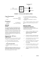
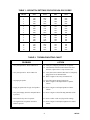
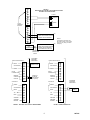
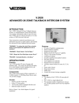
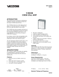
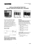
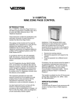
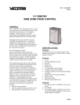
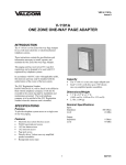
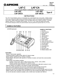
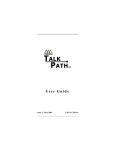
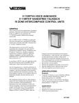
VSP-V-2901
Issue 6
V-2901
UNIVERSAL DOOR ANSWERING SYSTEM
INTRODUCTION
The V-2901 is a Universal Door Answering System
for use with any single line telephone, electronic or
1A2 key system, or PABX. These instructions
contain the specifications and information necessary
to install, operate, and maintain the Universal Door
Answering System.
SPECIFICATIONS
Purpose
Provides remote door answering from a telephone or
telephone system.
•
•
Applications
•
•
•
•
Electronic Key Systems
PABXs
1A2 Key Systems
Stand Alone Systems
•
•
Refer to Figure 1 for a block diagram of a typical
installation.
Capacity
•
•
Features
•
•
•
•
•
•
•
•
•
•
•
Ringback tone for speaker
Works with the Valcom V-1070A or V-1071
door plate speakers
AC line powered
Compatible with VPB-260 Battery Back-up
Line key access from Electronic or 1A2 key
systems
Loop trunk port access from PABX
Dedicated single line telephone access
Built in handsfree amplifier
RJ11 modular connector for Tip and Ring
connections
Power on LED
Provides contact for electric strike plate
Programmable door unlock codes (use with tone
dial telephones)
Input for manual door unlock (push-button)
Removable screw terminal blocks for all
connections
Built in (30 Hz) ringing generator (with on/off
switch)
The V-2901 is a single talkpath unit
Each V-2901 will drive up to 2 Valcom 45 Ohm
Talkback Speakers
Dimensions/Weight
•
•
8.6" H x 11.0" W x 2.3" D
(21.6cm H x 27.9cm W x 5.8cm D)
3 lbs. (1.36 kg)
Specifications
•
•
•
•
1
Input Impedance:
600 Ohms
Input Level:
-10 dBm Nominal
Output Impedance:
45 Ohms
Ring Supply:
90VAC, 30 Hz
Interrupted 1 sec. on 4 sec. off
947301
Door Plate Speaker
Assembly
V-2901
E-Key
C. O. Line Position
Speaker
UNIVERSAL
DOOR
ANSWER
UNIT
Pushbutton
FIGURE 1 - TYPICAL E-KEY INSTALLATION
Power Requirements
•
Voltage:
•
Power:
1) 1 V-2901 Universal Door Answering Unit
2) 1 Single Line Tone Dial Telephone dedicated
for door answer
3) 1 Valcom Door Plate Speaker (V-1070A or
V-1071))
115VAC
or 24VDC Battery Backup
25 watts
Environment
•
•
Temperature:
Humidity:
NOTE: A single line telephone cannot be connected
to both the V-2901 and an incoming central office
line.
0 to 50 Degrees C
0-85% non-precipitating
DESIGN
INSTALLATION
General
Connecting Arrangement
The V-2901 Remote Door Answering System when
used with the V-1070A Door Plate Speaker provides
voice paging with handsfree reply to a door. When
the push-button on the door plate speaker is pressed,
the phone system will ring. By answering the call, the
system user can converse with the person at the door.
If the door is equipped with an electric strike plate,
the system user may allow access by dialing a code or
pressing a button.
If a modular cord is used for Tip and Ring
connections, start at step ONE. For screw terminal
connections start at step TWO.
__1.
Connect one end of a modular cord to the
V-2901 RJ11 and the other end to the
appropriate line position of the phone
system. Go to step 4.
__2.
Connect Tip of the key system line position
(loop trunk) to Tip terminal of the V-2901.
When using the V-2901 with an electronic key system
or PABX, the following equipment will be required:
__3.
Connect Ring of the key system (loop trunk)
to the Ring terminal of the V-2901.
1) 1 V-2901 Universal Door Answering Unit
2) 1 C.O. Line Position (Electronic Key System
or
1 Loop Trunk Position (PABX)
1 400 type line card (1A2 key)
3) 1 Valcom V-1070A or V-1071 Door Plate
Speaker
__4.
Connect Tip and Ring of the V-1070A Door
Plate Speaker to V-2901 screw terminals
marked SPKR.
__5.
Connect Door Button terminals of V-1070A
to V-2901 screw terminals marked DPB.
__6.
Turn slide switch SW1 ON if the telephone
system is to ring when the door plate button
is pressed.
Electronic Key, 1A2 Key or
PABX Access
Dedicated Single Line Phone Access
When using the V-2901 with a single line telephone,
the following equipment will be required:
2
947301
__7.
__8.
Plug the V-2901 AC Line Cord into
appropriate 115VAC receptacle.
Battery Back-Up
A Valcom VPB-260 Battery Back-up may be added
to the system to provide power in case of power
failure. Figure 6 shows the appropriate connections.
The VPB-260 should be allowed to charge for
approximately 9 hours before operating the V-2901.
Adjust volume (See "Volume
Adjustments").
Remote Door Unlock with Tone Dial
Telephone
__1.
Refer to Table 1 for dip switch settings to
program single digit door unlock code.
__2.
Figure 3 shows the V-2901 contact
arrangement available for electric strike
plate operation.
OPERATION
General
When the door plate button is pressed, interrupted
ring voltage from the V-2901 is applied to a C.O. line
position of the telephone system and a ringback tone
is sent to the door plate speaker for the duration that
the call button is pressed. When the line is answered
the ringing is removed and the handsfree amplifier is
connected.
Before connecting an electric lock to the V-2901,
consult the manufacturers instructions for the proper
connecting arrangement.
If the door is equipped with an electric strike plate, a
preset number can be dialed from the tone dial
telephone, operating a relay for 2.2 seconds. The
relay provides make/break contacts that may be used
to operate the strike plate. A single pole push-button
switch connected to the V-2901 can also be used to
manually operate the door unlock relay.
Remote Door Unlock with
Push-button
__1.
Connect single pole push-button to V-2901
screw terminals marked Remote Control
Unlock.
The V-2901 provides make/break contacts that follow
the ringing cycle. These contacts can be used to
operate external signaling devices.
Remote Signaling
__1.
The V-2901 contains an auxiliary set of
make/break contacts. These contacts follow
the ringing cycle after the door plate
push-button has been pressed. They can be
used to operate a remote signaling device;
i.e., bell, buzzer, or light. Figure 4 shows a
typical connection using these contacts.
NOTE: Operation is the same when used with all
telephone systems.
TECHNICAL ASSISTANCE
Table 2 identifies symptoms of some possible
problems with solutions.
Volume Adjustments
There are three volume controls on the V-2901. Two
are used to adjust the page level to the door and the
handsfree reply. The third control adjusts the
ringback tone to the door plate speaker. See Figure 5
for location.
__1.
Phone to Speaker: Adjust this control to give
the desired listening level at the speakers.
__2.
Speaker to Phone: Adjust this control so the
reply from the speaker is clear.
IMPORTANT: This is the most critical
adjustment. Set the volume at the lowest
practical level. Setting this control too high
will increase background noise without
giving greater talkback volume.
__3.
Ringback Tone: Adjust this control to
produce the desired level of ringback tone at
the door plate speaker when the door plate
push-button is pressed.
Assistance in troubleshooting is available from the
factory. When calling, you should have a VOM and a
test set available and be calling from the job site.
Call (540) 427-3900 and ask for Technical Support,
or call (540) 427-6000 Valcom 24-hour Automated
Support or visit our website at
http://www.valcom.com.
Valcom equipment is not field repairable. Valcom,
Inc. maintains service facilities in Roanoke, VA.
Should repairs be necessary, attach a tag to the unit
clearly stating your company name, address, phone
number, contact person, and the nature of the
problem. Send the unit to:
Valcom, Inc.
Repair and Return Dept.
5614 Hollins Road
Roanoke, VA 24019-5056
3
947301
TABLE 1 - DIPSWITCH SETTINGS FOR DOOR UNLOCK CODES
DIGIT
SW1
SW2
SW3
SW4
1
2
3
4
ON
OFF
ON
OFF
OFF
ON
ON
OFF
OFF
OFF
OFF
ON
OFF
OFF
OFF
OFF
5
6
7
8
ON
OFF
ON
OFF
OFF
ON
ON
OFF
ON
ON
ON
OFF
OFF
OFF
OFF
ON
9
0
*
#
ON
OFF
ON
OFF
OFF
ON
ON
OFF
OFF
OFF
OFF
ON
ON
ON
ON
ON
A
B
C
D
ON
OFF
ON
OFF
OFF
ON
ON
OFF
ON
ON
ON
OFF
ON
ON
ON
OFF
TABLE 2: TROUBLESHOOTING CHART
PROBLEM
ACTION
1. No system operation - Power LED not lit.
1a. Verify AC voltage is present at the receptacle.
1b. Check the fuse located on the bottom of the unit.
If blown, replace with a 1 amp 250 VAC fuse.
2. No system operation - Power LED is lit.
2a. Verify that screw terminal connectors are completely
plugged into circuit board headers.
2b. Refer to Figure 2 and verify all connections.
3. No paging at speaker.
3a. Check door plate speaker connections.
3b. Refer to Figure 5 and adjust Phone to Speaker
volume.
4. Paging at speaker but no reply from speaker.
4a. Refer to Figure 5 and adjust Speaker to Phone
volume.
5. No system ringing when the doorplate button
is pressed.
5a. Refer to Figure 5 and check Ring ON/OFF switch.
6. Door unlock relay does not operate.
6a. Refer to Table 1 and verify dip switch settings.
7. No ringback tone to speaker when door
button is pressed.
7a. Refer to Figure 5 and adjust ringback tone volume
control.
4
947301
1
FIGURE 2
ELECTRONIC KEY SYSTEM, 1A2 LINE BUTTON ACCESS
OR PABX LOOP TRUNK ACCESS
2
3
V-1070A
4
5
DPB
Pushbutton
6
V-2901
TERMINAL
BLOCKS
7
Speaker
8
9
10
T
T
R
12
SPKR
13
R
11
E-KEY, 1A2 LINE POSITION OR
PABX LOOP TRUNK PORT OR
SINGLE LINE TELEPHONE
(1a)
14
RJ11
CONNECTOR
E-KEY, 1A2 LINE POSITION,
PABX LOOP TRUNK PORT OR
SINGLE LINE TELEPHONE
WITH MODULAR LINE JACK
(1b)
NOTE 1:
Tip and Ring connections can
be made by using cross connect
wire (1a) or by using a modular
cable (1b).
MODULAR
CONNECTING
CABLE
DOOR UNLOCK RELAY
MAKE
STATIONARY
CUSTOMER
PROVIDED
EQUIPMENT
DOOR UNLOCK RELAY
MAKE
ELECTRIC
STRIKE PLATE
STATIONARY
BREAK
BREAK
DOOR
PUSHBUTTON
DOOR
PUSHBUTTON
REMOTE
CONTROL
UNLOCK
Pushbutton
for Manual
Door Release
(if required)
REMOTE
CONTROL
UNLOCK
AUX RELAY
AUX RELAY
BREAK
BREAK
STATIONARY
STATIONARY
MAKE
MAKE
TIP
TIP
RING
RING
SPEAKER
SPEAKER
SPEAKER
RETURN
SPEAKER
RETURN
FIGURE 3 - ELECTRIC LOCK CONTACT ARRANGEMENT
CUSTOMER
PROVIDED
EQUIPMENT
RING
SUPPLY
FIGURE 4 - REMOTE SIGNALLING
5
947301
VALCOM LIMITED WARRANTY
Valcom, Inc. warrants its products to be free from defects in materials and workmanship under conditions of normal use and service
for a period of one year from the date of shipment. The obligation under this warranty shall be limited to the replacement, repair or
refund of any such defective device within the warranty period, provided that:
1.
2.
3.
4.
5.
inspection by Valcom, Inc. indicates the validity of the claim,
the defect is not the result of damage, misuse, or negligence after the original shipment.
the product has not been altered in any way or repaired by others and that factory sealed units are unopened (A service
charge plus parts and labor will be applied to units defaced or physically damaged),
freight charges for the return of products to Valcom are prepaid,
all units ‘out of warranty’ are subject to a service charge. The service charge will cover minor repairs (Major repairs will be
subject to additional charges for parts and labor).
This warranty is in lieu of and excludes all other warranties, expressed or implied, and in no event shall Valcom, Inc. be
liable for any anticipated profits, consequential damages, loss of time or other losses incurred by the buyer in connection
with the purchase, operation, or use of the product.
This warranty specifically excludes damage incurred in shipment. In the event a product is received in damaged condition, the
carrier should be notified immediately. Claims for such damage should be filed with the carrier involved in accordance with the
F.O.B. point.
Headquarters:
Valcom, Inc.
1111 Industry Avenue
Roanoke, VA 24013
Phone: (540) 437-3900
FAX: (540) 427-3517
Phone to
Speaker
SW4
SW3
SW2
SW1
Speaker
to Phone
Power
LED
Tone
In Canada
CMX Corporation
35 Van Kirk Drive #11 and 12
Brampton, Ontario L7A1A5
Phone: (905) 456-1072
FAX: (905) 456-2269
Program Switches
for Unlock Codes
V-2901
Handsfree Volume
Controls
.
.
.
.
.
Speaker Ringback
Tone Volume Control
VPB-260
SW1
Off
Bridged
Ring Switch
On
FIGURE 6
BATTERY BACK-UP
FIGURE 5
VOLUME CONTROL AND SWITCH LOCATIONS
6
947301