1
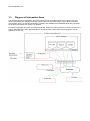
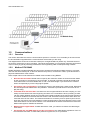
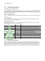
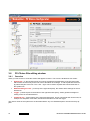
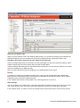
www.weidmueller.com
1.5
Communications
1.5.1
Overview
This section describes the various communications options in overview. For more detail you should consult
the documentation supplied with the communication devices that you are using.
The diagram above shows the most basic install (over a single RS485 bus) where only Transclinic devices
are used to monitor the PV Array operation. This simple setup allows you to maintain maximum performance
of the PV Array by quickly informing maintenance and engineering staff of underperforming modules.
1.5.2
Modbus RTU RS485
RS485 (defined by standard EIA485) has become the workhorse for allowing multiple devices to communicate over the same twisted pair. It does not describe the protocol, connectors or cable; it just describes the
physical characteristics of the network.
Some simple rules must be followed for reliable communications using RS485:
•
No more than 32 Loads: RS485 does not specify the maximum number of transceivers but allows
for the connection of a maximum of 32 ‘unit loads’. A unit load is typically a single device although
some transceivers are now available with ½ and ¼ unit load ratings. If you are unsure it is best to
stick to 32 especially if you are using higher speeds.
•
Use a daisy chain configuration: connecting a device to the twisted pair creates a stub. Minimising
the stub length avoids transmission line problems. Transclinics provide two bus connectors to simplify the wiring.
•
Terminate each end of the bus: to avoid errors due to signal reflections and line coupling, it is necessary to terminate the bus at the beginning and at the end. Terminate the bus by inserting a 120Ω
½W 5% resistor between wire B and A (positive and negative signals) at the last and first instrument.
A common mistake is to terminate the bus at each node, which will cause problems when there are
more than three of four nodes. The network termination is necessary even for point-to-point connections and connections over short distances. Improved performance may be achieved by using a ‘failsafe’ termination at one end of the network. You should follow the device manufacturer’s recommendations with regard to ‘failsafe’ terminations.
•
Maximum bus length 1200m: for data rates above 100k, you will have to restrict the cable length
even further.
•
Use twisted pair, 24 AWG cable for the bus connections: the characteristic impedance of the cable should be 100-120Ω. A 120Ω cable presents a lighter load, so it is preferred.