1
Solenoid Wrapping:
Step 1:
Measure and mark a 3.5" length on the pipe at the
selected locations for the solenoid coils.
The illustrated solenoid winding guidelines use a 3.5" length single layer
configuration (Teflon type E#18 awg wire).
Preferred Application
Step 2:
Tape this measured area with a thin material to allow the
wire to be installed side-by-side, it will provide electrical
insulation (a suitable tape is kapton).
Step 3:
Start the winding of the Teflon type E#18 awg stranded
wire in the measured area, starting at one side of the
work area and tape it in place. Be sure to measure the
distance needed, leaving enough wire to connect to the
solenoid connector when the coil is complete (Do Not
Twist or Cut Wire or the System WILL NOT Function ).
Step 4:
Wind the coil by slowly turning the pipe and guiding the
wire into the proper placement. As the winding proceeds, it is a good idea to glue the wire in place every
inch or so to insure that the coil is tight. ( be sure the
adhesive used does not react with the wire insulation).
Continue winding and guiding the wire into place until
the required 3.5" length is complete, secure the final
turn to be sure the coil remains tight. Then wrap the coil
with vinyl industrial tape to help maintain a tight coil and
protect the coil from loosening. At this point it is suggested that an impedance measurement test be made of the
coil to confirm that the coil is properly wound (suggested
test instrument EXTECH LCR meter number 380193 or
its equivalent).
IMPORTANT: When installing (wrapping) two solenoid
coils on one pipe, both coils must be wound in the same
clockwise or counter clockwise direction.Also it is necessary to connect the starting and returning wires of each
coil to the correct terminals as illustrated. Both coils are
connected to their own amplifier and these are synchronized.
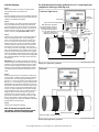
Solenoid
Connections
Alarm Relay
Current Source Universal Switching
Wire Leads Teflon Type E#18
awg. Approximately 150 feet of
wire needed for each Solenoid
Coil Wrap. Measure Distance
from Controller to Reaction
Chamber to determine if
additional wire is needed
Start Coil
Start Coil
Return Coil
Return Coil
10" (non-magnetic
Diameter Pipe
Six Inch (6")
Between
Solenoids
Solenoid Coil Length 3.5"
Overall Pipe length Approx 24" (dependent upon field situation)
Single pipe application guideline
Not to scale for reference only
Optional
Step 5:
When the solenoid coils on the reaction chamber winding is complete, a suitable covering should be prepared
to protect them The covering length should be (3.5" +
pipe ID X 2), and the OD covering of the pipe should be
pipe OD + 4". Cut the selected covering in half and then
reassembled using pipe clamps / adhesive over the coil .
Remember to drill a hole and pull the wire leads through
the hole and then connect to the suitable electrical connectors (for system integration with the TWT controller).
Center the selected cover over the solenoid coil.Place
wedges at each end of the solenoid coil, inside the
selected covering, to secure location. Again it is sug gested that an impedance measurement test be made
of the coil/ connector to confirm that they are properly
working (suggested test instrument EXTECH LCR meter
number 380193 or its equivalent).
Step 6:
Fill cavity with appropriate insulation.
Note: All selected covering used must be
non-magnetic, otherwise the performance of the
reaction chamber will be severely degraded.
Solenoid Coil Length 3.5"
Solenoid wrapping: as illustrated above
Double pipe application guideline
Email:[email protected] • [email protected] • Website:www.Triangularwave.com
Not to scale for reference only
3