1
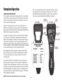
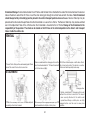
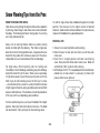
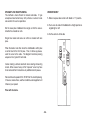
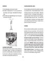
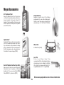
Snowplow Operation
Reset is accomplished by turning off the ignition switch or by turning
the power switch off momentarily and then back on. If the monitor
light is still illuminated after attempts to reset the switch have failed,
contact your nearest authorized Meyer Distributor for repairs.
HAND HELD CONTROLLER
The snow plow should only be in operation when the vehicle ignition
switch and the control switch are in the “ON” position. Care should
be taken to insure that the control switch is kept dry and free from
moisture during normal operation.
BACK/REAR
When the control switch is turned “On,” the on/off button will
illuminate. The individual touch pads operate the snow plow: (Up),
(Angle Left),(Left Extend), (Left Retract), (Angle Right), (Right Extend),
(Right Retract), (Scoop), (Vee) and (Down).
LEFT WING
CONTROL
SCOOP
MODE
Lowering of the snow plow an inch at a time is possible by tapping
the down arrow in short intervals. Holding down the down arrow
will activate a float light located next to the on/off button. This light
indicates the snow plow is now in the Lower/Float position. In this
position the snow plow will be able to follow the contour of the road
and the snow plow can also be angled to the left or right. Touching the
up arrow automatically cancels the Lower/Float position.
TOP/FRONT
FLOAT
MODE
ON/OFF
RIGHT WING
CONTROL
AUTO V MODE
UP/DOWN
LEFT/RIGHT
While angling left or right or raising the snow plow if the button is
pressed for more than six seconds the operation will be cancelled.
This feature eliminates unnecessary amp draw from the vehicle
charging system.
This handheld controller is self diagnosing. The systems monitor
light is located in the upper left corner next to the float light of the
controller. If the monitor light begins to flash the system is sensing a
malfunction. The number of flashes determines the exact location of
the potential problem. The diagnostic chart is conveniently located
on the back/rear of the handheld controller. See page 11-20 for more
detailed diagnostic information.
NOTE: The black wire with white stripe is the ground wire.
SYSTEMS
MONITOR
-5-