1
Connect Tech Xtreme/104-Plus, PCI-104 and PCI/104 Express Family User Manual
Xtreme/104 Plus Opto 4&8 Port
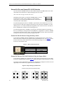
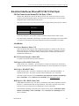
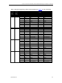
Table 3: 10 Pin R/A Port Header Pinouts on Opto Models
Pin No.
1
2
3
4
5
6
7
8
9
10
RS-232
NC
NC
RxD
RTS
TxD
CTS
NC
NC
isolated
gnd.
N/A
Direction
NC
NC
input
output
output
input
NC
NC
signal gnd.
N/A
Direction
RxD (+)
CTS (-)
RxD (-)
RTS (+)
TxD (+)
CTS (+)
TxD (-)
RTS (-)
isolated
gnd.
N/A
Direction
input
input
input
output
output
input
output
output
signal reference
N/A
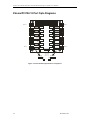
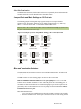
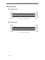
View facing 10 pin header
9
7
3
5
1
10 pin header
10
8
6
4
2
Printed circuit board
Cable header
Arrow
Red stripe = pin 1
Ribbon Cable
Note: The red stripe on the CAG104 cable indicates pin 1 on the
10 pin cable header connector.
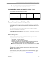
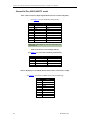
Table 4: DB-9 Male Fan-out Cable Pinouts
Pin #
DB-9
1
2
3
4
5
6
7
8
9
Signal
DCD
RxD
TxD
DTR
SG
DSR
RTS
CTS
RI
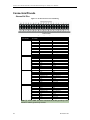
RS-232
Direction
Input
Input
RS-422/485
Direction
Input
Input
Output
Output
Signal Reference
Input
Output
Input
Output
Signal
RxD+
RxDOutput
TxD+
Output
TxDSignal Ground SR
Input
CTSOutput
RTS+
Input
CTS+
Input
RTS-
RS-423 [1]
Signal
Direction
RxD+
Input
RxDInput
TxDRef (TxD+)
Signal Reference
TxDOutput
GND
Ground [2]
CTSInput
RTSRef (RTS+)
Signal Reference
CTS+
Input
RTSOutput
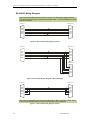
D
1
6
DB-9 Male
5
9
Notes:
[1] When CAG8104 cable assembly is attached.
[2] 47Ω to GND. Ground is connected to the DC ground by a 47Ω resistor to
reduce ground loop current
26
Revision 0.08