1
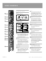
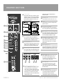
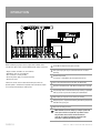
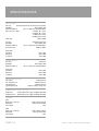
SM12 & SM16
STEREO MIC/LINE MIXING CONSOLES
OPERATION MANUAL
INTRODUCTION AND CONTENTS
The Australian Monitor Pro Series SM12 and SM16 stereo
console mixers are designed to be compact, ultra low noise and
feature packed.
INTRODUCTION
3
MONO CHANNELS
4
With a mixture of mono channels featuring balanced XLR or TRS inputs
and switchable 48V phantom power, and stereo channels all boasting
3 stage EQ and pre and post fader auxiliary sends, the SM series
mixers are as versatile as they are cost effective.
STEREO CHANNELS
5
MASTER SECTION
6
REAR PANEL
7
OPERATION
8
BLOCK DIAGRAM
9
SPECIFICATIONS
10
The SM Series mixers feature peak LED indication and low cut
filters on all mono channels, high quality 60mm faders and sealed
potentiometers, 19 inch rack mount kit and accurate 10 segment bar
graph meters for the stereo output buss.
The Australian Monitor Pro Series SM12 and SM16 give the audio
professional a sonically superior mixing console offering a feature set
and versatility usually found in mixing consoles many times their price.
AUS, EUR, USA
Copyright 17th Oct 2004
Rev A: 17th Oct 2004
This symbol is intended to alert the user to the presence
of uninsulated “dangerous voltage” within the product’s
enclosure that may be of sufficient magnitude to
constitute a risk of electric shock to persons.
This symbol is intended to alert the user to the presence
of important operation and maintenance (servicing)
instructions in the literature accompanying the appliance.
Caution:
SM12 & SM16 OPERATION MANUAL
To prevent electric shock do not use this (polarised) plug
with an extension cord, receptacle or other outlet unless
the blades can be fully inserted to prevent blade exposure.
To prevent electric shock, match wide blade of plug to
wide slot, fully insert.
PAGE 3
MONO CHANNELS
MIC/LINE INPUT SECTION
1
1 MIC
Balanced XLR input
2
This mid range EQ control adjusts mid
range frequencies and has a fixed 2
octave bandwidth at 2.5kHz. This control
will give up to 15dB of boost or cut. The
centre position will give a flat response.
7 LOW
3
4
6 MID
2 LINE
This low frequency shelf EQ control
adjusts bass frequencies and will give
up to 15dB of boost or cut at 80Hz. The
centre position will give a flat response.
6.35mm TRS input
AUXILIARY SECTION
8 PRE
5
Aux 1 is a mono split of the channel input
signal and is post EQ but pre the
channel fader.
6
9 POST
7
Aux 2 is a mono split of the channel input
signal and is post EQ and post
channel fader.
8
9
10
11
12
13
3 LOW CUT FILTER SWITCH
This switch will roll off frequencies below
75Hz at an 18dB per octave slope. This
can be used to eliminate rumble caused
by sensitive lectern mics etc.
4 GAIN
This is the initial gain control for each
input and should be set to optimise each
inputs level while still leaving headroom
so the input signal does not reach clipping
level. This gain stage has a range from
+10dB to +60dB.
EQ SECTION
5 HIGH
This is a shelf EQ filter that adjusts treble
frequency levels and will give up to 15dB
of boost or cut at 12kHz. The centre
position will give a flat response.
PAGE 4
10 PAN
The channel pan control is used to position the channel signal in the stereo field.
11 PFL
The Pre Fader Listen (PFL) switch is used
to monitor the input signal before the
channel fader. This can be switched to
either the headphone/local monitor output
or the master left/right outputs
(see master section)
12 PEAK LED
This red LED illuminates when the
channel is going into overload (clip)
13 LEVEL
This channel output fader adjusts the
level of the channels signal before it
is sent to the master output buss.
SM12 & SM16 OPERATION MANUAL
STEREO CHANNELS
LINE INPUT SECTION
14 LINE L/R
These 6.35mm TRS jacks will accept
either balanced or unbalanced line
level signals. For mono operation use
left input only.
AUXILIARY SECTION
18 PRE
Aux 1 is a mono split of the channel
input signal and is post EQ but pre the
channel fader.
14
19 POST
Aux 2 is a mono split of the channel
input signal and is post EQ and post
channel fader.
20 PAN
EQ SECTION
15 HIGH
This is a stereo shelf EQ filter that adjusts
treble frequency levels and will give up to
15dB of boost or cut at 12kHz. The centre
position will give a flat response.
16 MID
This stereo mid range EQ control adjusts
mid range frequencies and has a fixed
2 octave bandwidth at 2.5kHz. This
control will give up to 15dB of boost or
cut. The centre position will give a flat
response.
17 LOW
This low frequency stereo shelf EQ
control adjusts bass frequencies and will
give up to 15dB of boost or cut at 80Hz.
The centre position will give a flat
response.
SM12 & SM16 OPERATION MANUAL
The channel pan control is used to
position the channel signal in the stereo
field. This differs from the mono channels
as this pan control will determine the level
of either the Left or Right buss that is sent
to the master mix. For example if the pan
control is turned fully clockwise, only the
Right signal path will be sent to the
master mix. If the Left input only is
connected (a mono signal) the pan control
will work as per the mono channels.
15
16
17
18
19
20
21 PEAK LED
This red LED illuminates when the
channel is going into overload (clip)
21
22
22 PFL
The Pre Fader Listen (PFL) switch is used
to monitor the input signal before the
channel fader. This can be switched to
either the headphone/local monitor
output or the master left/right outputs
(see master section)
23 LEVEL
This Channel output fader adjusts the
level of the channels signal before it
is sent to the Master output buss.
23
PAGE 5
MASTER SECTION
24 LOCAL MON
These TRS 6.35mm jacks provide a stereo
output that can be sent to a local monitor
amp and speakers for control room or bio
box monitoring of either the PFL buss or
the master output buss.
output. This level is independent of
the Master Mix.
28 POWER LED
This LED indicates that the mixer is "on"
29 +48V
This LED indicates that 48 volt phantom
power is active.
24
30 L/R OUTPUT METER
The Master Output level is displayed on
these 10 segment Bar Graph peak meters.
31 MASTER/PFL TO LOCAL MONITOR
25
26
27
28
29
30
31
32
This switch determines whether the Master
mix signal or the PFL signal will be sent to
the Local Monitor/Headphone output.
25 HEADPHONES
This a monitor output for headphones.
This outputs signal will follow whatever is
assigned to the Local Monitor output.
26 AUX RETURN 1/2
These controls adjust the level of the stereo
auxiliary returns. Both Aux Return 1 & 2 are
permanently assigned to the Master Mix.
27 HEADPHONE/LOCAL MONITOR LEVEL
32 TAPE/REC TO MASTER
This switch determines whether a tape or
other stereo source connected to the
Tape In RCA connectors is sent to the
Master Mix.
33 MASTER OUTPUT
This fader controls the master output level of
both the Left and Right busses to the master
XLR and TRS outputs of the mixing console.
This control adjusts the output level of the
Local Monitor outputs and the Headphone
35 AUX SEND 1/2
These unbalanced 6.35mm jacks can
be used to send the output of each
channels Aux sends to effects devices
such as reverb or delay units.
33
34
35
36 37
34 STEREO AUX RETURNS 1/2
These 2 additional stereo inputs can be
used for the return of stereo effects
units such as reverb or delay units and
are permanently assigned to the Master
Mix. These can also be used as extra
line level inputs and can be mono if only
the left input is used.
PAGE 6
36 L/R TAPE IN
These stereo RCA connectors allow
connection of a tape deck, CD/DVD
player etc to the mixer and are routed to
the Master Mix.
37 L/R RECORD OUT
These stereo RCA connectors allow for
a tape deck or digital recorder to be
connected to mixing console for
recording the output of the Master Mix.
SM12 & SM16 OPERATION MANUAL
REAR PANEL
38 INSERTS 1-4 (1-8 ON THE SM16)
An insert point is provided for each
Mono Channel on the SM12 and SM16
mixing consoles. These insert points are
a split of the channels input signal
which is post input gain and Low cut
filter with the return path pre EQ. These
inserts are 6.35mm TRS sockets with Tip
being send and ring being return.
39
40
41
39 POWER
This switch turns mains power "on" to
the mixer
40 AC POWER
This is the connection for the supplied
AC power supply.
Please use supplied mains
power supply only. Always
connect the power supply to the
mixer before connecting to the
mains supply.
SM12 & SM16 OPERATION MANUAL
Tip = Send, Ring = Return
42
41 PHANTOM
This switch turns 48 volt phantom power
"on" to all mono channels. Phantom
power is required for Electret or
Condenser style microphones
42 STEREO OUT
Both balanced XLR and 6.35mm TRS
jacks are included and provide Stereo
mix output at the level set by the Master
output fader. Both sets of outputs can
be used simultaneously.
PAGE 7
OPERATION
Before connecting any input sources to your SM12 or SM16 stereo
console mixer, please make sure the following initial settings are correct.
• All gain controls and faders are set to minimum
• All Auxiliary sends are set to minimum
• EQ is set flat (i.e. in centre position)
• Ensure the power supply is correctly connected
• No PFL’s are active
Connect mic or line source to desired channel inputs (make sure
phantom power is switched on if required) and ensure Master Outputs
are correctly connected to your audio system.
1 Set the Master Output to unity gain (set to "0")
2 Turn up the input gain for your selected channel to 12 O’clock
(half way)
3 Generate input signal
(i.e. voice for a microphone, play background source etc)
4 Ensure the selected channels Peak LED is not illuminating
5 Raise the selected channels fader till the desired level is achieved
6 The L/R Output meter should be continuously metering at up to 0dB
with any transient signals not exceeding the +6dB indicator.
7 Adjust input gain stage to ensure correct gain settings
8 EQ input signals as required remembering that boosting frequencies
will add to the signals gain.
9 Repeat for remaining channels
☛
PAGE 8
NOTE: A full discussion of setting up a complex system with
correct gain structure is beyond the scope of this manual.
The procedure above assumes that the installer has
correctly set up external equipment connected to this
mixer prior to initiating the setup procedure.
SM12 & SM16 OPERATION MANUAL
BLOCK DIAGRAM
SM12 & SM16 OPERATION MANUAL
PAGE 9
SPECIFICATIONS
MONO INPUTS
Mic Input
Electronically balanced, discrete input configuration
Bandwidth
10Hz to 60kHz ± 3dB
Distortion (THD & N)
0.01% at +4dBu, 1kHz, Bandwidth 80kHz
Mic E.I.N. (22Hz - 22kHz)
-129.5dBu, 150Ω source
-117.3dBqp, 150Ω source
-132.0dBu, input shorted
-122.0dBqp, input shorted
GAIN range
+10dB to +60dB
Line Input
Bandwidth
Distortion (THD & N)
Line Level Range
Equalisation
Hi Shelving
Mid Range
Lo Shelving
STEREO INPUTS
Line Input
Bandwidth
Distortion (THD & N)
Equalisation
Hi Shelving
Mid Range
Lo Shelving
MASTER MIX SECTION
Max. Output
Aux. Send Max. Out
Control Room Out
Signal-to-Noise Ratio
Electronically balanced
10Hz to 60kHz ±3dB
0.01% at +4dBu, 1kHz, Bandwidth 80kHz
+10dBu to -40dBu
12kHz ±15dB
2.5kHz ±15dB
80Hz ±15dB
Unbalanced
10Hz to 55kHz ±3dB
0.01% at +4dBu, 1kHz, Bandwidth 80kHz
12kHz ±15dB
2.5kHz ±15dB
80Hz ±15dB
+22dBu Balanced
+22dBu Unbalanced
+22dBu Unbalanced
112dB, all channels at Unity Gain
POWER SUPPLY (mains voltages)
USA/Canada
-115VAC, 60Hz, power supply unit MXUL2 (included)
Europe/Australia -230VAC, 50Hz, power supply unit MXUK2 (included)
PHYSICAL
SM12
Dimensions (H x W x D)
Net Weight
Gross Weight
70mm x 293mm x 344mm
3.6kg (PSU not included)
5.8kg
SM16
Dimensions (H x W x D)
Net Weight
Gross Weight
70mm x 399mm x 344mm
5kg (PSU not included)
8.0kg
PAGE 10
SM12 & SM16 OPERATION MANUAL
AUSTRALIA AND NEW ZEALAND
www.australianmonitor.com.au
SYDNEY
MELBOURNE
BRISBANE
ADELAIDE
PERTH
AUCKLAND
(NSW & ACT SALES)
(VIC & TAS SALES)
(QLD SALES)
(SA & NT SALES)
(WA SALES)
(NZ SALES)
149 Beaconsfield
Street Silverwater
NSW 2128
Private Bag 149
Silverwater NSW 1811
Phone: (02) 9647 1411
Fax: (02) 9648 3698
Email:
[email protected]
22/277 Middleborough
Road Box Hill
VIC 3128
PO Box 151 Blackburn
South VIC 3130
Phone: (03) 9890 7477
Fax: (03) 9890 7977
Email:
[email protected]
42 Commercial Road
Fortitude Valley
QLD 4006
PO Box 871 Fortitude
Valley QLD 4006
Phone: (07) 3852 1312
Fax: (07) 3252 1237
Email:
[email protected]
31 Walsh Street
Thebarton
SA 5031
PO Box 157
Hindmarsh SA 5007
Phone: (08) 8352 4444
Fax: (08) 8352 4488
Email:
[email protected]
299 Fitzgerald Street
West Perth WA 6005
PO Box 404
North Perth
WA 6906
Phone: (08) 9228 4222
Fax: (08) 9228 4233
Email:
[email protected]
Unit B, 11 Piermark
Drive Albany 1331
New Zealand
PO Box 512
Albany 1331
Phone: (09) 415 9426
Fax: (09) 415 9864
Email:
[email protected]
EUROPE/ASIA/MIDDLE EAST
USA/SOUTH AMERICA
www.australianmonitor.com.au
www.australianmonitor.com
INTERNATIONAL SALES
SENNHEISER ELECTRONIC CORPORATION
149 Beaconsfield Street Silverwater NSW 2128 Australia
Private Bag 149 Silverwater NSW 1811
Phone: 61 2 9647 1411
Fax: 61 2 9648 3698
Email: [email protected]
1 Enterprise Drive
Old Lyme CT 06371 USA
Phone: 1 860 434 9190
Fax: 1 860 434 1759
Email: [email protected]