1
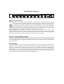
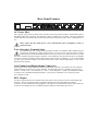
TX8202
8 Channel Stereo Mixer
with Direct Outputs
Operating Manual
TX8202, 8 Channel Stereo Mixer
Product Description
The TX8202 is a single rack height, 8 channel stereo mixer with direct outputs suitable for desk or 19” rack
mounting. The TX8202 has 4 balanced mic or line inputs and 4 stereo auxiliary inputs. Each input channel
has individual bass, treble and pan controls. The first 4 channels also feature a line level direct output which
can be used to feed additional amplifiers, mixers or recording devices. An internal dip switch allows the
first 4 inputs to be routed to either the direct output, the master outputs or both. The TX8202 also features
in-built VOX muting and an optional 4 tone generator with Alert, Evacuate, Pre-Announce, Bell tones and
optional remote VCA for the Master Volume.
Front Panel Features
Input Level Controls
Mic/Line Gain: The first 4 inputs are labeled Mic/Line 1 to Mic/Line 4 and should be adjusted to provide
the required mix level for each individual channel. Start with the controls set to Level 0 and turn
the controls clockwise until the desired mix level for each channel is reached. Each of the 4 inputs
is equipped with an mic/line dip switch which is located inside the unit (see Internal Adjustments).
Please ensure that this switch is in the correct position for the type of input (mic or line) that you are
connecting to each channel. The input sensitivity when in the mic level position is 1mV (for 1 Volt output).
The input sensitivity when in the line level position is 330mV (for a 1 Volt output)
Stereo Line Gain: The 4 auxiliary input channels are labeled Stereo Line 5 to Stereo Line 8. These
controls should be adjusted to provide the required mix level for each individual auxiliary channel. Start
with the controls set to Level 0 and turn the controls clockwise until the desired mix level for each channel
is reached. The sensitivity of auxiliary inputs 5 to 8 is 180 mV (for a 1 volt output).
Master Left and Right Output
The master Left and Right controls should be adjusted to set the overall mixer level for each output channel
based on the individual levels already set via the input channel gain controls. Start with the output controls
set at approximately the Level 5 position and adjust clockwise for more output level or counter-clockwise
for less output level.
Pan Control
Each input channel has a recessed (screwdriver adjustable) pan control. The pan control determines what
proportion of each input channel will be sent to either of the Left or Right output channels. Setting the pan
control in the centre position will send equal signal levels to both the Left and Right master outputs.
Turning the pan control in a clockwise direction will send progressively more signal to the Right output
channel and less to the Left output channel. Turning the pan control in a counter-clockwise direction will
send progressively more signal to the Left output channel and less to the Right output channel. The pan
control also allows the TX8202 to be used in dual zone applications.
Bass Control
Each input channel has a recessed (screwdriver adjustable) bass tonal adjustment control labeled “Bass”.
Setting this control in the centre position will give a flat bass response. Adjusting the bass control in a
clockwise direction will provide up to 12 dB of bass boost @ 100 Hz. Adjusting the bass control in a
counter-clockwise direction will provide up to 12 dB of bass cut @ 100 Hz.
Treble Control
Each input channel has a recessed (screwdriver adjustable) treble tonal adjustment control labeled
“Treble”. Setting this control in the centre position will give a flat treble response. Adjusting the treble
control in a clockwise direction will provide up to 10 dB of treble boost @ 10KHz. Adjusting the treble
control in a counter-clockwise direction will provide up to 10 dB of treble cut @ 10KHz.
LED Display VU Meter
An 8 segment LED VU meter is provided for each of the master Left and Right outputs. The VU meters
indicate output signal level from -21 to +3 dB. For normal operation the LED’s should rarely oscillate in
the red zone. If the LED’s in the red zone are lit continually, then the output level controls should be turned
counter-clockwise to reduce the output level. Too much output level can cause signal distortion and a
mismatch with the device that the mixer is driving. The far left blue LED on each the VU meters is for
indication that AC power is switched ON to the unit only.
Headphone Output Socket
A 1/4” TRS stereo socket is provided for the connection of monitor headphones. The output level to the
headphones is a nominal 3 volts @ 600 ohms and is connected before the master output level controls.
Adjusting the master output level controls will not affect the headphone output level.
Power Switch & “On” LED
The black rocker switch on the right hand side of the front panel is used to switch the mixer on and off. The
‘up’ position is on. When the amplifier is connected to an appropriate AC power source and is switched on,
the blue on LED’s (located on the left side of both LED displays) will illuminate.
Rear Panel Features
AC Power Inlet
The 3 pin IEC power inlet is located on the left side of the rear panel and accepts a standard mains power
lead fitted with an IEC connector. The operating voltage is 230/240 VAC @ 50 Hz. The inlet is equipped
with an inbuilt AC fuse holder fitted with a 63mA slow blow fuse plus one spare. Power consumption is 15
VA.
Please ensure that the mains power cord is disconnected before attempting to check or
replace this fuse.
Tone Generator Terminal Strip
The TX8202 allows for an optional tone generator module to be installed. When installed the four
tones may be activated via a simple contact closure. To activate a tone, just short out the common
terminal with the terminal labeled with the tone that you want to use. When activated, any of the
four tones will mute all inputs except for channels 1 and 2. While the tone generator function is (as default)
set up to be present on both the master outputs and the direct outputs (of channels 1-6), it can be disabled
for all or any of the direct outputs via an internal dip switch (see the ‘Internal Adjustments’ section of this
manual for more details).
Left Channel and Right Output Connectors
The rear panel of the TX8202 includes two male XLR output connectors. The output is an active balanced
isolated output for connection to a power amplifier. The maximum output is 1.5V RMS. Pin connections
are Pin 1 = Earth. Pin 2 = Active Positive (+). Pin 3 = Active Negative (-). Note: If an unbalanced output
is required, use a 600 Ohm matching transformer or use only Pin 2 and Earth. Do not short any of the
active outputs to earth.
REC Output
Two RCA output connectors are included on the rear panel. These provide a line level record output from
the mixer. The record output provides a maximum of 500mV into 10K ohms making it ideal for
connection to most standard recording equipment. This output is sourced before the master gain control and
as such the record output level is not influenced by the operation of the master gain control.
Dual RCA Stereo Line Inputs
The top connectors are for the Left channel auxiliary inputs while the bottom connectors are for the Right
channel auxiliary inputs. Reading from Left to Right across the rear panel, the connections are for auxiliary
inputs 8, 7, 6 and 5.
XLR Microphone/Line Inputs
Each XLR input is switchable to be either balanced mic or line (via an internal dip switch, the
location and setting of which is explained in the ‘Internal Adjustments’ section of this manual).
When set to mic level, the mic input sensitivity is 1mV ( for a 1 Volt output). When set to line
level, the input sensitivity is 330 mV (for a 1 Volt output). Pin connections are: pin #1-earth; pin #2-active
(high, +); pin #3-active (low, -). Phantom power of +15 volts is available on all 4 XLR inputs. An internal
phantom power ON-OFF switch is provided for each channel. The default setting is ON (See the ‘Internal
Adjustments’ section of this manual for more details).
Direct Outputs
A unique feature of the TX8202 is the individual direct output available for each of the first 4
channels. The direct outputs are accessed via balanced TRS 1/4” sockets for each channel. The
level of each output is 1 Volt (nominal). Internal jumpers (JP1) allow signal from any of the first
six channels to be disconnected from the main left/right outputs (See the ‘Internal Adjustments’ section of
this manual for more information). The direct outputs are adjustable to be pre or post the channel level
control. Factory default setting is post fader.
Vox Muting
Priority muting is provided for channels 1 and 2. Both channels have equal priority and will mute
channels 3-8 when signal is present. The muting function may be disabled by moving the jumper
labeled JP2 (located on the pcb behind the channel 8 volume control). ON and OFF positions are
clearly indicated on the pcb beside the jumper. The unit ships from the factory with muting enabled (JP2 OFF) – that’s right, OFF; it is a muting disable function, not a muting enable function. When channels 1
and 2 are disconnected from the main left/right outputs, the muting function is automatically disabled.
Internal Adjustments
Note: The following adjustments involve access to the inside of the TX8202 and should
only be attempted by a qualified technician. Always turn off the AC power and remove
the AC power cord before accessing the inside of the TX8202.
Tone Generator
There is a plug in option for a separate tone generator module.
VCA Control
There is a plug in option for a separate VCA module. You will need a module for each of the left and right
channels.
Master Left/Right Direct Out Assignment: A jumper labeled JP1 is provided for each of the first 4
channels. The jumpers are located near the front of the unit. When in the ON position, signal from that
channel is fed to both the master outputs and the direct outputs. When the switch is in the OFF position,
signal from that channel is fed to the direct line level output only. The pre or post assignment is set via a
jumper situated mid way towards the right on each channel labeled “Pre Post”. This is used to make the
Direct Outputs either pre or post channel fader volume. Set to the rear the Direct Output is post fader (i.e.
the channel fader volume affects the Direct Output). Set to the forward position the Direct Output is pre
fader.
Mic/Line Switch for Channels 1-4: A four position dip switch is located on the main board behind each
input. To set a channel for microphone level, set switches 1 and 2 (MIC) to the ON position. To set a
channel for line level, set switches 1 and 2 to the OFF position. The unit ships from the factory set to mic
level.
Tone Generator to Direct Output Defeat Switch: Signal from the tone generator can be removed from
each direct output via switch # 4 (TG) on the internal dip switch per channel. When in the ON position, the
tones (when activated) are fed to the corresponding direct output as well as the master Left/Right outputs.
When the switch #4 is set to the OFF position, the tones are only present at the Master Left/Right outputs.
Phantom Power Defeat: Each of the XLR inputs has access to +15v DC phantom power. Phantom power
is selected via switch # 3 (PP) on the internal dip switches mentioned above. When switch # 3 is in the ON
position, +15v phantom power is available on the XLR input. Care should be taken to disable phantom
power before connecting any unbalanced or line source. The factory default position is with phantom power
set to the ON position.
Vox Muting Defeat: The muting function can be disabled by moving the jumper labeled JP2 (located
behind channel 8 volume control). In the ON position muting is disabled, in the OFF position muting is
enabled (go figure!). The unit ships from the factory with muting enabled, ie the jumper is set to the OFF
position. When channels 1 and 2 are removed from the main left/right output, the muting function is
automatically disabled.
Addendum to TX8202 Manual
Issue Release Date: 11th January 2007
Correction/Change: Vox muting enable/disable header location.
This addendum to the TX8202 manual corrects the text discussing the Priority mute function. The following text has changed
on page 5 Features and Page 6 Internal Adjustments
Vox Muting
Priority muting is provided for channels 1 and 2. Both channels have equal priority and will mute channels 3-8 when signal is
present. The muting function may be disabled by moving the jumper labeled JP3 (See the ‘Internal Adjustments’ section of
this manual for more information). The unit ships from the factory with muting enabled.
When channels 1 and 2 are disconnected from the main left/right outputs, the muting function is automatically disabled.
Internal Adjustments
Vox Muting Defeat: The muting function may be disabled by moving the jumper labeled JP3 (located on the pcb
close to Right output). The OFF position is clearly indicated on the pcb beside the jumper (JP3 towards the rear panel).
The unit ships from the factory with muting enabled.
VOXJP3
OFF
When channels 1 and 2 are disconnected from the main left/right outputs, the muting function is automatically disabled.
Addendum to TX8202 Manual
Issue Release Date:
Correction/Change: Vox muting enable/disable header
location.
This addendum to the TX8202 manual corrects the text
discussing the Priority mute function. The following text
has changed on page 5 Features and Page 6 Internal
Adjustments.
Vox Muting
Priority muting is provided for channels 1 and 2. Both
channels have equal priority and will mute channels 3-8
when signal is present. The muting function may be
disabled by moving the jumper labeled JP3 (See the
‘Internal Adjustments’ section of this manual for more
information). The unit ships from the factory with muting
enabled.
When channels 1 and 2 are disconnected from the main
left/right outputs, the muting function is automatically
disabled.
Internal Adjustments
Vox Muting Defeat: The muting function may be disabled
by moving the jumper labeled JP3 (located on the pcb
close to Right output). The OFF position is clearly indicated
on the pcb beside the jumper (JP3 towards the rear panel).
The unit ships from the factory with muting enabled.
When channels 1 and 2 are disconnected from the main
left/right outputs, the muting function is automatically
disabled.
OFF
VOXJP3
Important Safety Information
1. Save the carton and packing material even if the equipment has arrived in good condition. Should you ever need to ship the
unit, use only the original factory packing.
2. Read all documentation before operating your equipment. Retain all documentation for future reference.
3. Follow all instructions printed on unit chassis for proper operation.
4. Do not spill water or other liquids into or on the unit, or operate the unit while standing in liquid.
5. Make sure power outlets conform to the power requirements listed on the back of the unit.
6. Do not use the unit if the electrical power cord is frayed or broken. The power supply cords should be routed so that they are
not likely to be walked on or pinched by items placed upon or against them, paying particular attention to cords and plugs,
convenience receptacles, and the point where they exit from the appliance.
7. Always operate the unit with the AC ground wire connected to the electrical system ground. Precautions should be taken so that
the means of grounding of a piece of equipment is not defeated.
8. Mains voltage must be correct and the same as that printed on the rear of the unit. Damage caused by connection to improper
AC voltage is not covered by any warranty.
9. Have gain controls on amplifiers turned down during power-up to prevent speaker damage if there are high signal levels at the
inputs.
10. Power down & disconnect units from mains voltage before making connections.
11. Never hold a power switch in the “ON” position if it won’t stay there itself!
12. Do not use the unit near stoves, heat registers, radiators, or other heat producing devices.
13. Do not block fan intake or exhaust ports. Do not operate equipment on a surface or in an environment which may impede the
normal flow of air around the unit, such as a bed, rug, weathersheet, carpet, or completely enclosed rack. If the unit is used in an
extremely dusty or smoky environment, the unit should be periodically “blown free” of foreign matter.
14. Do not remove the cover. Removing the cover will expose you to potentially dangerous voltages. There are no user serviceable
parts inside.
15. Do not drive the inputs with a signal level greater than that required to drive equipment to full output.
16. Do not connect the inputs / outputs of amplifiers or consoles to any other voltage source, such as a battery, mains source, or
power supply, regardless of whether the amplifier or console is turned on or off.
17. Do not run the output of any amplifier channel back into another channel’s input. Do not parallel- or series-connect an
amplifier output with any other amplifier output.
Australian Monitor Inc is not responsible for damage to loudspeakers for any reason.
18. Do not ground any red (“hot”) terminal. Never connect a “hot” (red) output to ground or to another “hot” (red) output!
19. Non-use periods. The power cord of equipment should be unplugged from the outlet when left unused for a long period of time.
20. Service Information Equipment should be serviced by qualified service personnel when:
A. The power supply cord or the plug has been damaged.
B. Objects have fallen, or liquid has been spilled into the equipment
C. The equipment has been exposed to rain
D. The equipment does not appear to operate normally, or exhibits a marked change in performance
E. The equipment has been dropped, or the enclosure damaged.
Engineered in Sydney, Australia
AUSTRALIA AND NEW ZEALAND
www.australianmonitor.com.au
EUROPE / ASIA / MIDDLE EAST
www.australianmonitor.com.au
SYDNEY (NSW & ACT SALES)
INTERNATIONAL SALES
149 Beaconsfi eld Street Silverwater NSW 2128
Private Bag 149 Silverwater NSW 1811
Phone: (02) 9647 1411
Fax: (02) 9648 3698
Email: [email protected]
Private Bag 149, Silverwater NSW 1811
149 Beaconsfield Street, Silverwater NSW 2128
Australia
Ph: 61-2- 9647 1411
Fax: 61-2-9748 2537
E-mail: [email protected]
MELBOURNE (VIC & TAS SALES)
22/277 Middleborough Road Box Hill VIC 3128
PO Box 151 Blackburn South VIC 3130
Phone: (03) 9890 7477
Fax: (03) 9890 7977
Email: [email protected]
BRISBANE (QLD SALES)
42 Commercial Road Fortitude Valley QLD
4006
PO Box 871 Fortitude Valley QLD 4006
Phone: (07) 3852 1312
Fax: (07) 3252 1237
Email: [email protected]
ADELAIDE (SA & NT SALES)
31 Walsh Street Thebarton SA 5031
PO Box 157 Hindmarsh SA 5007
Phone: (08) 8352 4444
Fax: (08) 8352 4488
Email: [email protected]
PERTH (WA SALES)
299 Fitzgerald Street West Perth WA 6005
PO Box 404 North Perth WA 6906
Phone: (08) 9228 4222
Fax: (08) 9228 4233
Email: [email protected]
AUCKLAND (NZ SALES)
Unit B, 11 Piermark Drive Albany 1331 New
Zealand
PO Box 512 Albany 1331
Phone: (09) 415 9426
Fax: (09) 415 9864
Email: [email protected]
USA / SOUTH AMERICA
www.australianmonitor.com
SENNHEISER ELECTRONIC
CORPORATION
1 Enterprise Drive Old Lyme CT 06371 USA
Phone: 1 860 434 9190
Fax: 1 860 434 1759
Email: [email protected]