1
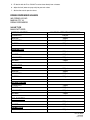
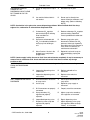
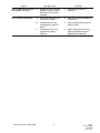
www.cornelius.com
Telephone (800) 238-3600
INSTALLATION INSTRUCTION
THIS INSTALLATION INSTRUCTION APPLIES TO ALL MODELS OF
DROP-IN AND FREE-STANDING ICE COOLED DISPENSERS.
UNPACKING AND INSPECTION
The unit was thoroughly inspected before leaving the factory and the carrier has accepted and signed for it. Any
damage or irregularities should be noted at the time of delivery and immediately reported to the delivery carrier.
Request a written inspection report from Claims Inspector to substantiate any necessary claim.
Claims must be filed with the delivery carrier.
SELECTING A LOCATION
CAUTION: Water pipe connections and fixtures directly connected to a potable water
supply shall be sized, installed and maintained according to federal, state and local laws.
The dispenser must be located near a permanent drain to route and connect unit ice bin and drip tray drain
hoses. All drains and connections to such drains must meet local plumbing codes.
Units with electrically operated valves must be located near a properly grounded electrical outlet. Circuit should
be fused and no other electrical appliance should be connected to the circuit. ALL ELECTRICAL WIRING
MUST CONFORM TO NATIONAL AND LOCAL ELECTRICAL CODES.
INSTALLING THE DISPENSER
Drop-In Dispenser
1. Use the Template supplied to mark the location of the hole to be cut into the counter top. Cut the hole as
marked and remove the material.
2. Apply the double stick tape (if supplied with the loose shipped parts).
Note: To comply with the National Sanitation Foundation (NSF) requirements, the unit must be sealed
to the counter top.
3. Liberally apply a sealant, such as Dow Corning RTV 731 or equivalent, to the unit flange bottom surface.
4. Lower the unit into position to complete the seal of the rim to the counter top. Apply additional sealant
around the rim to ensure a complete seal.
Note: Do not move the unit after positioning or the seal will be broken.
EIMI Cornelius Inc; 1994–2003
1
10/4/94
Revised 10/8/03
166239001
Rev. Level1
5. Remove any excess sealant.
Note: For non-electrical valves, skip the next step.
6. Mount the Transformer power supply under the counter, in a position to allow access to the electrical outlet
and to allow the 24V power cord to reach the dispenser.
7. Install the drain hose to the ice bin drain fitting and route the drain hose to a permanent drain.
Free-Standing Dispenser
1. Install the 6“ legs to the dispenser cabinet if they are to be used.
2. Place the dispenser in the location selected. Be sure the dispenser is level. This is important to ensure that
the bin drains properly.
3. Mount the Transformer power supply in a convenient location to allow access to the electrical outlet and to
allow the 24V power cord to reach the dispenser.
4. Install the drain hose to the ice bin drain fitting and route the drain hose to a permanent drain.
SANITIZING PRODUCT COLD PLATE TUBING
Preparing the Cleaning Solution: Using a clean tank (tank system) or a five-gallon container (bag-in-box system), prepare a full tank or container of liquid dishwasher detergent by using 70° F (21° C) to 100° F (38° C)
potable water and 0.5 oz. (15 ml) of liquid dishwasher detergent (such as Joy, Ivory, etc.) to one gallon of potable water. Shake detergent solution to thoroughly mix the solution.
Preparing the Sanitizing Solution: Using a clean tank (tanks system) or a five-gallon container (bag-in-box
system), prepare sanitizing solution using 70° F (21° C) to100° F (38° C) potable water and 0.5 oz. (15 ml) of
household liquid bleach such as non-scented Hi-Lex or Chlorox that contains a 5.25 % sodium hypochlorite concentration to one gallon of potable water.This mixture must not exceed 200 PPM of chlorine. Shake sanitizing
solution to thoroughly mix.
STEP 1. WASH PRODUCT/SYRUP SYSTEMS
1. Using a clean tank (tank system) or a five-gallon container (bag-in-box system), prepare a full tank or container of liquid dishwasher detergent by using 70° F (21° C) to 100° F (38° C) potable water and 0.5 oz. (15
ml) of liquid dishwasher detergent (such as Joy, Ivory, etc.) to one gallon of potable water. Shake detergent
solution to thoroughly mix the solution.
Tank Systems.
A.
Observe and note CO2 pressure setting on the tanks CO2 regulator, then re-adjust CO2 regulator to 60
to 80-psi. Pressurize the tank containing detergent solution to 60 to 80-psi.
B.
Connect detergent solution tank, pressurized at 60 to 80-psi, into one of the tubing systems.
Bag-in Box Systems.
C.
Install bag valves (cut from empty bag-in-box syrup containers) on ends of syrup containers syrup outlet tubes connectors.
D.
Place all syrup outlet tubes, with bag valves on their ends, in container containing detergent solution.
2. Flush the syrup system and dispensing valve as follows:
A.
Place waste container under applicable dispensing valve.
B.
Activate the dispensing valve for one minute to purge all syrup and flush out the syrup system.
EIMI Cornelius Inc; 1994–2003
2
10/4/94
Revised 10/8/03
166239001
Rev. Level 1
C.
Continue to activate the dispensing valve in cycles (“ON” for 15-seconds, “OFF”, then “ON” for
15-seconds). Repeat “ON” and “OFF” cycles for 15-cycles.
3. Connect detergent solution to remaining syrup systems and flush syrup out of syrup systems as instructed
in step 2 preceding.
4. Remove detergent solution source from the syrup system.
STEP 2. FLUSH COOLING SYSTEMS
Tank Systems.
1. Connect tank containing potable water, pressurized at 60 to 80-psi, into one of the tubing systems.
Bag-in-Box Syrup System.
2. Fill five-gallon container with potable water, then place all bag-in-box syrup containers syrup outlet tubes in
container containing potable water.
A.
Flush detergent solution out of syrup system and dispensing valve as follows:
B.
Place waste container under applicable dispensing valve.
C.
Activate the dispensing valve for one minute to purge all detergent solution and flush out of the syrup
system.
D.
Continue to activate the dispensing valve in cycles (“ON” for 15-seconds, “OFF”, then “ON” for
15-seconds). Repeat “ON” and “OFF” cycles for 15-cycles.
3. Connect potable water source to remaining syrup systems and flush detergent solution out of syrup systems as instructed in step A preceding.
4. Remove potable water source from the syrup system.
STEP 3. SANITIZE COOLING SYSTEMS
1. Using a clean tank (tanks system) or a five-gallon container (bag-in-box system), prepare sanitizing solution using 70° F (21° C) to100° F (38° C) potable water and 0.5 oz. (15 ml) of household liquid bleach such
as non-scented Hi-Lex or Chlorox that contains a 5.25 % sodium hypochlorite concentration to one gallon
of potable water.This mixture must not exceed 200 PPM of chlorine. Shake sanitizing solution to thoroughly
mix.
Tank Systems.
A.
Connect sanitizing solution tank, pressurized at 60 to 80-psi, into one of the tubing systems.
Bag-in-Box Syrup System.
B.
Place all bag-in-box syrup containers syrup outlet tubes in container containing sanitizing solution.
2. Sanitize the syrup system and dispensing valve as follows:
A.
Place waste container under applicable dispensing valve.
B.
Activate the dispensing valve for one minute to purge all water from and install sanitizing solution in
the syrup system and dispensing valve.
C.
Continue to activate the dispensing valve in cycles (“ON” for 15-seconds, “OFF”, then “ON” for
15-seconds). Repeat “ON” and “OFF” cycles for 15-cycles.
3. Repeat steps to flush water out of and install sanitizing solution in the remaining syrup systems and dispensing valves.
EIMI Cornelius Inc; 1994–2003
3
10/4/94
Revised 10/8/03
166239001
Rev. Level 1
4. Remove sanitizing solution source from the syrup system.
5. Allow sanitizing solution to remain in the syrup systems for not less than 10 or no more than 15-minutes
(max.) contact time.
STEP 4. WATER FLUSH SYSTEMS
WARNING: Flush sanitizing solution from the systems as instructed. Residual sanitizing
solution left in the systems could create a health hazard.
1. Fill tank (tank system) or a five-gallon container (bag-in-box system) with potable water.
Tank Systems.
A.
Connect tank containing potable water, pressurized at 60 to 80-psi, into one of the systems.
Bag-in-Box Syrup System.
B.
Place all bag-in-box syrup containers syrup outlet tubes in container containing potable water.
2. Flush sanitizing solution from the syrup system and the dispensing valve as follows:
A.
Place waste container under applicable dispensing valve.
B.
Activate the dispensing valve for one minute to purge all sanitizing solution out of the syrup system
and the dispensing valve.
C.
Continue to activate the dispensing valve in cycles (“ON” for 15-seconds, “OFF”, then “ON” for
15-seconds). Repeat “ON” and “OFF” cycles for 15-cycles.
3. Repeat preceding steps to purge sanitizing solution out of the remaining syrup systems and
dispensing valves.
4. Remove potable water source from the syrup system.
STEP 5. PURGE WATER (RESTORE OPERATION)
Tank Systems.
1. Noting tanks CO2 regulator pressure setting observed in step 4 preceding, readjust CO2 regulator to the
observed pressure setting,
A.
Connect tanks containing the product onto the system.
Bag-in-Box Syrup System.
B.
Remove all bag valves from bag-in-box syrup containers outlet tubes connectors.
C.
Connect bag-in-box syrup containers into the syrup systems.
2. Place waste container under dispensing valves. Dispense from all dispensing valves to permit syrup to
purge all potable water from the syrup systems and the dispensing valves. Continue to dispense from the
dispensing valves until only syrup is dispensed from the syrup systems and valves.
WARNING: To avoid possible personal injury or property damage, do not attempt to
remove the syrup tank cover until CO2 pressure has been released from the tank.
3. Dispose of waste sanitizing solution in sanitary sewer, not in storm drain, then thoroughly rinse inside and
outside of the container that was used for sanitizing solution to remove all sanitizing solution residue.
EIMI Cornelius Inc; 1994–2003
4
10/4/94
Revised 10/8/03
166239001
Rev. Level 1
CLEANING THE ICE BIN
1. Prepare a mild detergent soap solution in 100)F potable water.
2. Using a nylon (not wire) bristle brush, clean the cold plate and the interior of the ice bin with the soap solution.
3. Rinse the cold plate and interior bin surfaces with clean potable water.
4. Using a mechanical spray bottle, prepare a sanitizing solution according to the manufacturer’s directions
and spray the entire interior bin surfaces. Allow to air dry.
CONNECTING PRODUCT TO THE DISPENSER
Note: All inlet connections are clearly marked with a label adjacent to the inlet connections.
Note: Always leak check all connections.
Post–Mix units must have syrup, carbonated water and plain water connected. The number of syrups will
depend on the number of valves on the dispenser. Refer to the plumbing diagram for details of the hookup.
Pre-Mix units must have a pre-mix supply connected to each inlet for each valve to be supplied. Refer to
the plumbing diagram for details of the hook-up.
Note: A plumbing diagram when supplied with the unit, can be found in the dispensing tower.
PREPARING FOR OPERATION
On Units Without Electrically Operated Valves, Skip Steps 1 & 2 Below
1. Plug transformer into electrical outlet. The 24V supply must be connected in the dispensing tower.
2. Turn the key-switch to the ON position. The ice-bin lid must be closed to allow the valves to operate.
3. Adjust the CO2 regulators as indicated in the following chart:
Post-Mix
Regulator
Pressure Setting
Primary (Carbonator)
90 – 120 PSI
Secondary, Sugared Syrup Tank
55 PSI
Secondary, Diet Syrup Tank
8 – 12 PSI
Secondary, B–I–B
60 PSI
Pre-Mix
Basic pressure shown is based on ambient temperature of 72)F. Use a
Cornelius Pre-Mix slide rule for exact calculations.
Basic Pressure
47 PSI
For each 10 ft. of horizontal tubing
between tank and dispenser
Add 1 PSI
For each 2 ft. of elevation
Add 1 PSI
For each tank per flavor over
3 tanks
Add 1 PSI
4. Operate each valve until product is flowing.
EIMI Cornelius Inc; 1994–2003
5
10/4/94
Revised 10/8/03
166239001
Rev. Level 1
5. Fill the bin with 32)F ice. DO NOT use ice taken directly from a freezer.
6. Adjust the brix (water-to-syrup ratio) for post-mix valves.
7. Set the flow rate for pre-mix valves.
DRINK DISPENSER VALVES
IMI CORNELIUS INC.
MASON CITY IA.
DRINK DISPENSERS
VALVE TYPE
MANUFACTURER
PORTION CONTROL
MAXIMUM OPERATING PRESSURE
CORNELIUS
130 psi
LANCER
100psi
FLOWMATIC
100psi
McCANN
130psi
PUSH BUTTON
CORNELIUS
130psi
LANCER
100psi
FLOWMATIC
100psi
McCANN
130psi
LEVER TYPE
CORNELIUS
130psi
LANCER
100psi
FLOWMATIC
100psi
McCANN
130psi
AUTOFILL LEVER
CORNELIUS
130psi
LANCER
100psi
FLOWMATIC
100psi
McCANN
130psi
NON–ELECTRIC
CORNELIUS
130psi
LANCER
100psi
PREMIX TYPE
CORNELIUS
EIMI Cornelius Inc; 1994–2003
130psi
6
10/4/94
Revised 10/8/03
166239001
Rev. Level 1
TROUBLESHOOTING
TROUBLESHOOTING
Trouble
ADJUSTMENT OF
DISPENSING VALVE SYRUP
FLOW REGULATOR DOES
NOT INCREASE TO DESIRED
WATER-TO-SYRUP ‘‘RATIO’’
Probable Cause
Remedy
A.
Dispensing valve syrup flow
regulator, syrup tank quick
disconnect, or syrup line
restricted.
A.
Sanitize syrup system as
instructed.
B.
Syrup tank quick disconnects
not secure.
B.
Secure quick disconnects.
C.
Syrup tanks secondary CO2
regulator out of adjustment.
C.
Adjust syrup tanks secondary
CO2 regulator as instructed.
D.
No syrup supply.
D.
Replenish syrup supply.
E.
Improper syrup Baume.
E.
Replace syrup supply.
F.
Dirty or inoperative piston or
spring in dispensing valve
syrup flow regulator.
F.
Disassemble and clean
dispensing valve syrup flow
regulator.
G.
Tapered nylon washer inside
tube swivel nut connector
distorted from being
overtightened.
G.
Replace nylon washer and make
sure it seats properly.
ADJUSTMENT OF
DISPENSING VALVE SYRUP
FLOW REGULATOR DOES
NOT DECREASE TO
DESIRED WATER-TO-SYRUP
‘‘RATIO’’
A.
Dirty or inoperative piston or
spring in dispensing valve
syrup flow regulator.
A.
Disassemble and clean
dispensing valve syrup flow
regulator.
DISPENSED PRODUCT
CARBONATION TOO LOW
A.
Carbonator primary CO2
regulator out of adjustment for
existing water conditions or
temperature.
A.
Adjust carbonator primary CO2
regulator (Reference manual
provided with carbonator).
B.
Air in carbonator tank.
B.
Vent air out of carbonator tank
through relief valve. Actuate
dispensing valve carbonated
water lever to make carbonator
pump cycle on.
C.
Water, oil, or dirt, in CO2
supply.
C.
Remove contaminated CO2.
Clean CO2 system (lines,
regulators, etc.) using a mild
detergent. Install a clean CO2
supply.
EIMI Cornelius Inc; 1994–2003
7
10/4/94
Revised 10/8/03
166239001
Rev. Level 1
Trouble
DISPENSED PRODUCT
COMES OUT OF
DISPENSING VALVE CLEAR
BUT FOAMS IN CUP OR
GLASS
Probable Cause
Remedy
A.
Oil film or soap scum in cup or
glass.
A.
Use clean cup or glass.
B.
Ice used for finished drink is
sub-cooled.
B.
Do not use ice directly from
freezer. Allow ice to become ‘‘wet’’
before using. (Refer to following
NOTE).
NOTE: Crushed ice in the glass also causes dispensing problems. When finished drink hits sharp
edges of ice, carbonation is released from dispensed drink.
C.
Carbonator CO2 regulator
pressure too high for existing
water conditions or
temperature.
C.
Reduce carbonator CO2 regulator
pressure setting. Reference
manual provided with carbonator.
D.
Syrup over-carbonated with
CO2 as indicated by bubbles in
inlet syrup lines leading to
unit.
D.
Remove syrup tanks quick
disconnects. Relieve tank CO2
pressure, shake tank vigorously,
then relieve tank CO2 pressure as
many times as necessary to
remove over-carbonation.
E.
Warm Product - No ice in bin,
bridged ice on cold plate or
plugged drain.
E.
Replenish ice, break ice up to
eliminate bridging, unplug the
drain.
NOTE: If water supply is dirty, be sure to flush lines and carbonator completely. It may be necessary to
remove lines to carbonator tank. Invert and flush tank and all inlet lines to remove any foreign
particles or dirt.
NO PRODUCT DISPENSED
FROM ONE DISPENSING
VALVE
ONLY CARBONATED WATER
DISPENSED
EIMI Cornelius Inc; 1994–2003
A.
Broken or disconnected wiring.
A.
Repair or connect wiring.
B.
Inoperative dispensing valve
solenoid coil.
B.
Replace solenoid coil as
instructed.
C.
Inoperative dispensing valve
micro switch.
C.
Replace micro switch as
instructed.
A.
Quick disconnects not secure
on syrup tanks.
A.
Secure quick disconnects on
syrup tanks.
B.
Out of syrup.
B.
Replenish syrup supply as
instructed.
C.
B-I-B connectors not properly
connected.
C.
Properly attach the connectors.
D.
Syrup secondary CO2
regulator not properly
adjusted.
D.
Adjust syrup tanks secondary
CO2 regulator as instructed.
E.
Inoperable dispensing valve.
E.
Repair dispensing valve.
F.
Dispensing valve syrup flow
regulator not properly
adjusted.
F.
Adjust dispensing valve syrup
flow regulator (Water-to-Syrup
‘‘Ratio’’) as instructed.
8
10/4/94
Revised 10/8/03
166239001
Rev. Level 1
Trouble
Probable Cause
Remedy
ONLY CARBONATED WATER
DISPENSED, Continued
G.
Dispensing valve syrup flow
regulator, syrup tank quick
disconnect, or syrup lines
restricted.
G.
Sanitize syrup system as
instructed.
ONLY SYRUP DISPENSED
A.
Plain water inlet supply line
shutoff valve closed.
A.
Open plain water inlet supply line
shutoff valve.
B.
Carbonator power cord
unplugged from electrical
outlet.
B.
Plug carbonator power cord into
electrical outlet.
C.
Carbonator primary CO2
regulator not properly
adjusted.
C.
Adjust carbonator primary CO2
regulator (Reference manual
provided with carbonator).
EIMI Cornelius Inc; 1994–2003
9
10/4/94
Revised 10/8/03
166239001
Rev. Level 1