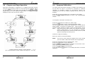
1
mn100
Dual Digital Display
uu037 rev. 8
mn100 Dual Digital Display
EMC Conformance
All Tacktick equipment is designed to the best industry standards for
use in the recreational marine environment. The design and
manufacture of Tacktick equipment conforms to the appropriate
Electromagnetic Compatibility (EMC) standards. Correct installation is
required to ensure that performance is not compromised.
Important
Due to the wireless communication systems used in Micronet
instruments they are only recommended for use on boats up to 14
meters (45 ft.) which are of glass, carbon, or wooden construction.
Like any other Electronic instruments your Micronet system is
designed to serve only as an aid to navigation and it remains the
skippers responsibility to maintain a permanent watch and be aware
of developing situations.
mn100 Dual Digital Display
Introduction
6.2.10 No NMEA data showing on external instruments.
From any Digital instrument enter Setup and Calibration Mode (page
18) and scroll through to the Health Chapter. Check the signal level
and battery status of the NMEA Interface. If the signal level shows a
value of greater than 3 then check the data connections and the
settings of the NMEA source equipment to ensure that NMEA 0183 is
being transmitted correctly.
*
The “Master Instrument” is the instrument which was used to power up
the entire system. This instrument may be different each time the
system is used. If you are fault finding and are uncertain which
instrument is the master the switch off the system and switch on again.
The instrument which you switched on is now the master
Warranty Information
Tacktick Limited or its authorized Distributors will repair or replace a
Tacktick product free of charge where a manufacturing fault becomes
apparent within two years of the purchase date provided:
1.
No unauthorized attempt has been made to repair the
product.
2.
The product has not been misused, operated outside of its
intended environment or operated in a manner which is
incompatible with the written instructions supplied on
purchase.
1
1.1
1.2
1.3
1.5
2
3
Setup and Calibration
3.1
3.2
3.3
3.4
3.5
4
Due to the removable nature of the Tacktick product, on board service
will only be available with prior consent from Tacktick or its authorized
Distributors.
5
Failure within the warranty period:
Simply return the product to your nearest authorized Tacktick
Distributor, together with proof of purchase date.
5.1
5.2
5.3
5.4
5.5
Failure outside the warranty period:
Simply return your product to the nearest authorized Tacktick
Distributor and an estimation for repair will be provided.
6
36
6.1
6.2
6.3
-
2
2
2
5
-
5
6
6
7
8
10
-
18
18
19
20
22
-
26
27
28
29
-
30
30
31
33
33
Operation
Instrument Display Information
Switching the System On and Off
Backlighting
Audible Signals and Alarms
Chapter and Page Operation
Chapter and Page Description
4.1
4.2
4.3
4.4
at
Introduction
Specifications
Power Management and Battery Life
Safety and Disposal
2.1
2.2
2.3
2.4
2.5
2.6
Proof of purchase date is required for the warranty period to
be valid.
Authorized
Tacktick
Distributor
details
can
be
found
www.tacktick.com, or on the back of Tacktick sales brochures.
Information
Entering Setup and Calibration Mode
Chapter and Page Setup and Calibration
Editing Values
Setup Page Description
Calibration Page Description
Seatrial and Calibration
Depth Offset
Speed Calibration
Wind Calibration
Compass Calibration
Installation
Tools List & Parts
Precautions and Positioning Advise
Bracket Mounting
Surface Mounting
External Power Connections
Maintenance and Fault Finding
Care and Maintenance
Fault Finding and Technical Support
Warranty Information
-
34
34
37
1
mn100 Dual Digital Display
6.2.4 Low Battery Alarm sounds.
The power level is low in the Hull Transmitter, NMEA Interface or Wind
Transmitter. On any Digital Instrument enter Setup and Calibration
mode (Page 18) and scroll through to the Health Chapter. Check the
1 - Information
1.1
Introduction
Your Micronet instrument is powered for life by the environment.
Although feature packed and highly visible in all conditions, current
demand is so low, and the supply so efficient, that the solar-powered
display is self sufficient. Combined with other instruments in the
Micronet range this display becomes part of a complete navigational
system.
1.2
Specifications
Height of digits:
Backlighting:
Power:
Units of display:
Alarm:
Weight:
Operating Temp.:
Frequency:
1.3
20mm (0.8”)
3 levels with daylight shutoff
System-wide or local control
Solar Powered
300 hrs autonomy by day, 7 nights at brightest
backlighting, 20 nights at economy backlighting
without charge
Boat Speed
(knots,kilometers per hour,statute miles per hour)
Distance
(nautical miles, statute miles, kilometers)
Depth
(meters, feet, fathoms)
Wind Speed
(knots, meters per second, Beaufort)
Audible Alarm for Depth, Wind and MOB
285g (0.63lbs)
-100 to +600C (140 to 1400F)
868 MHz or 905 MHz
Power Management and Battery Life
What makes your mn100 instrument possible is Tacktick’s
revolutionary approach to power management. By reducing the
amount of power being used by the electronics and maximizing the
potential of the sun to provide power, a mn100 instrument becomes a
virtually perpetual device.
Power status is indicated by two icons on the instrument display:
Battery Level
and
Charge Rate
Used together these icons will show the condition of your instrument’s
power supply.
2
Maintenance and Fault Finding
signal levels of the Transmitters and Interface Box. The signal level
should show a value of greater than 3 to ensure correct operation.
Connect the Hull Transmitter or NMEA Interface to a 9 to 24V power
source for 12 hours minimum to recharge the internal battery. Leave
the Wind Transmitter in bright sunlight for 12 hours minimum to
recharge its internal battery.
6.2.5 Data is shown as dashes.
The information is not been transmitted to the instrument Displays.
There may be lost communication between the Wind Transmitter or
Hull Transmitter and the instrument Displays. On any Digital
instrument enter Setup and Calibration mode (page 18) and scroll
through to the Health Chapter. Check the signal levels of the Hull and
Wind Transmitters. The signal level should show a value of greater than
3 to ensure correct operation.
6.2.6 Compass Transducer rattles and/or splashes.
Good! The fluxgate compass is gimballed in a fluid filled container to
ensure it is not affected by the boats movement in the water.
6.2.7 Compass information displayed on the instrument system does
not agree with the main steering compass.
Ensure that the main steering compass has been swung correctly and is
showing correct information. Ensure that the instrument system has
completed correctly the “Swing” procedure described on page 29. If
there are still differences, look for magnetic objects (loud speakers,
pumps and motors, etc.) close to the Transducer and try mounting the
compass transducer in an alternative location. After changing position
of nearby equipment or the Compass Transducer it will be necessary to
re-swing the compass following the procedure on page 29.
6.2.8 Boat Speed reads 0.
Information being transmitted from the Hull Transmitter is being
received with a Zero value. Check the paddle wheel for fouling, clean it
and make sure it turns easily.
6.2.9 Wind Speed reads 0.
Information being transmitted from the Wind Transmitter is being
received with a Zero value. If the anemometer cups at the top of the
mast are turning and the Wind Speed reads 0 then there is a problem
with your Wind Transmitter.
6.2.11 The Depth Alarm does not sound.
If the actual water depth is shallow and the alarm has not sounded it is
most likely that the alarm is switched off. From any Digital instrument
enter Setup and Calibration mode (page 18) and scroll through to the
Depth Chapter. Ensure the Depth Alarm settings are correct.
35
mn100 Dual Digital Display
5.4
Surface Mounting
Operation
2 – Operation
5.4.1 Where there is no access to the rear of the
mounting surface
Easy installation but will allow removal without gaining access to the
boat. Position the supplied Template carefully before starting.
1.
Drill three 2mm holes marked “SURFACE” on the Template
2.
Carefully snap the facia of the instrument off the main body
taking care not to drop the button pads. .
HINT – It may be useful to place a piece of sticky tape
across the front of the buttons before removing the facia to
prevent them from falling out during the installation.
3.
Remove the three captive M4 nuts from the plastic moulding
and attach the instrument to the mounting surface using the
three self tapping screws provided. Take care not to over
tighten the screws as this may cause the moulding to crack.
4.
Check the instrument is perfectly level, carefully position the
button inserts into the correct slots and snap the facia back
into position.
Important:
Ensure that the “Auto Network” procedure described on the yellow
instruction sheet and full Setup and Calibration has been performed
correctly before attempting to use your Micronet instruments for
navigation purposes.
2.1
Instrument Display Information
5.4.2 Temporary Mounting
1.
Note:
32
Use the double sided tape provided to secure the instrument
to a suitable mounting surface. Press the instrument firmly
against the surface until secure.
This method is recommended for temporary use only.
5
mn100 Dual Digital Display
If there is no boat speed or change in heading registered on the
system for a period of 12 hours your Micronet instrument will switch
off to conserve power. A “POWER SAVE” alarm will sound before the
instrument system is switched off. Pressing any button within 10
seconds of the alarm sounding will allow the system to remain
switched on.
Backlighting will automatically shut down/off when operated in
daylight.
Artificial light WILL NOT recharge the battery. Placing
your Micronet instrument close to an artificial light will
seriously damage the instrument. Only recharge in natural
daylight.
Installation
5.4.3 Where access is available to the rear of the
mounting surface
This method allows for maximum security of a permanently mounted
instrument. Position the supplied Template carefully before starting.
1.
Drill three 5mm holes marked “B” on the Template.
2
Stick the 3 supplied gaskets on the back of the instrument.
3.
Screw the four M4 brass studs into the rear of the
instrument.
4.
Place the instrument in position pushing the three studs
through the newly drilled holes.
5.
Using the three supplied thumb nuts, secure the instrument
to the surface making sure the instrument is level before
final tightening.
Applying External Power
In cases where instruments are mounted permanently below decks it
will be necessary to apply an external power source to prevent
complete discharge of the built in battery.
Connections on the rear of the instrument allow a 9V to 24V DC power
source to be connected. Connections can be made to the vessels DC
system or a 9V battery pack may be connected. It is recommended
that permanent connection is only made when the instruments are
permanently fixed to the vessel and not when the clip brackets are
used.
Connection to a 9V (PP3) battery will fully recharge the internal
battery over a period of 24 hours.
1.4
Safety and Disposal
Your Micronet instrument contains Manganese Lithium Dioxide
batteries which should be disposed of correctly. Do not dispose of any
instrument in domestic waste. Refer to regulations in force in your
country.
If in doubt return the instrument to Tacktick Ltd. for correct disposal.
5.5
To connect an external 9 to 24 volt power supply to the instrument
head from either a portable battery or the vessel’s existing power
system.
1.
2.
3.
4
5.
6.
7.
4
External Power Connections
Drill two 7mm holes marked “P” on the Mounting Template
and smooth them together with a sharp knife or small file.
Pass the supply cable through the new hole and attach the
supplied crimp spade receptacles.
Remove the blanking plug from the rear of the instrument to
expose the terminals.
Stick the supplied gasket on the back of the instrument.
Taking care to connect the correct polarity push the
receptacles firmly onto the spades on the rear of the case.
Mount the instrument head securely in position following the
steps shown above.
Clamp the cable securely close to the instrument.
33
mn100 Dual Digital Display
6
Introduction
Maintenance and Fault Finding
6.1 Care and Maintenance
All Micronet products are totally sealed against water and are not
serviceable. Any attempt to take a Micronet product apart will
invalidate the warranty.
Bright
Day
Sunny
Overcast Day
To clean, use only a damp, soft cloth. No detergents, solvents or
abrasives should be used. To avoid damaging a Micronet display unit
we recommend storing in the supplied soft pack when not in use.
If the instruments are to be stored for a long period of time before
next use (Over Winter) ensure that the batteries are fully charged
before storage. If necessary connect to a 9 to 24v power supply for
24 hrs prior to storage.
Night
and
Battery is charged and
topped up by the sun. *
and
Battery is low and being charged
by the sun.
and
Battery is charged and requires no
further charging.
and
Battery is low but maintaining it’s
level.
and
Battery is
charging.
and
6.2 Fault Finding and Technical Support
6.2.1 Power Save Alarm sounds.
There has been no significant data activity on the network. The alarm
sounds to indicate that the instrument system will turn itself off. To
continue using the system press any button to cancel the alarm.
6.2.2 Lost Network Alarm sounds.
On a single instrument this indicates that the particular instrument has
lost communication with the Master*. Either there is a problem with the
Master* instrument or the instrument in question has been moved out
of effective range.
On several instruments this indicates that these instruments have lost
communication with the Master*. Either there is a problem with the
master or the Master* has been moved out of effective range. The
instruments will power down shortly after sounding the alarm to save
power.
6.2.3 A single instrument flashes the battery symbol
and then
switches off.
The battery level is low on the particular instrument affected. Connect
to a 9 to 24V power source or leave in bright sunlight for 12 hours
minimum to recharge the instrument’s internal battery. If the particular
instrument is the system Master* then the other instruments will sound
the Lost Network Alarm. To continue using the rest of the system
power down and restart the system from another instrument.
34
LOW Power
and
Flashing
charged
but
being
is
not
Battery is low with no charging.
It is recommended that the
instrument be left in daylight for
some time for the battery to
recover, or charge from an
external 9 - 24V power source. A
fully discharged battery will recharge in approximately 12 hours
of direct bright sunlight.
If using the instruments at night power usage can be reduced
dramatically by switching the Backlighting to level 1 or Off. If
Backlighting is not required on instruments located below decks it is
best to set them to “Local” Backlighting control (see page 26 -s31) so
that power is not being wasted in instruments which may not be
visible from the one being viewed.
*
If the internal battery is fully charged then it does not matter
how much the instrument is subjected to bright sunlight no further
charging is required and the Charge Rate Indicator will remain low.
If the instruments are to be stored for a long period of time before
next use (Over Winter) ensure that the batteries are fully charged
before storage. If necessary connect to a 9 to 24v power supply for
24 hrs prior to storage.
3
mn100 Dual Digital Display
2.2
Switching the System On and Off
To switch on your Micronet
system select any instrument
and press the
button for 2
seconds.
To switch off your Micronet
system select any instrument
and press and hold the
button for 2 seconds.
2.3
Installation
5.3
Bracket Mounting (Preferred Method)
This method allows for the easy removal of an instrument as and
when required, for either security reasons or to prevent damage or
discomfort whilst not in use.
1.
Using the three supplied M4 bolts attach the back plate to
the rear of the instrument (Fig.1).
2.
Drill three 2mm holes marked “BRACKET” on the Template
and using the supplied self tapping screws attach the clip
bracket to the mounting surface (Fig.2).
3.
Place the instrument flat against the bracket slightly higher
than the final position and slide gently down into position.
There will be a small click as the bracket secures the
instrument into position (Fig.3).
4.
To release the instrument press lightly on the bracket tab
and slide the instrument upwards (Fig.4).
Backlighting
At any stage of the instrument’s
operation press and hold for 2
seconds the
button to
access the lighting control.
Pressing the
and
buttons
will
scroll
through
setting OFF, 1, 2 and 3 whilst
changing
the
Backlighting.
Depending on the instrument
setup (see page 20 -s5),
Backlighting
on
the
whole
system or just the single
instrument will be altered.
Backlighting is automatically switched off in daylight as part of
the instrument’s power saving feature and will not operate in daylight.
6
31
mn100 Dual Digital Display
5
Installation
5.1
Tools Required and
1. 2mm or 5mm Drill Bit (7mm
if power connection required)
2. Power Drill
3. Cross Head Screwdriver
5.2
Operation
2.4
Parts List
1.
2.
3.
4.
5.
6.
7.
Mounting Template
Display Bracket
Mounting Screws (3)
Mounting Bolts (3)
M4 Studs & Thumbnuts (3)
Sealing Gaskets (4)
Double Sided Tape
Precautions and Positioning Advice
Ensure mounting surface is flat.
Leave space between instruments for sun covers.
Leave space to remove instrument from bracket (if used).
Avoid areas where damage may occur (winch handles ,feet, warps
etc.)
Select a flat, smooth, surface for mounting and use the Template
provided to select a suitable position for mounting your Micronet
instrument.
Check for clarity of vision and ease of access to the control buttons, it
is recommended that instruments are positioned such that your arm
does NOT pass through the spokes of the steering wheel when
operating the buttons.
Audible Signals and Alarms
At stages during its operation your Micronet instrument will beep to
indicate alarms or moments of importance.
Power-up
Once operating as part of a network the instrument
will issue a single beep as it is switched on by
pressing the
button for 2 second.
Button Press A single beep is issued each time a button is pressed
A second beep is issued after a 2 seconds hold down
of the
button.
Alarm
Continuous bursts of three beeps will indicate an
alarm. The alarm activated will be indicated on the
digital display, accompanied by the flashing
symbol. Pressing any button will silence the alarm.
Timer
A single beep will be issued at each minute of the
countdown. With 1 minute left to go a beep will sound
every 10 seconds. With 10 seconds to go a beep will
sound every second.
Countdown complete will be indicated by a single
burst of three beeps.
Contrast is limited at night when an instrument is
viewed from beneath. Avoid mounting instruments in a
position where you will look upwards to view them.
30
7
mn100 Dual Digital Display
2.5
Chapter and Page Operation
Instrument information is displayed in a “Chapter and Page” format
using the
(Chapter) button to scroll through the Chapters which
are displayed in the upper part of the window and the
and
(Page) buttons to move between Pages within a Chapter which are
displayed in the lower part of the window.
Setup and Calibration
4.4
Compass Calibration
To ensure that inaccuracies caused by metallic and magnetic objects
on the boat are kept to a minimum is necessary to calibrate the
compass. A deviation caused by surrounding objects will be
compensated for and the compass reading may be set to the correct
heading.
Press and hold the
button for 2 seconds to enter Setup
Press the
button repeatedly to scroll to the “SETUP/COMPASS”
Chapter
To Complete a deviation correction turn:
Press the
button to advance to “DEV0” Page
Press the
button to enter Compass Calibration Mode
Turn the vessel slowly keeping the speed below 4 knots and taking
approximately 2 minutes to complete 3600 . Keep turning the vessel
until the display changes to display a value (usually about 1.25 turns)
Note:
If the rate of turn of the vessel is too fast the instrument will
display “TURN HIGH”. It is not necessary to abandon the
turn at this stage but do lessen the rate of turn by reducing
speed or widening the turning circle.
Continue to align the heading
Steer the vessel on a known heading.
Note:
only use the main steering compass as a known heading if
you are certain it has been checked and compensated.
Press the
button twice to display HDG / +000
Press the
button to enter Edit Mode
Press the
and
buttons to change to the known value. The
lower digits will display the offset entered.
Press the
button to exit Edit Mode
Press and hold the
button to exit Setup and return to normal
operation.
Chapter Sequence Shown in Upper Window
(for a full description of each Chapter see page 10 - c1 to c8)
8
29
mn100 Dual Digital Display
4.3
Wind Calibration
Both Wind Speed and Direction can be calibrated to ensure that
readings from the Wind Transmitter are displayed accurately.
4.3.1 Wind Angle Offset
Motor the vessel directly into the wind.
Press and hold the
button for 2 seconds to enter Setup
Press the
button repeatedly to scroll to the “SETUP/WIND”
Chapter
Press the
button to advance to “WIND/+0000” Page
Press the
button to enter Edit Mode
Press the
and
buttons to change the displayed value to
000.
The bottom digits will indicate the number of degrees of offset
entered.
Press the
button to exit Edit Mode
Press and hold the
button to exit Setup and return to normal
operation.
Operation
It is possible to select any Page (lower window) within any Chapter
(upper window) giving you a chance to display any two pieces of
information available at any time. Once a Page display has been
selected within a Chapter the same Page will be displayed every
rollover of the Chapter sequence ensuring that you return to your
choice of display within a maximum of 8 presses of the
(Chapter)
button.
4.3.2 Wind Speed Correction
Note:
Wind Speed reading is factory calibrated to display correctly
and should not be altered unless external factors are thought
to be causing incorrect readings. Correction should only be
carried out if a known correct Wind Speed is available.
Press and hold the
button for 2 seconds to enter Setup
Press the
button repeatedly to scroll to the “SETUP/WIND”
Chapter
Press the
button to advance to “WIND/+0%” Page
button to enter Edit Mode
Press the
Press the
and
buttons to change the displayed value to the
required percentage.
The bottom digits will indicate the displayed Wind Speed.
Press the
button to exit Edit Mode
Press and hold the
button to exit Setup and return to normal
operation.
28
Full Page Selection List Shown in Lower Window
(for a full description of each Page see page 11 -p1 to p32)
9
mn100 Dual Digital Display
2.6
Chapter and Page Descriptions
2.5.1 Chapters
(c1)
DEPTH
The Actual Depth beneath the vessel as measured by the
Depth Transducer. The displayed value will be affected by
any keel or waterline offset added (see page 23).
(c2)
APP WIND Speed
The Actual Wind Speed with respect to the vessel as
measured by the Wind Transmitter.
(c3)
SPEED
The vessels actual speed through the water as measured by
the Speed Transducer.
(c4)
MAG HDG
Current Magnetic Compass Heading of the vessel as
measured by the Compass Transducer. The value displayed
will be affected by the calibration routine for the compass
(see page 26).
(c5)
TRUE WIND Speed
The True Wind Speed with respect to the vessel, calculated
by the instrument taking into account the vessels speed
through the water. Both Apparent Wind Speed, Angle and
Boat Speed must be available for this calculation.
(c6)
COG
Course Over the Ground as calculated by the GPS Antenna.
(c7)
BTW
Bearing To (active) Waypoint. The active Waypoint being the
one to which the GPS is currently navigating.
(c8)
PROG (Custom Chapter)
A Custom Chapter which allows you to select from a full list,
the information you wish to display in the Chapter (upper)
window (see page 21 -s30 for selection).
10
Setup and Calibration
4.2
Speed Calibration
To ensure that the Boat Speed (and Distance) is accurate it is
necessary to calibrate the speed to take into account variations in
water flow between different hulls. Adjustment is made by multiplying
the Speed through the Water (V) by a percentage Calibration Factor.
It is essential to carry out this procedure at a time where little or no
tide is flowing.
To enter a Log Calibration Factor
With the vessel under power, steer a straight course allowing the Boat
Speed reading to settle to a constant value. Check the GPS is showing
a constant SOG.
Press and hold the
button for 2 seconds to enter Setup
Press the
button repeatedly to scroll to the “SETUP/SPEED”
Chapter
Press the
button to advance to “SPEED/+0%” Page
Press the
button to enter Edit Mode
Press the
and
buttons to change the Calibration Factor until
the Speed reading displayed matches the GPS SOG reading
Press the
button to exit Edit Mode
button to exit Setup and return to normal
Press and hold the
operation.
Should you be unable to carry out this procedure due to strong tidal
conditions or poor GPS information there is further information
regarding Speed Calibration using a measured distance on the
Tacktick website at www.tacktick.com.
27
mn100 Dual Digital Display
Operation
4 - Seatrial and Calibration
2.5.2 Pages
Once the Micronet Instrument system has been installed on the vessel
and Auto Networking has been completed it is necessary to carry out
Calibration.
(p1)
SPEED
The vessels Actual Speed through the water as measured by
the Speed Transducer.
It is not safe to use the instruments for navigational
purposes until Calibration has been carried out
correctly.
(p2)
VMG
The vessels calculated Speed Directly Upwind. This value is
calculated by the instrument from the Boat Speed and
Apparent Wind Angle.
(p3)
VMG-WP
The vessels calculated Speed directly towards the active
Waypoint. This value is calculated by the GPS Antenna.
(p4)
LOG
The total distance travelled by the vessel since installation of
the instrument or since a Factory Reset.
(p5)
TRIP
The distance travelled since the last Trip Reset. To Reset see
page 18 -s1.
(p6)
MAX Speed
The Maximum Speed attained since the last reset. To Reset
see page 18 -s4.
(p7)
AVG Speed
The Average Speed attained since the last reset. To Reset
see page 18 -s5.
(p8)
DEPTH
The Actual Depth beneath the vessel as measured by the
Depth Transducer. The displayed value will be affected by
any keel or waterline offset added (see page 23).
(p9)
MIN Depth
The Minimum Depth encountered since switch on or since
the last Minimum Depth Reset. To Reset see page 18 -s2.
(p10)
MAX Depth
The Maximum Depth encountered since switch on or since
the last Maximum Depth Reset. To Reset see page 18 -s3.
(p11)
APP WIND Speed
The Actual Wind Speed with respect to the vessel as
measured by the Wind Transmitter.
4.1
Depth Offset
The default depth offset is 0.0 making the instrument read the Depth
below the Transducer. By adding a +ve or -ve offset the instrument
will display the waterline depth or depth below the keel respectively.
button for 2 seconds to enter Setup
Press and hold the
Press the
button repeatedly to scroll to the “SETUP/DEPTH”
Chapter
Press
button to advance to the “KEEL / WLINE” Page
Press the
button to enter Edit Mode
Press the
and
buttons to change the value
Press the
button to exit Edit Mode
Press and hold the
button to exit Setup and return to normal
operation.
26
11
mn100 Dual Digital Display
(p12)
APP WIND Angle
The Actual Wind Angle with respect to the vessel as
measured by the Wind Transmitter.
(p13)
TRUE WIND Speed
The True Wind Speed with respect to the vessel, calculated
by the instrument taking into account the vessels speed
through the water. Both Apparent Wind Speed, Angle and
Boat Speed must be available on the network for this
calculation.
(p14)
TRUE WIND Angle
The True Wind Angle with respect to the vessel, calculated
by the instrument taking into account the vessels speed
through the water. Both Apparent Wind Speed, Angle and
Boat Speed must be available on the network for this
calculation.
(p15)
(p16)
(p17
MAG TWDIR
The Actual Wind Direction over the water, calculated by the
instrument taking into account the vessels speed through the
water and compass heading. Apparent Wind Speed, Direction
and Compass Heading must be available on the network for
this calculation.
Setup and Calibration
Health Chapter
(s37)
VER / NODES
Displays the instrument’s Software Version, battery level and
charge rate to assist in troubleshooting and fault finding. If
the instrument is the “Master” (the one used to switch on the
system) then the number of items (nodes) in the system will
be displayed. If the instrument is a “Slave” (was switched on
by the system) then the signal strength to the “Master” will
be displayed”
(s38)
HULL SIGNL
Shows the signal strength and battery level of the Hull
Transmitter to assist in troubleshooting and fault finding.
(s39)
WIND SIGNL
information)
(s40)
NMEA SIGNL (as above but for NMEA Interface information)
(as
above
but
for
Wind
Transmitter
(s41 --)Further signal strength indications will be displayed if
available.
BEAUF
The Actual Wind Speed over the water displayed using the
Beaufort scale, calculated by the instrument taking into
account the vessels speed through the water and compass
heading. Apparent Wind Speed, Direction and Compass
Heading must be available on the network for this
calculation.
SHIFT HEAD/ LIFT
Indicates changes in the wind against a compass heading.
Spotting these wind changes is the key to fast sailing
upwind.
To set the mean wind angle:
1.
12
If a Wind Transmitter is included in your Micronet system
then simply press the
button; (the current wind
direction is stored as the mean wind direction and displayed
for 5 seconds during which time the
and
buttons
may be used to adjust the value.)
25
mn100 Dual Digital Display
Options Chapter
(s30)
(s31)
MAG HDG
Current Magnetic Compass Heading of the vessel as
measured by the Compass Transducer. The value displayed
will be affected by the calibration routine for the compass
(see page 26).
(p19)
MAG TACK
Magnetic Compass heading which the vessel will follow
should it tack through the wind, calculated by the
instrument. Apparent Wind Angle and Magnetic Heading
must be available on the network for this calculation to be
made.
(p20)
SOG
Vessels Speed Over the Ground as calculated by the GPS
Antenna.
(p21)
RESET
Returns all the calibration setting to the factory default
values but does not reset your Auto Networking.
COG
Vessels Course Over the Ground as calculated by the GPS
Antenna.
(p22)
LAT
Vessels current Latitude as calculated by the GPS Antenna.
Only carry out a Reset after consulting with an
authorized Tacktick dealer.
(p23)
LON
Vessels current Longitude as calculated by the GPS Antenna.
(p24)
BTW
Bearing To (active) Waypoint. The active Waypoint being the
one to which the GPS is currently navigating.
LIGHT
Tells the instrument to control the system Backlighting or
just its own Backlighting. Network/Local.
24
See Tacktick’s “Using wind shifts to your advantage” sheet
for further information.
(p18)
(s33)
(s36)
If you do not have a Wind Transmitter included, sail close
hauled and press the
button then tack and, once close
hauled, press the
button again.
If the mean wind direction changes then the instrument may
be updated by press and holding the
button while
sailing on port tack, the
button while sailing on
starboard tack or the
button while head to wind.
CHAP PROG (lower window)
Allows one further selection to be added to the Chapter list
(see page 9). The current selection is indicated in the
Chapter window.
TIME
The number of hours added or subtracted from UTC (GMT) to
allow the instrument to display local time.
(s35)
2.
AUTO NETWK
Only available on the instrument which was used to power
up the system. Refer to the “Auto Network” sheet for further
information.
(s32)
(s34)
Operation
bOAt SHOW
Allows the instrument to display information when NOT
installed as part of a Micronet system for demonstration
purposes only. On/Off. This setting will reset to Off when the
instrument is switched off.
DISPL CONTR
Allows the contrast of the LCD display to be adjusted to suit
the viewing angle of the instrument. The lower the figure the
less contrast is visible. 1 - 7 default 4.
13
mn100 Dual Digital Display
(p25)
DTW
Distance To (active) Waypoint. The active Waypoint being
the one to which the GPS is currently navigating. When the
Waypoint has been named in the GPS the name will be
displayed (first five digits only).
(p25)
DTW
Distance To (active) Waypoint. The active Waypoint being
the one to which the GPS is currently navigating. When the
Waypoint has been named in the GPS the name will be
displayed (first five digits only).
(p26)
XTE
Cross Track Error as defined by the GPS Antenna.
(p27)
ETA
Estimated Time of Arrival at the (active) Waypoint as
calculated by the GPS Antenna.
Setup and Calibration
Wind Chapter
(s22)
RESP Wnd
Sets the update period of the Wind display.
Auto/Slow/Medium/Fast
(s23)
WIND (degrees)
Aligns the displayed Apparent Wind Angle with the Actual
Wind Direction with respect to the boat. See page 25 for
calibration.
(s24)
WIND (speed)
Adds a percentage factor which corrects the information
from the Wind Transmitter and ensures the Apparent Wind
Speed is displayed correctly. See page 24 for calibration.
Compass Chapter
(p28)
SEA
Current Sea Temperature as measured by the sensor in the
Speed Transducer.
(s25)
RESP HEAd
Sets the update period of the Compass display.
Auto/Slow/Medium/Fast
(p29)
TIMER
Countdown or elapsed time stopwatch.
Press and hold for 1 second the
button and use the
and
buttons to set the required countdown time in
minutes, then press and hold for 1 second the
button to
prepare to start the countdown.
Press the
button quickly to start the countdown.
The instrument will sound a single beep each 30 seconds
until 1 minute remains when a beep will sound at 10 second
intervals. The final 10 seconds will count down with a beep
each second with “START” being indicated by a triple quick
beep at 0. The timer will automatically start to count the
elapsed time and this will continue until the
button is
pressed and held for one second.
At any stage a quick press of the
button will
resynchronise the timer to the nearest full minute and then
carry on the count down.
(s26)
HDG (Mag/True)
Tells the instrument to display heading information in either
Magnetic or True format.
(s27)
HDG (degrees)
Aligns the displayed heading with the Actual Magnetic
Heading of the boat. See page 26 for calibration.
(s28)
VAR
Allows manual entry of local magnetic variation. This setting
is ignored if variation information is available from a GPS
source.
(s29)
DEV
However carefully positioned the Compass Transducer is,
there is always the likelihood of errors being introduced by
the vessel and equipment. To remove errors it is necessary
to “Swing” the compass by turning the boat slowly until the
system can optimize the readings. Once the correction has
been completed the deviation correction value will be
displayed. See page 26 for calibration.
Example:
Press
Press
14
at 3mins 24secs the timer will reset to 3mins 0secs
at 7mins 52secs the timer will reset to 8mins 0secs
23
mn100 Dual Digital Display
(s15)
XTE LARGE
Sets the instrument to alarm if a Large Cross Track Error
alarm is issued by the GPS. On/Off.
(s16)
WP ARRVE
Sets the instrument to alarm if a Waypoint Arrival alarm is
issued by the GPS. On/Off.
3.5
Calibration Page Description
In each case press the
button quickly to edit, press the
or
to change units and press the
button quickly to select the
chosen units. Default values are indicated in bold.
Speed Chapter
(s17)
RESP Spd
Sets the update period of the Speed display.
Auto/Slow/Medium/Fast
(s18)
SPEED
Boat Speed Calibration Factor adds a percentage factor
which corrects the information from the Speed Transducer
and ensures the Boat Speed is displayed correctly. See page
24 for calibration.
(s19) SPEED FORMT
Sets the display to show Speed readings in a resolution of
0.1 or 0.01 of the selected units.
(s20)
SEA
Sea Temperature Calibration Factor adds a percentage factor
which corrects the information from the temperature sensor
and ensures the water temperature is displayed correctly.
Depth Chapter
(s21)
22
Operation
KEEL OFSET
Allows a Keel Offset to be added allowing the instrument
depth reading to indicate depth below the bottom of the
boat, or a Waterline Offset allowing the depth reading to
indicate Actual Water Depth. See page 23 for calibration.
Press and hold for 1
second to enter the
timer setup
Select the desired
countdown time
Press and hold for 1
second to store the
countdown time
Press to start
Countdown time in
progress
Press to
resynchronise
to nearest full minute
(8:00)
(p30)
TIME
Current Time as received from the GPS Antenna corrected to
local time if an offset has been added (see page 22 -s31).
(p31)
DATE
Current date as received by the GPS Antenna.
15
mn100 Dual Digital Display
(p32)
Setup and Calibration
Target Page
Produces a “Trim” indication showing an increase or decrease
in value from a set point. First select the appropriate chapter
in the upper display using the button then select “Lock” in
the lower display using the or buttons. Pressing the button
will lock the upper display value and the lower display will
now indicate increase or decrease from the set value. Values
displayed as units will show a percentage (%) increase or
decrease whereas values displayed as degrees will show the
difference in degrees.
(s9)
LOG UNITS
The units in which ALL distance related information is
displayed. Nautical Miles (NM), Kilometres (KM) or Statute
Miles (SM).
(s10)
TEMP UNITS
The units in which the Sea Temperature reading is displayed.
Degrees Celsius (0C) or Degrees Fahrenheit (0F).
3.4.3 Alarms Chapter
In each case press the
button quickly to edit, press
to change values and press the
button quickly
entered value. In the case of On/Off selection the
toggle the setting On and Off. Default values are indicated
Heading locked at 2690 now
showing +008 change meaning
current heading is 2770
16
the
or
to save the
button will
in bold.
(s11)
DEPTH SHALL
Sets the Shallow Depth at which the instrument will alarm.
OFF and 0 to 7.6m (0 to 25 ft.) (0 to 4 ftms). Values are
displayed in the previously selected units (see page 18 -s7)
and are all subject to any keel or waterline offset added (see
page 20 -s21). This alarm sounds as the depth passes below
the set value and NOT as the depth increases past this
value.
(s12)
DEPTH DEEP
Sets the Deep Depth at which the instrument will alarm. OFF
and 0 to 76.2m (0 to 250 ft.) (0 to 41.6 ftms). Values are
displayed in the selected units (see page 18 -s7) and are all
subject to any keel or waterline offset added (see page 23).
This alarm sounds as the depth increases past this value or
decreases past this value.
(s13)
OFF CRSE
Sounds if the vessel moves further than the set distance
away from a “Locked” heading (see page 19 -s12). Off/On
(s14)
WIND HIGH
Sets the Wind Speed at which the instrument will alarm. OFF
and 0.0 to 100 knots (0.0 to 51.4 m/s). Values are displayed
in the previously selected units (see page 18 -s8). This alarm
sounds as the wind speed increases past the set value and
NOT as it decreases past this value.
Speed locked at 8.69 kts now
showing +10% change meaning
current speed is 9.56 kts)
21
mn100 Dual Digital Display
3.4
Operation
Setup Page Description
3.4.1 Memory Chapter
In each case press the
button quickly to reset.
(s1)
TRIP
The Distance Travelled since the last Trip Reset.
Resets to 0.00.
(s2)
DEPTH MIN
The Minimum Depth encountered since switch on or since
the last Minimum Depth Reset. Resets to Current Depth.
(s3)
DEPTH MAX
The Maximum Depth encountered since switch on or since
the last Maximum Depth Reset. Resets to Current Depth.
(s4)
SPEED MAX
The Maximum Speed attained since switch on or since the
last Maximum Speed Reset. Resets to Current Boat Speed.
(s5)
SPEED AVG
The average speed attained since switch on or since the last
Average Speed Reset. Reset to Current Boat Speed.
this page left intentionally blank
3.4.2 Units Chapter
In each case press the
button quickly to edit, press the
or
to change units and press the
button quickly to select the
chosen units. Default values are indicated in bold.
(s6)
SPEED UNITS
The units in which ALL speed related information is
displayed. Knots, Kilometres per hour (KPH) or Statute Miles
per hour (MPH).
(s7)
DEPTH UNITS
The units in which ALL depth related
displayed. Feet, Meters or Fathoms.
(s8)
WIND UNITS
The units in which ALL wind speed related information is
displayed. Knots or Meters per second (M/S).
20
information
is
17
mn100 Dual Digital Display
Setup and Calibration
3 - Setup and Calibration
3.3
3.1
To adjust any settings press the
button. The setting will start to
flash and the
and
buttons will change the value.
Entering Setup and Calibration Mode
Editing Values
To enter the Setup and Calibration menu press and hold for 2 seconds
the
button.
This will not work when in the Race Timer page.
3.2
Chapter and Page
Setup and Calibration
Instrument
Setup
and
Calibration is displayed in a
“Chapter and Page” format
using the
button to scroll
through the Chapters and the
and
buttons to move
between Pages. The diagram
below shows the information
format.
Note:
Unlike
normal
operation you must
scroll to the Chapter
heading page before
moving to another
chapter.
For a full description of each
Page refer to items s1 to s41
on the following pages
18
19
mn100 Dual Digital Display
(p32)
Setup and Calibration
Target Page
Produces a “Trim” indication showing an increase or decrease
in value from a set point. First select the appropriate chapter
in the upper display using the button then select “Lock” in
the lower display using the or buttons. Pressing the button
will lock the upper display value and the lower display will
now indicate increase or decrease from the set value. Values
displayed as units will show a percentage (%) increase or
decrease whereas values displayed as degrees will show the
difference in degrees.
(s9)
LOG UNITS
The units in which ALL distance related information is
displayed. Nautical Miles (NM), Kilometres (KM) or Statute
Miles (SM).
(s10)
TEMP UNITS
The units in which the Sea Temperature reading is displayed.
Degrees Celsius (0C) or Degrees Fahrenheit (0F).
3.4.3 Alarms Chapter
In each case press the
button quickly to edit, press
to change values and press the
button quickly
entered value. In the case of On/Off selection the
toggle the setting On and Off. Default values are indicated
Heading locked at 2690 now
showing +008 change meaning
current heading is 2770
16
the
or
to save the
button will
in bold.
(s11)
DEPTH SHALL
Sets the Shallow Depth at which the instrument will alarm.
OFF and 0 to 7.6m (0 to 25 ft.) (0 to 4 ftms). Values are
displayed in the previously selected units (see page 18 -s7)
and are all subject to any keel or waterline offset added (see
page 20 -s21). This alarm sounds as the depth passes below
the set value and NOT as the depth increases past this
value.
(s12)
DEPTH DEEP
Sets the Deep Depth at which the instrument will alarm. OFF
and 0 to 76.2m (0 to 250 ft.) (0 to 41.6 ftms). Values are
displayed in the selected units (see page 18 -s7) and are all
subject to any keel or waterline offset added (see page 23).
This alarm sounds as the depth increases past this value or
decreases past this value.
(s13)
OFF CRSE
Sounds if the vessel moves further than the set distance
away from a “Locked” heading (see page 19 -s12). Off/On
(s14)
WIND HIGH
Sets the Wind Speed at which the instrument will alarm. OFF
and 0.0 to 100 knots (0.0 to 51.4 m/s). Values are displayed
in the previously selected units (see page 18 -s8). This alarm
sounds as the wind speed increases past the set value and
NOT as it decreases past this value.
Speed locked at 8.69 kts now
showing +10% change meaning
current speed is 9.56 kts)
21
mn100 Dual Digital Display
3.4
Operation
Setup Page Description
3.4.1 Memory Chapter
In each case press the
button quickly to reset.
(s1)
TRIP
The Distance Travelled since the last Trip Reset.
Resets to 0.00.
(s2)
DEPTH MIN
The Minimum Depth encountered since switch on or since
the last Minimum Depth Reset. Resets to Current Depth.
(s3)
DEPTH MAX
The Maximum Depth encountered since switch on or since
the last Maximum Depth Reset. Resets to Current Depth.
(s4)
SPEED MAX
The Maximum Speed attained since switch on or since the
last Maximum Speed Reset. Resets to Current Boat Speed.
(s5)
SPEED AVG
The average speed attained since switch on or since the last
Average Speed Reset. Reset to Current Boat Speed.
this page left intentionally blank
3.4.2 Units Chapter
In each case press the
button quickly to edit, press the
or
to change units and press the
button quickly to select the
chosen units. Default values are indicated in bold.
(s6)
SPEED UNITS
The units in which ALL speed related information is
displayed. Knots, Kilometres per hour (KPH) or Statute Miles
per hour (MPH).
(s7)
DEPTH UNITS
The units in which ALL depth related
displayed. Feet, Meters or Fathoms.
(s8)
WIND UNITS
The units in which ALL wind speed related information is
displayed. Knots or Meters per second (M/S).
20
information
is
17
mn100 Dual Digital Display
(s15)
XTE LARGE
Sets the instrument to alarm if a Large Cross Track Error
alarm is issued by the GPS. On/Off.
(s16)
WP ARRVE
Sets the instrument to alarm if a Waypoint Arrival alarm is
issued by the GPS. On/Off.
3.5
Calibration Page Description
In each case press the
button quickly to edit, press the
or
to change units and press the
button quickly to select the
chosen units. Default values are indicated in bold.
Speed Chapter
(s17)
RESP Spd
Sets the update period of the Speed display.
Auto/Slow/Medium/Fast
(s18)
SPEED
Boat Speed Calibration Factor adds a percentage factor
which corrects the information from the Speed Transducer
and ensures the Boat Speed is displayed correctly. See page
24 for calibration.
(s19) SPEED FORMT
Sets the display to show Speed readings in a resolution of
0.1 or 0.01 of the selected units.
(s20)
SEA
Sea Temperature Calibration Factor adds a percentage factor
which corrects the information from the temperature sensor
and ensures the water temperature is displayed correctly.
Depth Chapter
(s21)
22
Operation
KEEL OFSET
Allows a Keel Offset to be added allowing the instrument
depth reading to indicate depth below the bottom of the
boat, or a Waterline Offset allowing the depth reading to
indicate Actual Water Depth. See page 23 for calibration.
Press and hold for 1
second to enter the
timer setup
Select the desired
countdown time
Press and hold for 1
second to store the
countdown time
Press to start
Countdown time in
progress
Press to
resynchronise
to nearest full minute
(8:00)
(p30)
TIME
Current Time as received from the GPS Antenna corrected to
local time if an offset has been added (see page 22 -s31).
(p31)
DATE
Current date as received by the GPS Antenna.
15
mn100 Dual Digital Display
(p25)
DTW
Distance To (active) Waypoint. The active Waypoint being
the one to which the GPS is currently navigating. When the
Waypoint has been named in the GPS the name will be
displayed (first five digits only).
(p25)
DTW
Distance To (active) Waypoint. The active Waypoint being
the one to which the GPS is currently navigating. When the
Waypoint has been named in the GPS the name will be
displayed (first five digits only).
(p26)
XTE
Cross Track Error as defined by the GPS Antenna.
(p27)
ETA
Estimated Time of Arrival at the (active) Waypoint as
calculated by the GPS Antenna.
Setup and Calibration
Wind Chapter
(s22)
RESP Wnd
Sets the update period of the Wind display.
Auto/Slow/Medium/Fast
(s23)
WIND (degrees)
Aligns the displayed Apparent Wind Angle with the Actual
Wind Direction with respect to the boat. See page 25 for
calibration.
(s24)
WIND (speed)
Adds a percentage factor which corrects the information
from the Wind Transmitter and ensures the Apparent Wind
Speed is displayed correctly. See page 24 for calibration.
Compass Chapter
(p28)
SEA
Current Sea Temperature as measured by the sensor in the
Speed Transducer.
(s25)
RESP HEAd
Sets the update period of the Compass display.
Auto/Slow/Medium/Fast
(p29)
TIMER
Countdown or elapsed time stopwatch.
Press and hold for 1 second the
button and use the
and
buttons to set the required countdown time in
minutes, then press and hold for 1 second the
button to
prepare to start the countdown.
Press the
button quickly to start the countdown.
The instrument will sound a single beep each 30 seconds
until 1 minute remains when a beep will sound at 10 second
intervals. The final 10 seconds will count down with a beep
each second with “START” being indicated by a triple quick
beep at 0. The timer will automatically start to count the
elapsed time and this will continue until the
button is
pressed and held for one second.
At any stage a quick press of the
button will
resynchronise the timer to the nearest full minute and then
carry on the count down.
(s26)
HDG (Mag/True)
Tells the instrument to display heading information in either
Magnetic or True format.
(s27)
HDG (degrees)
Aligns the displayed heading with the Actual Magnetic
Heading of the boat. See page 26 for calibration.
(s28)
VAR
Allows manual entry of local magnetic variation. This setting
is ignored if variation information is available from a GPS
source.
(s29)
DEV
However carefully positioned the Compass Transducer is,
there is always the likelihood of errors being introduced by
the vessel and equipment. To remove errors it is necessary
to “Swing” the compass by turning the boat slowly until the
system can optimize the readings. Once the correction has
been completed the deviation correction value will be
displayed. See page 26 for calibration.
Example:
Press
Press
14
at 3mins 24secs the timer will reset to 3mins 0secs
at 7mins 52secs the timer will reset to 8mins 0secs
23
mn100 Dual Digital Display
Options Chapter
(s30)
(s31)
MAG HDG
Current Magnetic Compass Heading of the vessel as
measured by the Compass Transducer. The value displayed
will be affected by the calibration routine for the compass
(see page 26).
(p19)
MAG TACK
Magnetic Compass heading which the vessel will follow
should it tack through the wind, calculated by the
instrument. Apparent Wind Angle and Magnetic Heading
must be available on the network for this calculation to be
made.
(p20)
SOG
Vessels Speed Over the Ground as calculated by the GPS
Antenna.
(p21)
RESET
Returns all the calibration setting to the factory default
values but does not reset your Auto Networking.
COG
Vessels Course Over the Ground as calculated by the GPS
Antenna.
(p22)
LAT
Vessels current Latitude as calculated by the GPS Antenna.
Only carry out a Reset after consulting with an
authorized Tacktick dealer.
(p23)
LON
Vessels current Longitude as calculated by the GPS Antenna.
(p24)
BTW
Bearing To (active) Waypoint. The active Waypoint being the
one to which the GPS is currently navigating.
LIGHT
Tells the instrument to control the system Backlighting or
just its own Backlighting. Network/Local.
24
See Tacktick’s “Using wind shifts to your advantage” sheet
for further information.
(p18)
(s33)
(s36)
If you do not have a Wind Transmitter included, sail close
hauled and press the
button then tack and, once close
hauled, press the
button again.
If the mean wind direction changes then the instrument may
be updated by press and holding the
button while
sailing on port tack, the
button while sailing on
starboard tack or the
button while head to wind.
CHAP PROG (lower window)
Allows one further selection to be added to the Chapter list
(see page 9). The current selection is indicated in the
Chapter window.
TIME
The number of hours added or subtracted from UTC (GMT) to
allow the instrument to display local time.
(s35)
2.
AUTO NETWK
Only available on the instrument which was used to power
up the system. Refer to the “Auto Network” sheet for further
information.
(s32)
(s34)
Operation
bOAt SHOW
Allows the instrument to display information when NOT
installed as part of a Micronet system for demonstration
purposes only. On/Off. This setting will reset to Off when the
instrument is switched off.
DISPL CONTR
Allows the contrast of the LCD display to be adjusted to suit
the viewing angle of the instrument. The lower the figure the
less contrast is visible. 1 - 7 default 4.
13
mn100 Dual Digital Display
(p12)
APP WIND Angle
The Actual Wind Angle with respect to the vessel as
measured by the Wind Transmitter.
(p13)
TRUE WIND Speed
The True Wind Speed with respect to the vessel, calculated
by the instrument taking into account the vessels speed
through the water. Both Apparent Wind Speed, Angle and
Boat Speed must be available on the network for this
calculation.
(p14)
TRUE WIND Angle
The True Wind Angle with respect to the vessel, calculated
by the instrument taking into account the vessels speed
through the water. Both Apparent Wind Speed, Angle and
Boat Speed must be available on the network for this
calculation.
(p15)
(p16)
(p17
MAG TWDIR
The Actual Wind Direction over the water, calculated by the
instrument taking into account the vessels speed through the
water and compass heading. Apparent Wind Speed, Direction
and Compass Heading must be available on the network for
this calculation.
Setup and Calibration
Health Chapter
(s37)
VER / NODES
Displays the instrument’s Software Version, battery level and
charge rate to assist in troubleshooting and fault finding. If
the instrument is the “Master” (the one used to switch on the
system) then the number of items (nodes) in the system will
be displayed. If the instrument is a “Slave” (was switched on
by the system) then the signal strength to the “Master” will
be displayed”
(s38)
HULL SIGNL
Shows the signal strength and battery level of the Hull
Transmitter to assist in troubleshooting and fault finding.
(s39)
WIND SIGNL
information)
(s40)
NMEA SIGNL (as above but for NMEA Interface information)
(as
above
but
for
Wind
Transmitter
(s41 --)Further signal strength indications will be displayed if
available.
BEAUF
The Actual Wind Speed over the water displayed using the
Beaufort scale, calculated by the instrument taking into
account the vessels speed through the water and compass
heading. Apparent Wind Speed, Direction and Compass
Heading must be available on the network for this
calculation.
SHIFT HEAD/ LIFT
Indicates changes in the wind against a compass heading.
Spotting these wind changes is the key to fast sailing
upwind.
To set the mean wind angle:
1.
12
If a Wind Transmitter is included in your Micronet system
then simply press the
button; (the current wind
direction is stored as the mean wind direction and displayed
for 5 seconds during which time the
and
buttons
may be used to adjust the value.)
25
mn100 Dual Digital Display
Operation
4 - Seatrial and Calibration
2.5.2 Pages
Once the Micronet Instrument system has been installed on the vessel
and Auto Networking has been completed it is necessary to carry out
Calibration.
(p1)
SPEED
The vessels Actual Speed through the water as measured by
the Speed Transducer.
It is not safe to use the instruments for navigational
purposes until Calibration has been carried out
correctly.
(p2)
VMG
The vessels calculated Speed Directly Upwind. This value is
calculated by the instrument from the Boat Speed and
Apparent Wind Angle.
(p3)
VMG-WP
The vessels calculated Speed directly towards the active
Waypoint. This value is calculated by the GPS Antenna.
(p4)
LOG
The total distance travelled by the vessel since installation of
the instrument or since a Factory Reset.
(p5)
TRIP
The distance travelled since the last Trip Reset. To Reset see
page 18 -s1.
(p6)
MAX Speed
The Maximum Speed attained since the last reset. To Reset
see page 18 -s4.
(p7)
AVG Speed
The Average Speed attained since the last reset. To Reset
see page 18 -s5.
(p8)
DEPTH
The Actual Depth beneath the vessel as measured by the
Depth Transducer. The displayed value will be affected by
any keel or waterline offset added (see page 23).
(p9)
MIN Depth
The Minimum Depth encountered since switch on or since
the last Minimum Depth Reset. To Reset see page 18 -s2.
(p10)
MAX Depth
The Maximum Depth encountered since switch on or since
the last Maximum Depth Reset. To Reset see page 18 -s3.
(p11)
APP WIND Speed
The Actual Wind Speed with respect to the vessel as
measured by the Wind Transmitter.
4.1
Depth Offset
The default depth offset is 0.0 making the instrument read the Depth
below the Transducer. By adding a +ve or -ve offset the instrument
will display the waterline depth or depth below the keel respectively.
button for 2 seconds to enter Setup
Press and hold the
Press the
button repeatedly to scroll to the “SETUP/DEPTH”
Chapter
Press
button to advance to the “KEEL / WLINE” Page
Press the
button to enter Edit Mode
Press the
and
buttons to change the value
Press the
button to exit Edit Mode
Press and hold the
button to exit Setup and return to normal
operation.
26
11
mn100 Dual Digital Display
2.6
Chapter and Page Descriptions
2.5.1 Chapters
(c1)
DEPTH
The Actual Depth beneath the vessel as measured by the
Depth Transducer. The displayed value will be affected by
any keel or waterline offset added (see page 23).
(c2)
APP WIND Speed
The Actual Wind Speed with respect to the vessel as
measured by the Wind Transmitter.
(c3)
SPEED
The vessels actual speed through the water as measured by
the Speed Transducer.
(c4)
MAG HDG
Current Magnetic Compass Heading of the vessel as
measured by the Compass Transducer. The value displayed
will be affected by the calibration routine for the compass
(see page 26).
(c5)
TRUE WIND Speed
The True Wind Speed with respect to the vessel, calculated
by the instrument taking into account the vessels speed
through the water. Both Apparent Wind Speed, Angle and
Boat Speed must be available for this calculation.
(c6)
COG
Course Over the Ground as calculated by the GPS Antenna.
(c7)
BTW
Bearing To (active) Waypoint. The active Waypoint being the
one to which the GPS is currently navigating.
(c8)
PROG (Custom Chapter)
A Custom Chapter which allows you to select from a full list,
the information you wish to display in the Chapter (upper)
window (see page 21 -s30 for selection).
10
Setup and Calibration
4.2
Speed Calibration
To ensure that the Boat Speed (and Distance) is accurate it is
necessary to calibrate the speed to take into account variations in
water flow between different hulls. Adjustment is made by multiplying
the Speed through the Water (V) by a percentage Calibration Factor.
It is essential to carry out this procedure at a time where little or no
tide is flowing.
To enter a Log Calibration Factor
With the vessel under power, steer a straight course allowing the Boat
Speed reading to settle to a constant value. Check the GPS is showing
a constant SOG.
Press and hold the
button for 2 seconds to enter Setup
Press the
button repeatedly to scroll to the “SETUP/SPEED”
Chapter
Press the
button to advance to “SPEED/+0%” Page
Press the
button to enter Edit Mode
Press the
and
buttons to change the Calibration Factor until
the Speed reading displayed matches the GPS SOG reading
Press the
button to exit Edit Mode
button to exit Setup and return to normal
Press and hold the
operation.
Should you be unable to carry out this procedure due to strong tidal
conditions or poor GPS information there is further information
regarding Speed Calibration using a measured distance on the
Tacktick website at www.tacktick.com.
27
mn100 Dual Digital Display
4.3
Wind Calibration
Both Wind Speed and Direction can be calibrated to ensure that
readings from the Wind Transmitter are displayed accurately.
4.3.1 Wind Angle Offset
Motor the vessel directly into the wind.
Press and hold the
button for 2 seconds to enter Setup
Press the
button repeatedly to scroll to the “SETUP/WIND”
Chapter
Press the
button to advance to “WIND/+0000” Page
Press the
button to enter Edit Mode
Press the
and
buttons to change the displayed value to
000.
The bottom digits will indicate the number of degrees of offset
entered.
Press the
button to exit Edit Mode
Press and hold the
button to exit Setup and return to normal
operation.
Operation
It is possible to select any Page (lower window) within any Chapter
(upper window) giving you a chance to display any two pieces of
information available at any time. Once a Page display has been
selected within a Chapter the same Page will be displayed every
rollover of the Chapter sequence ensuring that you return to your
choice of display within a maximum of 8 presses of the
(Chapter)
button.
4.3.2 Wind Speed Correction
Note:
Wind Speed reading is factory calibrated to display correctly
and should not be altered unless external factors are thought
to be causing incorrect readings. Correction should only be
carried out if a known correct Wind Speed is available.
Press and hold the
button for 2 seconds to enter Setup
Press the
button repeatedly to scroll to the “SETUP/WIND”
Chapter
Press the
button to advance to “WIND/+0%” Page
button to enter Edit Mode
Press the
Press the
and
buttons to change the displayed value to the
required percentage.
The bottom digits will indicate the displayed Wind Speed.
Press the
button to exit Edit Mode
Press and hold the
button to exit Setup and return to normal
operation.
28
Full Page Selection List Shown in Lower Window
(for a full description of each Page see page 11 -p1 to p32)
9
mn100 Dual Digital Display
2.5
Chapter and Page Operation
Instrument information is displayed in a “Chapter and Page” format
using the
(Chapter) button to scroll through the Chapters which
are displayed in the upper part of the window and the
and
(Page) buttons to move between Pages within a Chapter which are
displayed in the lower part of the window.
Setup and Calibration
4.4
Compass Calibration
To ensure that inaccuracies caused by metallic and magnetic objects
on the boat are kept to a minimum is necessary to calibrate the
compass. A deviation caused by surrounding objects will be
compensated for and the compass reading may be set to the correct
heading.
Press and hold the
button for 2 seconds to enter Setup
Press the
button repeatedly to scroll to the “SETUP/COMPASS”
Chapter
To Complete a deviation correction turn:
Press the
button to advance to “DEV0” Page
Press the
button to enter Compass Calibration Mode
Turn the vessel slowly keeping the speed below 4 knots and taking
approximately 2 minutes to complete 3600 . Keep turning the vessel
until the display changes to display a value (usually about 1.25 turns)
Note:
If the rate of turn of the vessel is too fast the instrument will
display “TURN HIGH”. It is not necessary to abandon the
turn at this stage but do lessen the rate of turn by reducing
speed or widening the turning circle.
Continue to align the heading
Steer the vessel on a known heading.
Note:
only use the main steering compass as a known heading if
you are certain it has been checked and compensated.
Press the
button twice to display HDG / +000
Press the
button to enter Edit Mode
Press the
and
buttons to change to the known value. The
lower digits will display the offset entered.
Press the
button to exit Edit Mode
Press and hold the
button to exit Setup and return to normal
operation.
Chapter Sequence Shown in Upper Window
(for a full description of each Chapter see page 10 - c1 to c8)
8
29
mn100 Dual Digital Display
5
Installation
5.1
Tools Required and
1. 2mm or 5mm Drill Bit (7mm
if power connection required)
2. Power Drill
3. Cross Head Screwdriver
5.2
Operation
2.4
Parts List
1.
2.
3.
4.
5.
6.
7.
Mounting Template
Display Bracket
Mounting Screws (3)
Mounting Bolts (3)
M4 Studs & Thumbnuts (3)
Sealing Gaskets (4)
Double Sided Tape
Precautions and Positioning Advice
Ensure mounting surface is flat.
Leave space between instruments for sun covers.
Leave space to remove instrument from bracket (if used).
Avoid areas where damage may occur (winch handles ,feet, warps
etc.)
Select a flat, smooth, surface for mounting and use the Template
provided to select a suitable position for mounting your Micronet
instrument.
Check for clarity of vision and ease of access to the control buttons, it
is recommended that instruments are positioned such that your arm
does NOT pass through the spokes of the steering wheel when
operating the buttons.
Audible Signals and Alarms
At stages during its operation your Micronet instrument will beep to
indicate alarms or moments of importance.
Power-up
Once operating as part of a network the instrument
will issue a single beep as it is switched on by
pressing the
button for 2 second.
Button Press A single beep is issued each time a button is pressed
A second beep is issued after a 2 seconds hold down
of the
button.
Alarm
Continuous bursts of three beeps will indicate an
alarm. The alarm activated will be indicated on the
digital display, accompanied by the flashing
symbol. Pressing any button will silence the alarm.
Timer
A single beep will be issued at each minute of the
countdown. With 1 minute left to go a beep will sound
every 10 seconds. With 10 seconds to go a beep will
sound every second.
Countdown complete will be indicated by a single
burst of three beeps.
Contrast is limited at night when an instrument is
viewed from beneath. Avoid mounting instruments in a
position where you will look upwards to view them.
30
7
mn100 Dual Digital Display
2.2
Switching the System On and Off
To switch on your Micronet
system select any instrument
and press the
button for 2
seconds.
To switch off your Micronet
system select any instrument
and press and hold the
button for 2 seconds.
2.3
Installation
5.3
Bracket Mounting (Preferred Method)
This method allows for the easy removal of an instrument as and
when required, for either security reasons or to prevent damage or
discomfort whilst not in use.
1.
Using the three supplied M4 bolts attach the back plate to
the rear of the instrument (Fig.1).
2.
Drill three 2mm holes marked “BRACKET” on the Template
and using the supplied self tapping screws attach the clip
bracket to the mounting surface (Fig.2).
3.
Place the instrument flat against the bracket slightly higher
than the final position and slide gently down into position.
There will be a small click as the bracket secures the
instrument into position (Fig.3).
4.
To release the instrument press lightly on the bracket tab
and slide the instrument upwards (Fig.4).
Backlighting
At any stage of the instrument’s
operation press and hold for 2
seconds the
button to
access the lighting control.
Pressing the
and
buttons
will
scroll
through
setting OFF, 1, 2 and 3 whilst
changing
the
Backlighting.
Depending on the instrument
setup (see page 20 -s5),
Backlighting
on
the
whole
system or just the single
instrument will be altered.
Backlighting is automatically switched off in daylight as part of
the instrument’s power saving feature and will not operate in daylight.
6
31
mn100 Dual Digital Display
5.4
Surface Mounting
Operation
2 – Operation
5.4.1 Where there is no access to the rear of the
mounting surface
Easy installation but will allow removal without gaining access to the
boat. Position the supplied Template carefully before starting.
1.
Drill three 2mm holes marked “SURFACE” on the Template
2.
Carefully snap the facia of the instrument off the main body
taking care not to drop the button pads. .
HINT – It may be useful to place a piece of sticky tape
across the front of the buttons before removing the facia to
prevent them from falling out during the installation.
3.
Remove the three captive M4 nuts from the plastic moulding
and attach the instrument to the mounting surface using the
three self tapping screws provided. Take care not to over
tighten the screws as this may cause the moulding to crack.
4.
Check the instrument is perfectly level, carefully position the
button inserts into the correct slots and snap the facia back
into position.
Important:
Ensure that the “Auto Network” procedure described on the yellow
instruction sheet and full Setup and Calibration has been performed
correctly before attempting to use your Micronet instruments for
navigation purposes.
2.1
Instrument Display Information
5.4.2 Temporary Mounting
1.
Note:
32
Use the double sided tape provided to secure the instrument
to a suitable mounting surface. Press the instrument firmly
against the surface until secure.
This method is recommended for temporary use only.
5
mn100 Dual Digital Display
If there is no boat speed or change in heading registered on the
system for a period of 12 hours your Micronet instrument will switch
off to conserve power. A “POWER SAVE” alarm will sound before the
instrument system is switched off. Pressing any button within 10
seconds of the alarm sounding will allow the system to remain
switched on.
Backlighting will automatically shut down/off when operated in
daylight.
Artificial light WILL NOT recharge the battery. Placing
your Micronet instrument close to an artificial light will
seriously damage the instrument. Only recharge in natural
daylight.
Installation
5.4.3 Where access is available to the rear of the
mounting surface
This method allows for maximum security of a permanently mounted
instrument. Position the supplied Template carefully before starting.
1.
Drill three 5mm holes marked “B” on the Template.
2
Stick the 3 supplied gaskets on the back of the instrument.
3.
Screw the four M4 brass studs into the rear of the
instrument.
4.
Place the instrument in position pushing the three studs
through the newly drilled holes.
5.
Using the three supplied thumb nuts, secure the instrument
to the surface making sure the instrument is level before
final tightening.
Applying External Power
In cases where instruments are mounted permanently below decks it
will be necessary to apply an external power source to prevent
complete discharge of the built in battery.
Connections on the rear of the instrument allow a 9V to 24V DC power
source to be connected. Connections can be made to the vessels DC
system or a 9V battery pack may be connected. It is recommended
that permanent connection is only made when the instruments are
permanently fixed to the vessel and not when the clip brackets are
used.
Connection to a 9V (PP3) battery will fully recharge the internal
battery over a period of 24 hours.
1.4
Safety and Disposal
Your Micronet instrument contains Manganese Lithium Dioxide
batteries which should be disposed of correctly. Do not dispose of any
instrument in domestic waste. Refer to regulations in force in your
country.
If in doubt return the instrument to Tacktick Ltd. for correct disposal.
5.5
To connect an external 9 to 24 volt power supply to the instrument
head from either a portable battery or the vessel’s existing power
system.
1.
2.
3.
4
5.
6.
7.
4
External Power Connections
Drill two 7mm holes marked “P” on the Mounting Template
and smooth them together with a sharp knife or small file.
Pass the supply cable through the new hole and attach the
supplied crimp spade receptacles.
Remove the blanking plug from the rear of the instrument to
expose the terminals.
Stick the supplied gasket on the back of the instrument.
Taking care to connect the correct polarity push the
receptacles firmly onto the spades on the rear of the case.
Mount the instrument head securely in position following the
steps shown above.
Clamp the cable securely close to the instrument.
33
mn100 Dual Digital Display
6
Introduction
Maintenance and Fault Finding
6.1 Care and Maintenance
All Micronet products are totally sealed against water and are not
serviceable. Any attempt to take a Micronet product apart will
invalidate the warranty.
Bright
Day
Sunny
Overcast Day
To clean, use only a damp, soft cloth. No detergents, solvents or
abrasives should be used. To avoid damaging a Micronet display unit
we recommend storing in the supplied soft pack when not in use.
If the instruments are to be stored for a long period of time before
next use (Over Winter) ensure that the batteries are fully charged
before storage. If necessary connect to a 9 to 24v power supply for
24 hrs prior to storage.
Night
and
Battery is charged and
topped up by the sun. *
and
Battery is low and being charged
by the sun.
and
Battery is charged and requires no
further charging.
and
Battery is low but maintaining it’s
level.
and
Battery is
charging.
and
6.2 Fault Finding and Technical Support
6.2.1 Power Save Alarm sounds.
There has been no significant data activity on the network. The alarm
sounds to indicate that the instrument system will turn itself off. To
continue using the system press any button to cancel the alarm.
6.2.2 Lost Network Alarm sounds.
On a single instrument this indicates that the particular instrument has
lost communication with the Master*. Either there is a problem with the
Master* instrument or the instrument in question has been moved out
of effective range.
On several instruments this indicates that these instruments have lost
communication with the Master*. Either there is a problem with the
master or the Master* has been moved out of effective range. The
instruments will power down shortly after sounding the alarm to save
power.
6.2.3 A single instrument flashes the battery symbol
and then
switches off.
The battery level is low on the particular instrument affected. Connect
to a 9 to 24V power source or leave in bright sunlight for 12 hours
minimum to recharge the instrument’s internal battery. If the particular
instrument is the system Master* then the other instruments will sound
the Lost Network Alarm. To continue using the rest of the system
power down and restart the system from another instrument.
34
LOW Power
and
Flashing
charged
but
being
is
not
Battery is low with no charging.
It is recommended that the
instrument be left in daylight for
some time for the battery to
recover, or charge from an
external 9 - 24V power source. A
fully discharged battery will recharge in approximately 12 hours
of direct bright sunlight.
If using the instruments at night power usage can be reduced
dramatically by switching the Backlighting to level 1 or Off. If
Backlighting is not required on instruments located below decks it is
best to set them to “Local” Backlighting control (see page 26 -s31) so
that power is not being wasted in instruments which may not be
visible from the one being viewed.
*
If the internal battery is fully charged then it does not matter
how much the instrument is subjected to bright sunlight no further
charging is required and the Charge Rate Indicator will remain low.
If the instruments are to be stored for a long period of time before
next use (Over Winter) ensure that the batteries are fully charged
before storage. If necessary connect to a 9 to 24v power supply for
24 hrs prior to storage.
3
mn100 Dual Digital Display
6.2.4 Low Battery Alarm sounds.
The power level is low in the Hull Transmitter, NMEA Interface or Wind
Transmitter. On any Digital Instrument enter Setup and Calibration
mode (Page 18) and scroll through to the Health Chapter. Check the
1 - Information
1.1
Introduction
Your Micronet instrument is powered for life by the environment.
Although feature packed and highly visible in all conditions, current
demand is so low, and the supply so efficient, that the solar-powered
display is self sufficient. Combined with other instruments in the
Micronet range this display becomes part of a complete navigational
system.
1.2
Specifications
Height of digits:
Backlighting:
Power:
Units of display:
Alarm:
Weight:
Operating Temp.:
Frequency:
1.3
20mm (0.8”)
3 levels with daylight shutoff
System-wide or local control
Solar Powered
300 hrs autonomy by day, 7 nights at brightest
backlighting, 20 nights at economy backlighting
without charge
Boat Speed
(knots,kilometers per hour,statute miles per hour)
Distance
(nautical miles, statute miles, kilometers)
Depth
(meters, feet, fathoms)
Wind Speed
(knots, meters per second, Beaufort)
Audible Alarm for Depth, Wind and MOB
285g (0.63lbs)
-100 to +600C (140 to 1400F)
868 MHz or 905 MHz
Power Management and Battery Life
What makes your mn100 instrument possible is Tacktick’s
revolutionary approach to power management. By reducing the
amount of power being used by the electronics and maximizing the
potential of the sun to provide power, a mn100 instrument becomes a
virtually perpetual device.
Power status is indicated by two icons on the instrument display:
Battery Level
and
Charge Rate
Used together these icons will show the condition of your instrument’s
power supply.
2
Maintenance and Fault Finding
signal levels of the Transmitters and Interface Box. The signal level
should show a value of greater than 3 to ensure correct operation.
Connect the Hull Transmitter or NMEA Interface to a 9 to 24V power
source for 12 hours minimum to recharge the internal battery. Leave
the Wind Transmitter in bright sunlight for 12 hours minimum to
recharge its internal battery.
6.2.5 Data is shown as dashes.
The information is not been transmitted to the instrument Displays.
There may be lost communication between the Wind Transmitter or
Hull Transmitter and the instrument Displays. On any Digital
instrument enter Setup and Calibration mode (page 18) and scroll
through to the Health Chapter. Check the signal levels of the Hull and
Wind Transmitters. The signal level should show a value of greater than
3 to ensure correct operation.
6.2.6 Compass Transducer rattles and/or splashes.
Good! The fluxgate compass is gimballed in a fluid filled container to
ensure it is not affected by the boats movement in the water.
6.2.7 Compass information displayed on the instrument system does
not agree with the main steering compass.
Ensure that the main steering compass has been swung correctly and is
showing correct information. Ensure that the instrument system has
completed correctly the “Swing” procedure described on page 29. If
there are still differences, look for magnetic objects (loud speakers,
pumps and motors, etc.) close to the Transducer and try mounting the
compass transducer in an alternative location. After changing position
of nearby equipment or the Compass Transducer it will be necessary to
re-swing the compass following the procedure on page 29.
6.2.8 Boat Speed reads 0.
Information being transmitted from the Hull Transmitter is being
received with a Zero value. Check the paddle wheel for fouling, clean it
and make sure it turns easily.
6.2.9 Wind Speed reads 0.
Information being transmitted from the Wind Transmitter is being
received with a Zero value. If the anemometer cups at the top of the
mast are turning and the Wind Speed reads 0 then there is a problem
with your Wind Transmitter.
6.2.11 The Depth Alarm does not sound.
If the actual water depth is shallow and the alarm has not sounded it is
most likely that the alarm is switched off. From any Digital instrument
enter Setup and Calibration mode (page 18) and scroll through to the
Depth Chapter. Ensure the Depth Alarm settings are correct.
35
mn100 Dual Digital Display
Introduction
6.2.10 No NMEA data showing on external instruments.
From any Digital instrument enter Setup and Calibration Mode (page
18) and scroll through to the Health Chapter. Check the signal level
and battery status of the NMEA Interface. If the signal level shows a
value of greater than 3 then check the data connections and the
settings of the NMEA source equipment to ensure that NMEA 0183 is
being transmitted correctly.
*
The “Master Instrument” is the instrument which was used to power up
the entire system. This instrument may be different each time the
system is used. If you are fault finding and are uncertain which
instrument is the master the switch off the system and switch on again.
The instrument which you switched on is now the master
Warranty Information
Tacktick Limited or its authorized Distributors will repair or replace a
Tacktick product free of charge where a manufacturing fault becomes
apparent within two years of the purchase date provided:
1.
No unauthorized attempt has been made to repair the
product.
2.
The product has not been misused, operated outside of its
intended environment or operated in a manner which is
incompatible with the written instructions supplied on
purchase.
1
1.1
1.2
1.3
1.5
2
3
Setup and Calibration
3.1
3.2
3.3
3.4
3.5
4
Due to the removable nature of the Tacktick product, on board service
will only be available with prior consent from Tacktick or its authorized
Distributors.
5
Failure within the warranty period:
Simply return the product to your nearest authorized Tacktick
Distributor, together with proof of purchase date.
5.1
5.2
5.3
5.4
5.5
Failure outside the warranty period:
Simply return your product to the nearest authorized Tacktick
Distributor and an estimation for repair will be provided.
6
36
6.1
6.2
6.3
-
2
2
2
5
-
5
6
6
7
8
10
-
18
18
19
20
22
-
26
27
28
29
-
30
30
31
33
33
Operation
Instrument Display Information
Switching the System On and Off
Backlighting
Audible Signals and Alarms
Chapter and Page Operation
Chapter and Page Description
4.1
4.2
4.3
4.4
at
Introduction
Specifications
Power Management and Battery Life
Safety and Disposal
2.1
2.2
2.3
2.4
2.5
2.6
Proof of purchase date is required for the warranty period to
be valid.
Authorized
Tacktick
Distributor
details
can
be
found
www.tacktick.com, or on the back of Tacktick sales brochures.
Information
Entering Setup and Calibration Mode
Chapter and Page Setup and Calibration
Editing Values
Setup Page Description
Calibration Page Description
Seatrial and Calibration
Depth Offset
Speed Calibration
Wind Calibration
Compass Calibration
Installation
Tools List & Parts
Precautions and Positioning Advise
Bracket Mounting
Surface Mounting
External Power Connections
Maintenance and Fault Finding
Care and Maintenance
Fault Finding and Technical Support
Warranty Information
-
34
34
37
1