1
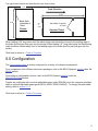
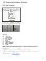
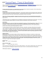
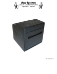
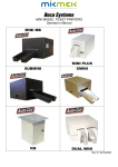
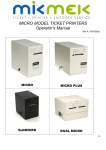
LEMUR TICKET PRINTERS
Operator’s Manual
Lemur
Lemur-S
Lemur-2
Lemur-K
Lemur-2K
RevA: 12.04.09
Table of Contents
Page
FCC Notice & Warranty Information
2
1.0
Introduction
3
2.0
Unpacking the printer
3
3.0
Important Safety Information
4
4.0
Installation
5
5.0
Ticket Load Procedure
7
6.0
Configuration
8
7.0
Standard Interface Pinouts
9
8.0
Thermal Paper – Theory & Specifications
10
9.0
Maintenance and Adjustments
11
9.1
Paper Guide and Print Head Assembly
11
9.1.1
Cut or Tear Opto
12
9.1.2
Thermal Print Head
13
9.1.3
Platen
14
9.1.4
Ticket Width Adjustment
15
9.2
Cutter Assembly
16
9.3
Logic Board
17
9.3.1
Logic Board (Removal)
17
9.3.2
Logic Board (Installation)
18
9.4
General Cleaning
18
10.0
Spare Parts List
18
11.0
Troubleshooting Guide
22
Appendix A - CONTROL PANEL
24
Appendix B - VERTICAL PRINTER INSTALLATION
27
Appendix C – LEMUR-2 OR LEMUR-2K
28
Appendix D - CHANGING ETHERNET PARAMETERS
29
Appendix E – INTERFACE TESTING A LEMUR
30
Appendix F – DOWNLOADING SOFTWARE COMMANDS
34
Appendix G – CONFIGURE WI-FI CONNECTION
39
1
FCC NOTICE
NOTE: The equipment has been tested and found to comply with the limits for a class A digital
device, pursuant to part 15 of the FCC rules. These limits are designed to provide reasonable
protection against harmful interference when the equipment is operated in a commercial environment.
This equipment generates, uses, and can radiate radio frequency energy and, if not installed and
used in accordance with the instruction manual, may cause harmful interference to radio
communications. Operation of this equipment in a residential area is likely to cause harmful
interference in which case the user will be required to correct the interference at the user’s expense.
Operation is subject to the following two conditions:
1. This device may not cause harmful interference, and
2. This device must accept any interference received, including interference that may
cause undesired operation.
NOTE: This unit was tested with shielded cables on the peripheral devices. Shielded cables must be
used with the unit to insure compliance.
WARRANTY INFORMATION
BOCA warrants the equipment manufactured and sold by it to be free from defects in material and
workmanship under normal use and service for a specified period of time. Parts damaged by
negligence or misuse (bad ticket stock, improper operating conditions, etc.) are excluded from this
warranty. Warranties for printers are 1 year from date of shipment. (NOTE: The print head is a
consumable part and is warranted for 90 days.) Spare parts carry a 90 day warranty. Tickets are
warranted, under proper storage conditions, for a period of 3 years. All warranty work is to be
performed either by BOCA or by an authorized BOCA service center. Shipping charges to the repair
center are the customer's responsibility. BOCA will pay for the equipment's return via ground service.
Please go to the link below if you have any reported issues with your new BOCA printer.
www.bocasystems.com/onlinesupportform.html
Equipment damaged in shipping should be reported immediately both to BOCA and to the shipper.
EXTENDED WARRANTY PLAN - BOCA offers extended warranty plans for all printer models. These
plans cover all parts and labor. All labor is to be performed at the BOCA facility. Equipment
damaged by misuse or negligence, including damage to print heads caused by defective ticket stock,
is excluded from this extended warranty. The customer, at its option, may request BOCA to ship
individual parts to expedite simple repair procedures. In certain cases where the customer is unable
to wait for the normal repair cycle, BOCA will ship an exchange printer within one business day after
notification by the customer. All freight charges are the responsibility of the customer.
Click here to return to > Table of Contents
2
1.0 Introduction
The Lemur series printers are direct thermal ticket printers that may be purchased with optional integrated
cutting mechanism and LCD display. This manual will provide the user with general information regarding
printer set-up, configuration and troubleshooting. Please read the important safety information section before
installation is conducted. Review the programming guide for additional details.
2.0 Unpacking the Printer
The printer is shipped in a ruggedized container. Please save packing material for future use. Remove the
printer and accessories from the box and inspect for obvious damage. If damage is noticed, please report it
immediately to BOCA.
Email: [email protected]
Tel: (561) 998-9600 Fax: (561) 998-9609
The following items should be in the box:
a) Ticket Printer
b) Hopper (if applicable)
c) AC power cord
d) Interface cable (optional)
e) Mounting Plate (optional)
Plastic
Film Top
Plastic
Film Bottom
NOTE: When shipping, make sure plastic film is placed on the bottom and top of printer.
Click here to return to > Table of Contents
3
3.0 Important Safety Information
WARNING: The appearance of this symbol indicates the proximity of an
exposed high voltage area. Please follow all directions carefully for your
personal safety. You must read the following safety information carefully
before working on the printer.
As a safety precaution, all service to the printer should be done by qualified persons with
power off and the AC cord unplugged from the printer. Following any procedure requiring the
removal of covers and/or doors, please verify that they have been properly attached and
fastened prior to operating the printer.
WARNING: "Provide an earthing connection before the mains plug is connected to the mains. And, when disconnecting
the earthing connection, be sure to disconnect after pulling out the mains plug from the mains."
WARNING: Power Cord Set: This must be approved for the country where it is used:
U.S.A. and Canada
! The cord set must be UL-approved and CSA certified.
! The minimum specification for the flexible cord is:
! No. 18 AWG
! Type SV or SJ
! 3-conductor
! The cord set must have a rated current capacity of at least 10A.
! The attachment plug must be an earth-grounding type with a NEMA 5-15P (15A, 125V) or NEMA 6-15P (15A,
250V) configuration.
United Kingdom only
! The supply plug must comply with BS1363 (3-pin 13 amp) and be fitted with a 5A fuse which complies with
BS1362.
! The mains cord must be <HAR> or <BASEC> marked and be of type H03VVF3GO.75 (minimum).
Europe only:
! The supply plug must comply with CEE 7/7 (“SCHUKO”).
! The mains cord must be <HAR> or <BASEC> marked and be of type H03VVF3GO.75 (minimum).
Denmark: The supply plug must comply with section 107-2-D1, standard DK2-1a or DK2-5a.
Switzerland: The supply plug must comply with SEV/ASE 1011.
WARNING: The appliance coupler (the connector to the unit and not the wall plug) must have a configuration for mating
with an EN60320/IEC320 appliance inlet.
WARNING: The socket outlet must be near to the unit and easily accessible.
WARNING: France and Peru only:
This unit cannot be powered from IT† supplies. If your supplies are of IT type, this unit must be powered by 230V (2P+T)
via an isolation transformer ratio 1:1, with the secondary connection point labelled Neutral, connected directly to earth
(ground).
WARNING: RJ-45 Ports. These are shielded RJ-45 data sockets. They cannot be used as standard traditional telephone
sockets, or to connect the unit to a traditional PBX or public telephone network. Only connect RJ-45 data connectors.
Either shielded or unshielded data cables with shielded or unshielded jacks can be connected to these data sockets.
Click here to return to > Table of Contents
4
4.0 Installation
The Lemur series printer was designed to be mounted either on a desktop or shelf (horizontal model) or
vertically in a counter top (see Appendix B for installation of vertical printers).
Prior to site preparation and installation, the printer should be powered up and run in the self-test mode.
!
Lay the printer flat on a counter top. On a Lemur-S model printer you will need to remove the side
cover.
!
Attach the AC cord and interface cable into the proper connectors.
!
Install ticket hopper (if applicable) to catch the tickets. Lemur printer without a cutter won’t have a ticket
hopper.
!
Turn power on. The LCD will display PAPER OUT and the red Check Paper led will be illuminated.
You will hear the cutter motor cycle if the printer contains a cutter.
!
Begin loading tickets through the entrance slot with a smooth motion until the printer automatically
positions the ticket. See section 5.0 Ticket Load Procedure.
NOTE: You want to make sure that the black timing mark is in the correct location before loading the tickets
into the paper path. See www.bocasystems.com/tickets_specs.html for black mark layout specs.
!
After the ticket is automatically positioned (the green READY led will be illuminated), press the TEST
button located on the control panel to print a test ticket. The next page shows sample self test ticket
printouts.
!
Verify that the printer properly works with your system by issuing a ticket through your computer
system. You may also use out customer based program to test the printer independently of your
ticketing system (see Appendix E)
You may now install the printer in its permanent location. Adequate room should be provided behind the
printer for the smooth feeding of ticket stock. Please do not prevent the ticket hopper (horizontal models) from
operating by touching tickets during the printing cycle.
5
Above sample was printed on a 4”x6” ticket using a 300dpi Lemur without cutter.
Above sample was printed on a 2” x 5.5” ticket using a 200dpi Lemur with cutter.
Your printout may vary depending on printer configuration and ticket stock used.
Click here to return to > Table of Contents
6
5.0 Ticket Load Procedure
Turn the printer on and wait five seconds. The red CHECK PAPER led will be illuminated (if your printer has
an optional LCD then it will display PAPER OUT). Begin loading the tickets through the entrance slot with a
smooth motion until the ticket stock comes to a stop (at this point the stock is between the thermal head and
platen). Keep pressure against the stock and the printer will automatically feed the ticket stock.
NOTE: see Appendix C for loading of Lemur-2 and Lemur-2K printers.
Load your stock towards this
side and below this metal plate
The black timing mark on the back of
your ticket stock should past over this
side facing down towards the opto
Reverse Adjustable (RADJW & RADJ4)
Load your stock towards this
side and below this metal plate
The black timing mark on the back of your
ticket stock should past over this side facing
down towards the opto
Adjustable (ADJ, ADJW & ADJ2)
Above two photos are of a Lemur and Lemur-K printer. The ticket feed area of a Lemur-2 and Lemur-2K would
look the same.
Above photo is of a Lemur-S with optional cutter. Your printer may vary.
7
Two typical ticket formats and feed directions are shown below.
2.0”
Feed Direction
5.50”
3.25”
Black Mark
Underside of
Ticket
2.0”
or
3.25”
Cinema
Black Mark Underside
of Ticket
Standard Ticket
When loading 5.50” long ticket stock the black timing mark should be closest to the leading edge of
the ticket (the first part that goes into the printer).When loading 2.0”” long ticket stock the black timing
mark should be furthest away from to the leading edge of the ticket (the first part that goes into the
printer).
Click here to return to > Table of Contents
6.0 Configuration
The Lemur series printer is factory configured for a variety of customer requirements.
For a comparison of the different electronics packages, refer to the BOCA Systems website under the
BASIC section.
For a listing of configuration choices, refer to the BOCA Systems website under the
SPECIFICATIONS section.
Printers are configured with a reverse adjustable paper guide (RADJW) set to the customer specified
width or optional adjustable paper guide (ADJ4, ADJW, ADJ2 & RADJ4). To change the ticket width
setting, refer to section 9.1.4.
Click here to return to > Table of Contents
8
7.0 Standard Interface Pinouts
RJ12 Serial Connection
+5VDC
RJ12 Connector
TYPICAL DB9 to RJ12 PIN CONNECTIONS
9 pin host BOCA RJ12
2
2
3
3
5
4
6
1
8
6
Transmit
Receive
GND
RDY
CTS
PARALLEL
PIN FUNCTION
1
Strobe (negative)
2-9
Data (DB0 - DB7)
10
ACK (negative)
11
BUSY
12
PAPER OUT
13
SELECT (negative)
15
ERROR (negative)
18
Ground
USB is considered a full speed device (version 1.1) not a high speed device (version 2.0).
ETHERNET (Optional) is a standard RJ45 Ethernet cable connection.
NOTE: The above pinouts may vary on certain printers due to special customer request.
Click here to return to > Table of Contents
9
8.0 Thermal Paper - Theory & Specification
Refer to the BOCA Systems website at www.bocasystems.com, THERMAL TICKETS section for the
most current paper specifications.
The print head’s life expectancy is composed of both a mechanical and an electrical component. Both of these factors
are strongly influenced by the quality of the thermal paper used.
MECHANICAL
The print head has a theoretical rating of 60 kilometers. This number is based upon the assumption that the head will be
used with a good quality, top coated thermal paper. Uncoated and poorly top coated thermal papers are abrasive to the
print head and have been found to wear through the head after less than one kilometer.
Other factors which may contribute to premature mechanical wear are the use of non-thermal inks and stray metallic
particles stuck in ticket perforations. Certain inks colors such as opaque white (which contains titanium dioxide) are also
highly abrasive.
Unfortunately, there are no available devices for quantitatively measuring the abrasiveness of a given ticket. Fortunately,
we have developed a slightly subjective, but effective method of weeding out overly abrasive ticket stock.
ELECTRICAL
Each heat element, dot, on the print head has a theoretical life expectancy of 100 million activations. This is based on the
assumption that each activation will cause the dot temperature to approach the dot’s maximum recommended
temperature. Running at lower temperatures will increase the theoretical life expectancy, while slight temperature
increases will seriously (exponentially) degrade the head life.
The thermal paper can affect the electrical head life in two ways. Insensitive, slow papers will typically encourage the
user to increase the voltage to darken the printed image. This will directly increase the head temperature resulting in
reduced head life. Additionally, the higher temperatures will frequently cause the ink to peel off the ticket and deposit onto
the print head. The ink debris will disrupt the normal transfer of heat from the head to the paper. This further increases
the head temperature above the desired level. The use of non-thermal inks and/or non-top coated papers also will cause
the ink to release and deposit on the print head.
SPECIFICATION
Based upon the above technical information, BOCA has always tried to encourage our customers to use the proper
thermal papers to maximize the life of their print heads. BOCA provides an extensive series of papers which meet the
above criteria for low abrasion and high sensitivity. We have also tested and approved a number of Ricoh thermal papers
which meet our criteria. While we have not had the opportunity to test other manufacturers’ thermal papers, we feel
confident that other papers manufactured with the above goals in mind should be acceptable for use in our printers. The
following list of papers have been approved by BOCA.
200 dpi usage
BOCA
T4, T5, T7, LCS and SKI10
200 and 300 dpi usage
BOCA
HS7, M7, HS5, HS11, KEY10
Please note that the 300 dpi papers may be used on 200 dpi printers. In fact, doing so will allow the user to decrease the
head energy thereby increasing the electrical life of the head. DO NOT use 300 dpi heads with 200 dpi paper.
Click here to return to > Table of Contents
10
9.0 Maintenance and Adjustments
Your ticket printer is solidly constructed and has been designed for high volume use. It requires minimal care
to provide maximum service.
WARNING: The appearance of this symbol indicates the proximity of an
exposed high voltage area. Please follow all directions carefully for your
personal safety. You must read the following safety information carefully
before working on the printer.
This section provides an overview of printer maintenance, including part alignments, adjustment and replacement.
For discussion purposes, the printer consists of three major modules or assemblies:
• Paper guide and print head assembly
• Cutter assembly
• Logic board assembly
As a safety precaution, all service to the printer should be done by qualified persons with
power off and the AC cord unplugged from the printer. Following any procedure requiring the
removal of covers and/or doors, please verify that they have been properly attached and
fastened prior to operating the printer.
9.1 Paper Guide and Print Head Assembly
The principal function of this assembly is to guide the ticket stock to the thermal print head where thermal
printing takes place. Additionally, this assembly houses the drive platen and ticket positioning sensors. If
necessary, the total assembly may be removed from the unit. All replacements and adjustments of the
components on this assembly may be done without removing the total assembly. The most common
adjustments and replacements regarding this assembly follow:
Click here to return to > Table of Contents
11
9.1.1 Cut or Tear Opto
There is one optical sensor (opto) mounted on an adjustable aluminum bracket. The opto controls
the cut or tear position. Removal or adjustment of the opto should be done without removing the
bracket from the paper guide. The opto position is factory set and adjustment should not be
necessary.
Note: Before making any opto adjustments make sure your ticket stock was manufactured to proper
ticket specifications.
To adjust the cut or tear position, physically adjust the opto mounting bracket forward or backwards to
achieve the desired cut or tear location. On a Lemur with auto cut the cut position should be a 1/16”1/8” away from the ticket perforation. On a Lemur without auto cut the ticket perforation should line
up with the edge of the cabinet or top plate.
Cut or tear position may also be adjusted via the control panel (if applicable) by changing the
INC/DEC CUT1/2 settings. (See Appendix A)
If you are not able to get the desired cut position, make sure your ticket stock was manufactured to
proper specifications.
Once a year the optos eyes should be blown off with air. This interval will vary depending upon the
environment and the quality of the ticket stock.
Click here to return to > Table of Contents
12
9.1.2 THERMAL PRINT HEAD
The print head should be cleaned periodically to prevent debris from building up on the print element. The
required cleaning interval varies greatly depending on the quality of the ticket stock and the amount of dust
entering the print area. Excessive dirt build up on the print head will result in reduced quality. Continuing to
run the print head in a dirty condition will reduce its life expectancy, as it is unable to diffuse its heat properly.
The thermal print head can be removed for cleaning or replacement, as follows:
1. Make sure power is off and the AC cord is disconnected from the printer.
2. DO NOT UNPLUG CABLE FROM PRINT HEAD.
3. Lift up on the cam lock assembly (located above the head mounting block or plate) to
remove pressure from the thermal head. Photo A
4. Lift up on the head mounting plate/thermal head to remove. Photo B
5. Clean the thermal print head surface (the side that makes contact with the paper)
with isopropyl alcohol. Photo C
6. Install the head by reversing the above procedures.
7. Restore pressure to the head by pushing down on the cam lock assembly.
8. The printer in now ready for operation. If the print quality is still poor then the
thermal head needs to be replaced.
9. To replace print head remove ribbon connector from print head and then remove
print head from mounting plate by removing two Philip head screws.
Cam Lock
Lever
Head mtg.
Plate
Photo A
Photo B
Clean This Surface
Photo C
13
9.1.3 Platen (Rubber Driver Roller)
The Platen (rubber drive roller) should be cleaned once a year to prevent paper dust from building up on the
roller. (NOTE: The platen may require more frequent cleaning in dusty environments or when using inferior
ticket stock.)
1. Make sure power is off and the AC cord is disconnected from the printer
2. Unlock the cam lock lever and remove head mounting block/ plate. (Refer to section 9.1.2 Thermal Print
Head)
3. Apply a small amount of Isopropyl alcohol onto a paper towel to clean the rubber roller.
4. Clean only the part of the rubber roller where the ticket stock makes contact with.
5. Rotate the rubber roller clockwise a little and repeat step 4; continue in the same manner for
one full revolution of the rubber roller.
6. Install the head mounting block/ plate and lock the cam lock lever back in place. Printer in now
ready for normal operation.
Platen
Platen size may very from what is shown in the photo.
Click here to return to > Table of Contents
14
9.1.4 Ticket Width Adjustment
To adjust the paper path for use with a different ticket width, adjust the slider bar to the fully open position.
Insert your ticket stock into the paper guide. Adjust the slider bar down to the proper ticket width, making sure
the bar is not too tight against the ticket. The ticket should move freely in the paper guide.
Slider Bar
The slider bar would be
located here for 3.25”
ticket width
Ticket Stock
Load your stock towards this
side and below this metal plate
Above photo is of a RDJW paper path set for 2” wide stock
On reverse adjustable printers (RADJW or RADJ4), the “special head” setting via the control panel must be
changed to match the new ticket width (see Appendix A). If the printer doesn’t have the optional control panel
then the width adjustment can be made via a software command (see Appendix F).
Load your stock towards this
side and below this metal plate
Ticket Stock
Slider Bar
Above photo is of ADJ paper path set for 4” wide stock
No control panel adjustment is necessary on standard adjustable printers (ADJ, ADJW or ADJ2).
Click here to return to > Table of Contents
15
9.2 Cutter Assembly
The BOCA cutter system is a fully integrated cutter knife mechanism powered by a stepper motor.
The cutter requires no adjustments and is rated for approximately 750,000 cuts. Please be aware of
the following:
Wait five seconds before feeding ticket stock into the printer after power up. During this time the
cutter knife will move up and down. If ticket stock is fed into the printer before five seconds, a ticket
jam could occur.
The cutter area should be blown out with air periodically to prevent debris from building up inside the
cutter area. The required cleaning interval varies greatly depending on the quality of the ticket stock
and the amount of paper dust entering the cutter area.
If the printer will be used with ticket stock that has a thickness greater than .008” then the cutter
speed needs to be changed to SLOW. Please contact BOCA for documentation to make this change.
If the cutter speed is not changed to SLOW, then the printer will not work reliably with said stock.
Boca Cutter
Click here to return to > Table of Contents
16
9.3 Logic Board
The printed circuit boards used in this product have been manufactured using surface mount
technology. These printed circuit boards cannot be effectively repaired in the field and should be
returned to the manufacturer if repair is required.
Warning: ALL SERVICE SHOULD BE DONE WITH POWER OFF AND THE AC CORD
UNPLUGGED FROM THE PRINTER.
See below pictures for main logic board access: (Click on image for larger picture)
Lemur & Lemur-K
(Electronics cover removed)
Lemur-S
(Rear access panel removed)
Lemur-2 & Lemur-2K
(Electronics cover removed)
9.3.1 Logic Board (Removal)
1. Gain access to the logic board. This is normally done by removing the electronics cover or rear
access panel (for Lemur-S).
2. Denote where all the cable plug into the logic board.
3. Unplug connectors connected to the main logic board.
4. Remove the four 3/16” head screws that secure the logic board onto the cabinet.
5. Lift board and remove.
Click here to return to > Table of Contents
17
9.3.2 Logic Board (Installation)
1. Installed the logic board into the printer.
2. Install the four 3/16” head screws that hold the logic board onto the cabinet and tighten.
3. Attach connectors going to the main logic board.
4. Install the electronics cover or rear access panel.
9.4 General Cleaning
The interior of the printer should be cleaned whenever there is a visible accumulation of dust. Use a small
vacuum for cleaning. Be careful not to jar any of the printer’s parts loose.
10.0 Spare Parts List
#
1
2
3
4
5*
5
6*
6
7
8
8*
9*
10
11
12
12*
13
13*
14
14*
15
16
16*
17
18
18*
18*
18*
19
20
21
22
23
24
25
26
27
28
29
30
31
32
33
34
35
*
*
*
*
*
*
*
Part Number
422557-25
420881Z-1
423552-L
423759
P50-1003
P50-1017
P51-1011
P51-1007
P51-1014
423480Z
423480Z-VL
423485-VL
423192
423793
422888-115
42288-230
FGLZ46
FGLZ46-E
P46-110
P46-220
423764
423760-L3B-1
423760-L4B-1
423789
2003
3003
2004
3004
423496
422590
P28-1020
AC161A5
423236-2
5316H
421932-DSP
423559Z
422521
423565
P62-1006
422521Z
423792
423790
423791
423767
P45-1009
420881Z-2
420881Z-Plus
4208812Dual-2
4208812Dual-2
421623
422113
421623-5M4
Qty
1
1
1
2
1
1
1
1
1
1
1
1
1
1
1
1
1
1
1
1
1
1
1
1
1
1
1
1
1
1
1
1
1
1
1
1
1
1
1
1
2
1
1
1
1
1
1
1
1
1
1
1
Description
Cable Ribbon, Thermal Head
Cover Front, Lemur
Cutter Assembly
Display Holder
Drive Belt, 102T (for 300dpi)
Drive Belt, 98T (for 200dpi)
Drive Pulley, 30T (for 300dpi)
Drive Pulley, 20T (for 200dpi)
Drive Pulley, 20T (for 200dpi & 300dpi)
Upper Exit Deflector
Upper Exit Deflector (vertical mount Lemur only)
Lower Exit Deflector (vertical mount Lemur only)
Ground Strap
Energy Star Decal
Transformer (110VAC)
Transformer (230VAC)
Main Logic Board (Standard)
Main Logic Board (Ethernet option)
Power board, 110VAC
Power board, 220VAC
Opto Detector Assembly (opto)
Platen (RADJW, ADJ2 & ADJW)
Platen (ADJ4 & RADJ4)
AC Filter
Print Head (200dpi RADJW, ADJ2 or ADJW)
Print Head (300dpi RADJW, ADJ2 or ADJW)
Print Head (200dpi ADJ4 & RADJ4)
Print Head (300dpi ADJ4 & RADJ4)
Head Mounting Plate
Stepper Motor
Switch, Ticket Load
LCD Display
Take Out Head Cam Lock
Control Panel Decal
Fill-in Plate, Display
RFI Cutter Shield
Electronics Box, Lemur & Lemur-K
Dust Cover, Cutter
Anti Static Brush
Electronics Box, Lemur-2 & Lemur-2K
Shoulder Bearing, Platen
DC Out Cable, Power Board
AC Out Cable, Power Board
UL Cover, Power Board
Bearing (Large)
Cover, Lemur
Cover, Lemur-S
Cover, Lemur-2
Cover Front, Lemur-2
Hopper, 2” wide ticket stock (cutter Lemur-S)
Hopper, 2” wide ticket stock (cutter Lemur & Lemur-2)
Hopper, 2.5” to 4” wide ticket (cutter Lemur, Lemur-S & Lemur-2)
*Customer dependent and not shown in photos
18
8
20
7
2
5
6
21
15
3
11
22
24
Above and below photos are of a Lemur with optional LCD display and cutter
12
1
14
17
27
13
4
22
19
35
31
1
23
16
18
10
19
31
View with thermal head
unlocked and open.
35
20
8
7
5
6
15
21
3
26
View with cover removed.
Lemur-S with optional cutter
20
22
4
13
1
3
32
14
34
12
17
View with rear access
panel removed.
Lemur-S with optional cutter
20
20
1
1
23
23
28
29
28
3
3
29
Lemur-2K with optional cutters
21
1
12
1
33
14
13
30
25
Lemur-2 without optional LCD display
11.0 Troubleshooting Guide
This is a simplified troubleshooting guide listing some of the typical problems. It is not intended to provide
technical details or repair methods, but can serve as a guide to fault isolation in the field. As a safety
precaution, all service to the printer should be done by qualified persons with power off and
the AC cord unplugged from the printer. Following any procedure requiring the removal of
covers and/or doors, please verify that they have been properly attached and fastened prior to
operating the printer. If you need additional help, please visit the link below
www.bocasystems.com/onlinesupportform.html
1.
NO OPERATION, LED’S DON’T LIGHT UP UPON POWER UP
a. Power the printer off and wait 30 seconds then power it back on.
b. Check the power cord for proper installation at both ends.
c Check that there is power at the AC outlet.
d. Contact your system provider or BOCA for further assistance.
2.
POWER IS ON BUT NO OPERATION
a. Check to make sure the load switch (see item #21 of parts list) makes a clicking sound when you
load ticket stock over it. If switch needs adjustment then contact BOCA for documentation.
b. If cutter knife (if so equipped) does not go up and down after power up, See # 6.
c. With the printer powered off, unplug the thermal head and turn on the printer. If printer works then
replace the thermal head.
d. Contact your system provider or BOCA for further assistance.
3.
POWER IS ON BUT TICKET WILL NOT LOAD
a. See # 2
b. Make sure the print head/cam lock assembly is fully locked in the closed position.
Consult “Thermal Print Head” section.
22
c. Check that the ticket stock is being loaded correctly. Consult “Installation” section.
d. Contact your system provider or BOCA for further assistance.
4.
ERRATIC CUT POSITION
a. Check for defective ticket stock. Is the black mark unevenly spaced apart or
light in color? Is the ticket too wide for the paper path?
b. Clean off opto eyes (see item #15 of parts list) with air.
c. Check that the platen is clean. Consult “Platen (Rubber Drive Roller)” section.
d. Replace ticket cut opto.
e. Contact your system provider or BOCA for further assistance.
5.
ERRACTIC PRINT POSITION
a. See # 4
6.
CUTTER KNIFE DOES NOT MOVE (if equipped)
a. Check for blockage in the cutter area.
c. Default printer settings. With the printer powered off hold down the TEST button and then power up
the printer. Keep the TEST button held down for ten seconds and release.
c. Contact your system provider or BOCA for further assistance.
7.
POOR PRINT OUT (light print out)
a. Try a different stack of ticket stock.
b. Make sure the print head/cam lock assembly if fully locked in the closed position.
c. Clean print head. Consult “Thermal Print Head” section.
d. Adjust print intensity setting via the control panel (if equipped). (see Appendix A)
e. Replace thermal head.
f. Contact your system provider or BOCA for further assistance.
8.
POOR PRINT OUT (white voids in print out)
a. Clean print head. Consult “Thermal Print Head” section.
b. Replace thermal head.
c. Contact your system provider or BOCA for further assistance.
9.
NO PRINT OUT
a. Try a different stack of ticket stock.
b. Check head cable for electrical connection at both ends
c. Check to make sure head cable is plugged in properly into the thermal head.
d. Replace the thermal head.
e. Contact your system provider or BOCA for further assistance.
10.
PRINTER SKIPS TICKETS WHILE PRINTING
a. Check position and quality of black mark on the ticket stock.
b. Clean off opto eyes with air.
c. Check that the platen is clean. Consult “Platen (Rubber Drive Roller)” section.
c. Replace ticket cut opto.
d. Contact your system provider or BOCA for further assistance.
11.
PRINTER SKIPS TICKETS AND DIES
a. See # 10.
12.
TICKET JAM ENTERING THE CUTTER AREA
a. Make sure the entrance to the cutter area is not blocked.
b. Contact your system provider or BOCA for further assistance.
Click here to return to > Table of Contents
23
APPENDIX A - CONTROL PANEL
The FGL46 printers allow the user to adjust various printer options through the optional control panel. To access the
control panel menu, press both MENU and TEST switches simultaneously for about 3 seconds. The LCD will display the
“OPERATOR MENU!” message to indicate that it has entered the control panel menu mode. Once in this mode, please
use the following steps in the manner indicated to choose the proper menu topic and to select the proper setting.
Enters new value. Also
saves new values
Scrolls through choices in
individual menu topics
Selects proper menu topic
(baud rate, cut count, etc.)
To access and use the OPERATOR MENU, follow these steps:
1. Ticket stock should be loaded into the printer. The LCD window displays FGL46G# - SB# (# - number value
depends on revision level; G represents the software series level; B# is the font)
2. Press both MENU and TEST switches simultaneously for about 3 seconds. The LCD window displays OPERATOR
MENU. (To access the factory menu, press MENU and CHOICES instead of MENU and TEST.) WARNING:
Improper use of the factory menu may disable your printer.
3. To scroll through the menu topic, use MENU stopping on the topic you wish to change.
4. Press CHOICES to scroll through choices in the selected topic. NOTE: The printer displays a blinking cursor for the
values presently stored in the printer.
5. Once you have found the new value you want, press TEST. The LCD window displays EXIT AND SAVE?. If you
wish to save the new value then press TEST again.
6. If you do not wish to save the new value then press MENU. The LCD window displays JUST EXIT?. Press
TEST to exit the OPERATOR MENU without saving new values or press MENU to enter back into the
OPERATOR MENU.
The chart below lists the present menu topics. These topics are subject to change.
OPERATOR MENU
BAUD RATE?
MINI/MICRO?
PRINT SPEED?
DIAGNOSTIC MODE?
STATUS ENABLED?
TRANSPARENT MODE?
PAPER MODE?
SPECIAL HEAD
CLEAR DOWNLOAD
INC CUT1 COUNT?
DEC CUT1 COUNT?
INC CUT2 COUNT?
DEC CUT1 COUNT?
PRINT MODE?
PRINT INTENSITY?
TEST TICKET?
ETHERNET?
IP ADDRESS?
SUBNET MASK?
DEFAULT GATEWAY?
SPEED/DUPLEX?
EXIT AND SAVE?
JUST EXIT
24
The following is a brief overview of some representative Menu options:
BAUD RATE? Controls the serial interface baud rate, parity bit, data bits and stop bits.
Here are the following choices:
1200,N,8,1
4800,N,8,1
19200,N,8,1
1200,E,7,1
1200,O,7,1
2400,N,8,1
2400,E,7,1
2400,O,7,1
4800,E,7,1
4800,O,7,1
9600,N,8,1
9600,E,7,1
9600,0,7,1
19200,E,7,1
19200,0,7,1
28800,N,8,1
28800,E,7,1
38400,N,8,1
38400,E,7,1
57600,N,8,1
57600,E,7,1
115200,N,8,1
115200,E,7,1
MINI/MICRO? Defines the type of printer.
MINI
Is for a printer with a Silent Cutter Assembly (SC2) (Mini, Mini Plus, Mini MB, Dual Mini)
MICRO Is for a printer without a SC2 (Micro, Micro Plus, Micro MB, Dual Micro)
PRINT SPEED? Controls the speed the ticket travels at. Also effects the print quality.
The numbers range from 0 - FASTEST to 7 - SLOWEST. 3 is factory default.
DIAGNOSTIC MODE? Your choices are YES or NO. NO is factory default. (Please consult your Programming Guide)
TICKET TYPE? Factory setting. Do not modify.
STATUS ENABLED? Sets status response protocols.
Disables the XON/XOFF and status response protocols
NONE
Enables the XON/XOFF and status response protocol for the serial port.
SERIAL
Enables bi-directional parallel status responses if printer is configured as bi-directional.
PARALLEL
Enables both bi-directional parallel and serial status responses.
SER/PAR
Enables USB status responses
USB
Enables USB and serial status responses
USB/SER
Enables USB and bi-directional parallel
USB/PAR
Enables USB, bi-directional parallel and serial status responses
USB/SER/PAR
TRANSPARENT MODE? YES (Enabled) or NO (Disabled). (Please consult your Programming Guide)
PAPER MODE? Is generally used only for test purposes. It may also be used on roll stock with no black marks on the ticket. Your
choices are YES (Enabled) or NO (Disabled). NO is factory default.
SPECIAL HEAD? Is used when a special paper path size is installed (2.125”, 2.5”, 2.7”….)
Here are the following choices: This feature is set at the factory.
NO
ON P1
ON P2
ON BOTH
REV ADJ2 P1
REV ADJ2 P2
REV ADJ2 BOTH
REV ADJ2.5 P1
REV ADJ2.5 P2
REV ADJ2.5 BOTH
REV ADJ2.7 P1
REV ADJ2.7 P2
REV ADJ2.7 BOTH
REV ADJ3 P1
REV ADJ3 P2
REV ADJ3 BOTH
REV ADJ2.125 P1
REV ADJ2.125 P2
REV ADJ2.125 BOTH
REV ADJ3.25 P1
REV ADJ3.25 P2
REV ADJ3.25 BOTH
DUAL & SINGLE PATH PRINTER WITH RADW paper guide set to 3.25” & RADJ4 paper guide set to 4”
DUAL & SINGLE PATH PRINTER ONLY (Not used for a Lemur model printer)
DUAL PATH PRINTER ONLY on path #2 (Not used for a Lemur model printer)
DUAL PATH PRINTER ONLY on both paths (Not used for a Lemur model printer)
DUAL & SINGLE PATH PRINTER WITH RADW or RDJW4 paper guide set to 2”
DUAL PATH PRINTER WITH RADW or RDJW4 paper guide set to 2” on path #2
DUAL PATH PRINTER WITH RADW or RDJW4 paper guide set to 2” on both paths
DUAL & SINGLE PATH PRINTER WITH RADW or RDJW4 paper guide set to 2.50”
DUAL PATH PRINTER WITH RADW or RDJW4 paper guide set to 2.50” on path #2
DUAL PATH PRINTER WITH REV RADW or RDJW4 paper guide set to 2.50” on both paths
DUAL & SINGLE PATH PRINTER WITH RADW or RDJW4 paper guide set to 2.70”
DUAL PATH PRINTER WITH RADW or RDJW4 paper guide set to 2.70” on path #2
DUAL PATH PRINTER WITH RADW or RDJW4 paper guide set to 2.70” on both paths
DUAL & SINGLE PATH PRINTER WITH RADW or RDJW4 paper guide set to 3”
DUAL PATH PRINTER WITH RADW or RDJW4 paper guide set to 3” on path #2
DUAL PATH PRINTER WITH RADW or RDJW4 paper guide set to 3” on both paths
DUAL & SINGLE PATH PRINTER WITH RADW or RDJW4 paper guide set to 2.125”
DUAL PATH PRINTER WITH RADW or RDJW4 paper guide set to 2.125” on path #2
DUAL PATH PRINTER WITH RADW or RDJW4 paper guide set to 2.125” on both paths
DUAL & SINGLE PATH PRINTER WITH RADJ4 ONLY paper guide set to 3.25”
DUAL & SINGLE PATH PRINTER WITH RADJ4 ONLY paper guide set to 3.25” on path #2
DUAL & SINGLE PATH PRINTER WITH RADJ4 ONLY paper guide set to 3.25” on both paths
CLEAR DOWNLOAD? Clears those items downloaded by the operator to Flash memory.
Your choices are YES or NO.
25
INC CUT1/2 COUNT? moves the cut/tear position to the left (towards the ticket entrance area). Cut counts are increments of .003” for
300dpi and .005” for 200dpi. Depressing CHOICES changes the count value. 16 is factory default. (1 is for path one; 2 is for path 2
[dual only])
DEC CUT1/2 COUNT? moves the cut/tear position to the right (towards the ticket exit area). Cut counts are decrements of .003” for
300dpi and .005” for 200dpi. Depressing CHOICES changes the count value. 16 is factory default.
PRINT MODE? Defines the automatic ticket length calculation feature.
THERMAL The printer will feed out and then retract a ticket during this measurement.
RIBBON The printer will feed out one blank ticket. This mode is used for label stock to prevent peeling.
PRINT INTENSITY? Controls the darkness of ticket print out.
Here are the following choices:
LIGHT
MED LIGHT
NORMAL
MED DARK
SHORT HEAD LIFE
(factory default)
TEST TICKET? Defines they type of self-test ticket printed.
STANDARD
Normal self test ticket pattern (factory default)
To print configuration settings if printing on a 1” wide ticket
CONFIGURATION 1
To print configuration settings if printing on a 2” wide ticket
CONFIGURATION 2
To print configuration settings if printing on a 3” wide ticket
CONFIGURATION 3
To print configuration settings if printing on a 4” wide ticket
CONFIGURATION 4
ETHERNET? Only used for printer with Ethernet interface connector.
Ethernet not enabled.
NO
Uses the IP address that has been set in the printer by the customer.
YES
This feature should not be used.
Diagonstics
This feature should not be used.
Valid Packets
Automatically attempts to get an IP address from Local Server
DHCP Enabled
Automatically attempts to get an IP address/Subnet Mask/Gateway from Local Server
DHCP/SUB/GATE
Automatically attempts to get an IP address from Local Server and then register the name with the
DHCP/NR
local NetBIOS name server – usually the WINS Server
Automatically attempts to get an IP address/Subnet Mask/Gateway from Local Server and then
DHCP/SUB/GATE/NR
register the name with the local NetBIOS name server – usually the WINS Server
IP ADDRESS? Enables the operator to change the printer’s Ethernet IP Address. (See Appendix D )
SUBNET MASK? Enables the operator to change the printer’s Ethernet Subnet Mask value. (See Appendix D )
DEFAULT GATEWAY? Enables the operator to change the printer’s Ethernet default Gateway value. (See Appendix D )
Programming Guide.
SPEED/DUPLEX? Enables the operator to change the printer’s Ethernet speed and duplex setting. Please consult FGL Programming
Guide. Your choices are AUTO-NEGOTIATE, 100Mbps/FULL, 100Mbps/HALF, 10Mbps/FULL and 10Mbps/HALF.
EXIT AND SAVE ! Will save any changes made to the above menu options.
If you wish to save the new value then press TEST, if not press MENU.
JUST EXIT? Will exit the menu options without saving any changes.
If you with to exit without saving the new value then press TEST, if not press MENU.
Click here to return to > Table of Contents
26
APPENDIX B - VERTICAL PRINTER INSTALLATION
Prepare the counter top by cutting a rectangular hole in accordance with the dimensions specified for your
printer model. NOTE: The table or counter top must be able to support at least four times the weight of
the printer.
Vertical Mount Lemur
Vertical Mount Lemur-2
!
!
!
!
!
Attach the top plate to the printer using only the supplied mounting hardware.
Insert the printer with the top plate attached into the countertop cutout.
Attach the power cord and the interface cable to the printer.
Turn the power switch to the ON position.
The printer is now ready for ticket stock to be loaded.
Click here to return to > Table of Contents
27
APPENDIX C – LEMUR-2 OR LEMUR-2K
Ticket Load Procedure for a Lemur-2 Printer
Feed Direction
Path 2
Path 1
Your printer may vary from the above photo
Turn the printer on and wait five seconds. If your printer has an optional LCD then it will display
PAPER OUT (the red CHECK PAPER led will be illuminated). Begin loading the tickets through the
entrance slot of path #1 with a smooth motion until it stops. At this point the printer should
automatically grad and positions the ticket. Once path #1 had been loaded, you then can load path
#2 the same way. Both paths need to be loaded in order for the printer to work properly.
Section 5.0 Ticket Load Procedure will provide information on how the stock should be loaded into
the entrance slots.
After the ticket is automatically positioned (the READY LED will be illuminated), press the TEST
button located on the control panel to print a test ticket. The first ticket will print out on path #2 and
when you press the TEST button a second time the ticket will print out on path #1.
Which side the printer prints on is controlled by the data being sent from you host computer.
Click here to return to > Table of Contents
28
APPENDIX D – CHANGING ETHERNET PARAMETERS
CHANGING 'IP ADDRESS'
1. Please follow these steps to change the fixed IP address on your Ethernet printer. Note: if using a fixed
IP address make sure the ‘ETHERNET’ setting is set to ‘YES’ (see above).
2. Depress both the MENU and CHOICES buttons while turning on the printer. Keep both buttons
depressed until FACTORY MENU appears in the LCD window or the display starts scrolling through
different topics.
3. Using the MENU button scroll down to the IP ADDRESS? topic and press the CHOICE button.
4. The blinking cursor indicates the current IP numeric value selected. Every time you press the CHOICE
button the numeric value will change.
5. Using the TEST button will move you over to the next numeric value.
6. Continue steps 4 & 5 to program the desired IP address value.
7. At the end the display will show EXIT AND SAVE. Press the TEST button to save the IP address you
just entered.
CHANGING 'DEFAULT GATEWAY' ADDRESS
Follow same procedure as 'Changing IP address' above but in step 3 scrolls down to the DEFAULT
GATEWAY topic.
CHANGING 'SUBNET MASK' SETTING
1. Depress both the MENU and CHOICES buttons while turning on the printer. Keep both buttons
depressed until FACTORY MENU appears in the LCD window or the display starts scrolling through
different topics.
2. Using the MENU button scroll down to the Subnet Mask? topic and press the CHOICE button.
3. Each time you press the CHOICE button a different mask value will be displayed.
4. Once you have the mask value you want, press the TEST button. The display will show EXIT AND
SAVE. Press the TEST button a second time to save the address value.
Click here to return to > Table of Contents
29
APPENDIX E – INTERFACE TESTING A LEMUR
Boca Systems, Inc. has developed a program that allows customers to communicate from a host computer to
the printer over any interface (parallel, serial, USB, Ethernet) and print drivers too. The below programs are
found on our website under the “Ghostwriter News “section.
For PC use without printer drivers customer program is used with Parallel, Serial & Ethernet
interfaces.
For PC use with printer drivers customer program is used with print drivers.
You may download load the program that fits your needs. To use these programs you will need to download
the executable file to your Windows based host computer and run the setup program. The following steps will
guide you through using these programs on they have been installed on your host computer.
1. Hook the BOCA printer to the host computer that you have the Customer program loaded onto. Make
sure that the printer has stock loaded and it ready to go. A printer is ready to print when it is able to
print out a self test ticket by depressing the TEST button. If you are not able to get a self test ticket,
refer to the users manual to make sure you have the printer properly setup.
2. On your Window’s desktop click on the START icon and then click on PROGRAMS to see all your
computer’s programs.
3. Find “Boca Systems” and click on one of the below to start the program.
“Customer Interfaces” – If you are connecting through a Parallel, Serial or Ethernet port
“Customer Drivers” – If you are connecting via print driver. Proceed to step #5
4. Once the Customer Interfaces program is running, click on the “Select Printer Interface” drop-down
arrow. You will want to choose the interface connection that you have the BOCA printer hooked up to
then go to step #6.
5. Once the Customer Drivers program is running, click on the “Printer Drivers” drop-down arrow that is
found under Select A Printer. You will want to choose the driver you had downloaded for the BOCA
printer.
Your selection of drivers will vary from what is shown in above image
30
6. Now click on the “Select Printer Operation” drop-down arrow and chose the appropriate test program.
If your printer has FGL firmware then chooses “FGL Test Ticket” or if your printer had HP firmware
then choose “PCL Test Ticket”. If you are going to be sending a text commands then see Appendix F.
If you are going to configure your Wi-Fi connection then see Appendix G.
7. Once the Test Ticket selection box comes up, click on the OK button to print out a ticket. The printer
will print out an interface test ticket.
8. You may also print more than one ticket by repeating steps # 5 & 6 but this time change number of
tickets you want printed.
Above sample FGL ticket was printed on a 2” x 5.5” (concert) ticket using a RADJW-2” 200dpi FGL printer.
31
Above sample FGL ticket was printed on a 2” x 5.50” (concert) ticket using a RADJW-2” 300dpi FGL printer.
Above sample FGL ticket was printed on a 3.25” x 8” (receipt) ticket using a RADJW-3.25” 200dpi FGL printer.
Above sample FGL ticket was printed on a 3.25” x 8” (receipt) ticket using a RADJW-3.25” 300dpi FGL printer.
32
Above sample PCL ticket was printed on a 3.25” x 5” ticket using a RADJW-3.25” 300dpi PCL printer.
Click here to return to > Table of Contents
33
APPENDIX F – DOWNLOADING SOFTWARE COMMANDS
For those Lemurs model printers without LCD display the menu setting changes may be done by utilizing the
software commands listed below. This is best done using our customer based program (see Appendix E ).
If needed, the printer may be defaulted back to it’s originally factory settings as follows. With the printer
powered off hold down the TEST button and then power up the printer. Keep the TEST button held down for
10 seconds and release (the printer will reset at this time).
Once you have your interface or driver selected then click on the “Select Printer Operation” drop-down arrow
and choose “Enable FGL Commands (HP)”. When the FGL Command Enable box comes up, click the OK
button.
Now click on the same drop-down arrow you did in step #5 and chose “Send Text”. Once the Text Data box
comes up you type the text command in the Data input box. Then click on the OK button and the text data
will be sent to the printer.
34
The following list shows all of the commands necessary to access the operator control panel functions.
BAUD RATE COMMAND - <brx,y,z> (printer will reset after receipt of command)
Note: This function should only be used by an experienced user.
This command sets the baud rate (x), parity (y) and data bit size (z) for the printer. Valid values for each are
shown below. For example, to set a 9600 baud rate, even parity, 7 data bits send the <br9600,E,7> command.
x=
1200
28800
y = N (no parity)
z = 8 data bits*
2400
38400
E (even parity)
7 data bits
4800
57600
O (odd parity)
9600
115200
19200
MINI/MICRO COMMAND - <min>/<mic> (printer will reset after receipt of command)
This command sets the printer up as a Mini (cutter) <min> or Micro (no cutter) <mic>.
PRINT SPEED COMMAND - <ps#> (printer will reset after receipt of command)
This command sets the printing speed of the ticket. The values can range from 0-7. The slowest speed is 7.
The slower the speed the darker the printing.
DIAGNOSTIC MODE COMMAND - <DM>
This command is explained in the FGL programming guide.
STATUS ENABLED COMMAND - <se#>
This command enables or disables status responses from the printer to the Host. The values can range as
shown below:
0 - None (disabled)
1 - Serial
2 - Parallel
3 - Ser/Par
4 - USB
5 - USB/Ser
6 - USB/Par
7 - USB/Ser/Par
Note: Bi-directional parallel mode must be set first for Par options to be valid.
Note: USB mode must be set first for USB options to be valid.
TRANSPARENT MODE ENABLED/DISABLED COMMANDS - <tme>/<tmd>
These commands set the printer in transparent mode <tme> or non-transparent mode <tmd> after
initializing.
PAPER MODE ENABLED/DISABLED COMMANDS - <pme>/<pmd>
Note: This function is set at the factory and should not be changed.
These commands set the printer in paper mode <pme> or non-paper mode <pmd> after initializing.
SPECIAL HEAD SETTING COMMAND - <sph#> (printer will reset after receipt of command)
Note: This function is set at the factory and should not be changed.
This command sets the special head setting for the printer. The values can range from as shown below:
0 - no special head
1 - special head size path 1
2 - special head size path 2
3 - special head size both paths
RADJW set for 3.25” wide ticket
# Note: this is for non-reversible paper guide.
# Note: this is for non-reversible paper guide.
# Note: this is for non-reversible paper guide.
35
4 - reverse adjustable 2” path1
5 - reverse adjustable 2” path2
6 - reverse adjustable 2” both paths
7 - reverse adjustable 2.5” path1
8 - reverse adjustable 2.5” path2
9 - reverse adjustable 2.5” both paths
10 - reverse adjustable 2.7” path1
11 - reverse adjustable 2.7” path2
12 - reverse adjustable 2.7” both paths
13 - reverse adjustable 3.0” path1
14 - reverse adjustable 3.0” path2
15 - reverse adjustable 3.0” both paths
16 - reverse adjustable 2.125” path1
17 - reverse adjustable 2.125” path2
18 - reverse adjustable 2.125” both paths
19 – reverse adjustable 3.25” path 1
20 – reverse adjustable 3.25” path 2
21 - reverse adjustable 3.25” both paths
#Note: this is for RADJ4 ONLY paper guide
# Note: this is for RADJ4 ONLY paper guide
# Note: this is for RADJ4 ONLY paper guides
CLEAR DOWNLOAD SPACE COMMAND – ESC c
This command is explained in the FGL programming guide.
INC/DEC CUT1 COUNT COMMAND - <cca#> (printer will reset after receipt of command)
This command sets the cut count for path 1 (A). The value can usually vary from 0-30.
INC/DEC CUT2 COUNT COMMAND - <ccb#> (printer will reset after receipt of command)
This command sets the cut count for path 2 (B). The value can usually vary from 0-30.
PRINT MODE COMMANDS - <tml>/<rib>
Note: This function is set at the factory and generally should not be changed.
These commands set the printer up for Thermal <tml> or Ribbon (thermal transfer) <rib> printing.
PRINT INTENSITY COMMAND - <pi#>
Note: This function should only be used by an experienced user.
This command sets the print intensity setting for the printer. The values can range as shown below:
1 – light intensity
2 – medium light intensity
3 – normal intensity
4 – medium dark intensity
5 – short head life
TEST TICKET TYPE COMMANDS - <tst#>/<TST#>
These commands set the test ticket type that is printed off the test button. The values can range as shown
below:
0 – standard test ticket
1 – configuration 1 ( for 1 inch ticket)
2 – configuration 2 ( for 2 inch ticket)
3 – configuration 3 ( for 3 inch ticket)
4 – configuration 4 ( for 4 inch ticket)
6 – continuous test tickets
NOTE: The lowercase <tst#> commands sets the test ticket type in flash. The uppercase <TST#> command
sets the test ticket type until power is turned off. It will also print a test ticket without having to press the test
button.
36
ETHERNET MODE COMMAND - <eth#> (printer will reset after receipt of command)
This command sets the Ethernet mode for the printer and is permanently stored in flash. This can also be set
using the 'Factory Menu'. The values can range as shown below:
0 - NO - Ethernet Interface disabled
1 - YES - Ethernet Interface enabled (uses static IP address).
2 - Ethernet DIAGNOSTIC Mode - (prints all packets transmitted or received by the printer).
3 - Ethernet Diagnostic VALID PACKET Mode - (prints only valid packets transmitted or received by the
printer).
4 - DHCP ENABLED (automatically attempts to get an IP address from Local Server).
5 - DHCP/SUB/GATE (automatically attempts to get an IP address/Subnet Mask/Gateway from Local Server).
6 - DHCP/NR* (automatically attempts to get an IP address from Local Server and then register the name with
the local NetBIOS name server – usually the WINS Server).
7 - DHCP/SUB/GATE/NR* (automatically attempts to get an IP address/Subnet Mask/Gateway from Local
Server and then register the name with the local NetBIOS name server – usually the WINS Server ).
Notes: Ethernet Diagnostic Modes should only be used after consulting with Boca Systems.
The DHCP enabled function will cause the printer to automatically attempt to retrieve a ‘permanent’ IP address
from a Local Server after powering on. If the server does not assign a ‘permanent’ one, then it will allocate an
address for a limited period of time (lease time). If this is the case, the printer will automatically try and renew
its lease before it expires. If DHCP is enabled, but no response is received from a Local Server in time, the
printer will revert back to its default IP. For convenience, the printer’s IP address is now printed on the Test
Ticket.
PERMANENT PROTOCOL ADDRESS COMMAND - <ip10.0.1.25> (printer will reset after receipt of
command)
This command permanently changes the IP address of the printer and stores it in flash. The example above
would change the address to 10.0.1.25. The IP address can also be changed using the ‘Factory or Web
Menu’. The default address is 10.0.0.192. Note: IP address 0.0.0.0 is reserved.
PERMANENT SUBNET MASK COMMAND - <sub#> (printer will reset after receipt of command)
Note: This function should only be used by an experienced user.
This command permanently changes the Subnet Mask for the network and stores it in flash. The Subnet Mask
can also be changed using the ‘Factory or Web Menu’. The default mask is 0 (0.0.0.0). This is a reserved
value and is used by the printer to indicate there is no subnet. Thus the printer will treat all packets as if they
are on a ‘direct route’. If you want packets sent to the Gateway Address you must assign one of the following
non-zero values (1-32):
0
1
2
3
4
5
6
7
8
9
10
11
12
13
14
15
16
0.0.0.0 (reserved)
128.0.0.0 (class A)
192.0.0.0
“
224.0.0.0
“
240.0.0.0
“
248.0.0.0
“
252.0.0.0
“
254.0.0.0
“
255.0.0.0
“
255.128.0.0 (class B)
255.192.0.0 “
255.224.0.0 “
255.240.0.0 “
255.248.0.0 “
255.252.0.0 “
255.254.0.0 “
255.255.0.0
“
17
18
19
20
21
22
23
24
25
26
27
28
29
30
31
32
255.255.128.0 (class C)
255.255.192.0 “
255.255.224.0 “
255.255.240.0
“
255.255.248.0
“
255.255.252.0
“
255.255.254.0
“
255.255.255.0
“
255.255.255.128
255.255.255.192
255.255.255.224
255.255.255.240
255.255.255.248
255.255.255.252
255.255.255.254 (unusable)
255.255.255.255 (host-single address)
37
PERMANENT DEFAULT GATEWAY IP ADDRESS COMMAND - <dgw10.0.1.254> (printer will reset
after receipt of command). Note: This function should only be used by an experienced user.
This command permanently changes the IP address of the default gateway and stores it in flash. The example
above would change the address to 10.0.1.254. The Gateway Address can also be changed using the
‘Factory or Web Menu’. The default address is 10.0.0.192. Note: the subnet value must be non-zero in order
for the Gateway Address to be valid.
ETHERNET PORT CONFIGURATION - <epc#> (printer will reset after receipt of command)
Normally, the printer will auto-negotiate its port configuration with the network. Some customers have asked
for the ability to manually set the speed and duplex settings of the Ethernet port. This command permanently
stores the selected port settings in flash. The values (#) can range as shown below:
0 - Auto-negotiate
1 - 100 Mbps/Full duplex
2 - 100 Mbps/Half duplex
3 - 10 Mbps/Full duplex
4 - 10 Mbps/Half duplex
Click here to return to > Table of Contents
38
APPENDIX G – CONFIGURE WI-FI CONNECTION
To use the wireless capabilities of a printer equipped with the optional wireless interface (Wi-Fi), it will
first be necessary to setup the printer with information and security settings that match the settings of
the wireless server/router you are connecting to. To initially configure the wireless settings it will be
necessary to connect to the printer via the Parallel, RJ12, USB or Ethernet (if so equipped) interface.
We recommend using the Boca Systems Customer program to perform this task (see Appendix E).
After installing the Boca Systems Customer program, click on the “Update” button to acquire any
recent modifications to the tool. Once you have the program running click on the Help button in the
upper right hand corner. In the Select Printer Operations choose Configure Wi-Fi Connection for step
by step instructions.
Please go to the link below if you need assistance in configuring your Wi-Fi connection.
www.bocasystems.com/onlinesupportform.html
Click here to return to > Table of Contents
39