1
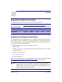
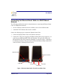
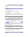
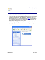
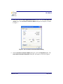
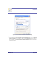
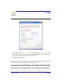
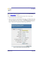
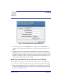
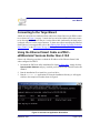
Ethernet Smart Cable User Manual UM020705-1012 Introduction Zilog’s Ethernet Smart Cable, part number ZENETSC0100ZACG, allows you to connect Z8 Encore!®, Z8 Encore! XP®, ZNEO™ and eZ80Acclaim!® development boards to a Zilog Developer Studio II (ZDS II) host system using an Ethernet connection. This user manual provides instructions for installing the Ethernet Smart Cable hardware. Instructions are also provided for Ethernet-equipped host PCs that are not network-connected. After the Ethernet Smart Cable is connected, proceed with debugging as described in the documentation specific to your development kit. Kit Contents To determine the contents of your kit, refer to the Ethernet Smart Cable Packing List (PAK0019), a paper insert included with your kit. Software and Hardware Requirements The requirements for using the Ethernet Smart Cable are: • A host PC with ZDS II v4.10.0 or later for Z8 Encore!, eZ80Acclaim!, or ZNEO. To determine ZDS II requirements for your host system, refer to the quick start guide for your specific development kit. The latest version of ZDS II is available as a free download from the Zilog Store. • An available 10/100 Mbps Ethernet connection. Note: If you are using ZDS II – eZ80Acclaim! versions earlier than 4.10.0, see the Using the Ethernet Smart Cable on ZDS II – eZ80Acclaim! Versions Earlier than 4.10.0 section on page 11. Copyright ©2012 Zilog®, Inc. All rights reserved. www.zilog.com Ethernet Smart Cable User Manual Supported Target Environments The supported target environments are described in the following table. System Clock Power Supply Minimum Maximum Minimum Maximum Current* Z8 Encore! 32 kHz 20 MHz 2.7 V 3.6 V 2 mA ZNEO 10 kHz 20 MHz 2.7 V 3.6 V 2 mA eZ80Acclaim! 5 MHz 50 MHz 3.0 V 3.6 V 2 mA Development Board Note: *Add this Ethernet Smart Cable current as a requirement for your target’s power supply. Installing the Ethernet Smart Cable The Ethernet Smart Cable is optimized for use on an Ethernet network in which a dynamic host configuration protocol (DHCP) server assigns IP addresses. The following sections provide instructions for connecting the Ethernet Smart Cable to a DHCP-based network, or directly to an Ethernet-equipped host PC. The Ethernet Smart Cable’s factory default settings include: • • DHCP enabled • • • Subnet mask: 255.255.255.0 IP address: 192.168.1.50 (this address will be different if a DHCP server is available to assign an address) Gateway: 192.168.1.254 No password required If you need to change the cable’s factory default settings, follow the steps described in the Changing the Default Settings of the Ethernet Smart Cable section on page 8. Note: When a DHCP server is unavailable, the Ethernet Smart Cable defaults to using IP address 192.168.1.50. If your network uses static IP addresses on a different subnet, connect the Ethernet Smart Cable to a stand-alone PC configured as described in the next section. UM020705-1012 Page 2 of 13 Ethernet Smart Cable User Manual Connecting the Ethernet Smart Cable to a DHCP-Based Network The following considerations must be determined prior to connecting the Ethernet Smart Cable to a DHCP-based network: • • An active Ethernet connection must be available, such as from an Ethernet hub A standard CAT-5 Ethernet cable must be available Observe the following steps to connect the Ethernet Smart Cable: 1. Connect the Ethernet Smart Cable to an Ethernet connection. 2. Connect the 5 V DC power supply to the Ethernet Smart Cable power connector. As a result, the green PWR and RUN LEDs will illuminate. The green link LED on the Ethernet Smart Cable RJ-45 connector illuminates, as shown in Figure 1, indicating a live Ethernet connection. The green activity LED on the Ethernet Smart Cable RJ-45 connector flickers, indicating network activity. DBG Connector Ethernet Connector PWR LED RUN LED 5 VDC Power In Link LED Activity LED Figure 1. Ethernet Smart Cable, Front View and Rear View UM020705-1012 Page 3 of 13 Ethernet Smart Cable User Manual 3. Launch ZDS II. 4. Navigate via the File menu in ZDS II to open one of the projects listed in the samples directory of your ZDS II installation. 5. Select Project Settings to display the Project Settings dialog. 6. Select the Debugger tab. 7. From the Debug Tool drop-down menu, select EthernetSmartCable. 8. Click the Setup button. Your Ethernet Smart Cable will be listed in the Smart Cables Available list. Select the checkbox for your Ethernet Smart Cable, then click the OK button. Note: If you have more than one Ethernet Smart Cable, you can uniquely identify them by comparing the MAC address listed in the Smart Cables Available list with the label on the bottom of the Ethernet Smart Cable. 9. Click the OK button in the Project Settings window. Your project is now configured to run with the newly installed Ethernet Smart Cable. 10. Connect the target board to the Ethernet Smart Cable as described in the Connecting to the Target Board section on page 11. Connecting the Ethernet Smart Cable Directly to a Host PC When using a host PC that is not network-connected, configure the PC as follows to connect it to the Ethernet Smart Cable. Note: The following instructions are designed for use on a MS Windows XP platform. If your Windows operating system is different, refer to MS Windows OS online help for details. Observe the following steps to connect the Ethernet Smart Cable to a host PC: 1. Power on your host PC before proceeding. UM020705-1012 Page 4 of 13 Ethernet Smart Cable User Manual 2. Use the Ethernet crossover cable supplied with the Ethernet Smart Cable to connect the Ethernet Smart Cable to the host PC’s Ethernet port. 3. Connect the 5 V DC power supply to the Ethernet Smart Cable power connector. As a result, the green PWR and RUN LEDs will illuminate. The green link LED on the Ethernet Smart Cable’s RJ-45 connector illuminates (see Figure 1 on page 3), indicating a live Ethernet connection. The green activity LED on the Ethernet Smart Cable RJ-45 connector flickers, indicating network activity. 4. On the host PC, open the Windows Control Panel and double-click the Network and Internet Connections icon. The Network Connections dialog box will appear, as shown in Figure 2. Figure 2. The Network Dialog UM020705-1012 Page 5 of 13 Ethernet Smart Cable User Manual 5. In the panel labeled LAN or High-Speed Internet, double-click the Local Area Connection icon. The Local Area Connection Status dialog box will appear, as shown in Figure 3. Figure 3. The Local Area Connection Status Dialog 6. In the Local Area Connection Status dialog box, click the Properties button. The Local Area Connection Properties dialog box will appear, as shown in Figure 4. UM020705-1012 Page 6 of 13 Ethernet Smart Cable User Manual Figure 4. The Local Area Connection Properties Dialog 7. In the panel labeled This connection uses the following items:, select the Internet Protocol (TCP/IP) item to highlight it, and click the Properties button (see Figure 4 for an example). The Internet Protocol (TCP/IP) Properties dialog box will appear, as shown in Figure 5. UM020705-1012 Page 7 of 13 Ethernet Smart Cable User Manual Figure 5. The Internet Protocol Properties Dialog 8. Enter an IP address of 192.168.1.21 and a subnet mask of 255.255.255.0. These values place the PC on the same network as the Ethernet Smart Cable, and do not conflict with the IP address of the Ethernet Smart Cable. 9. Click OK and restart the PC. The PC is now ready to communicate with Ethernet Smart Cable via the ZDS II software. The default IP address of the Ethernet Smart Cable unit is 192.168.1.50. Changing the Default Settings of the Ethernet Smart Cable The Ethernet Smart Cable is equipped with a web interface that allows you to change its default settings. To access the Ethernet Smart Cable web interface, you must know the UM020705-1012 Page 8 of 13 Ethernet Smart Cable User Manual cable’s IP address, which can be obtained from ZDS II in the ZDS II Project Settings window; see Steps 5 through 9 on page 4). Observe the following steps to change the Ethernet Smart Cable’s default settings: 1. Obtain the Ethernet Smart Cable IP address. 2. Open your web browser to the IP address located in Step 1. The Ethernet Smart Cable home page will appear, as shown in Figure 6. The Settings tab on this page provides access to the Ethernet Smart Cable’s network settings. The Password tab, shown in Figure 7, allows you to set a password for Ethernet Smart Cable access. Figure 6. Ethernet Smart Cable Home Web Page UM020705-1012 Page 9 of 13 Ethernet Smart Cable User Manual Figure 7. Ethernet Smart Cable Password Web Page 3. After the configuration in the Settings tab are changed, click the Submit button. A message acknowledging that changes have been made will appear beneath the web page. 4. To make the changes permanent, reboot the Ethernet Smart Cable by pressing the Reboot button. As a result, the Ethernet Smart Cable will reboot. If you have changed the cable’s IP address, redirect the web browser to point to the new IP address. If the IP address remains at its previous setting, the Ethernet Smart Cable home page will appear again, displaying the changes you made. Restoring the Ethernet Smart Cable Factory Settings Observe the following steps to restore the Ethernet Smart Cable to its factory settings. 1. Locate the reset switch access hole in the side of the Ethernet Smart Cable housing. 2. Using a straightened paper clip, press and hold the reset switch for six seconds. The Run LED will extinguish while the switch is pressed, and will illuminate again after the factory settings are restored. UM020705-1012 Page 10 of 13 Ethernet Smart Cable User Manual Connecting to the Target Board Attach one end of the six-conductor ribbon cable to the Smart Cable six-pin DBG connector, as shown in Figure 1 on page 3. Attach the free end of the ribbon cable to the connector on the target board. Ensure that pin 1 on the ribbon cable (indicated by the dark stripe) is aligned with pin 1 on the target connector. To learn more about connecting the Ethernet Smart Cable to your target board, refer to the eZ80Acclaim! Design for Debug Technical Note (TN0035) or the Z8 Encore! Design for Debug Technical Note (TN0036). Using the Ethernet Smart Cable on ZDS II – eZ80Acclaim! Versions Earlier than 4.10.0 Observe the following procedure to obtain the IP address of the Ethernet Smart Cable when configured for DHCP. 1. Download the ESCScan utility installation file from the Zilog Store; simply click the Downloadable Software category, in which you’ll find ESCScan listed as Product ID SD0012. 2. Run the installation file to install it to your local drive. 3. Run the escscan.exe application file from the installation directory; it will appear similar to the example screenshot shown in Figure 8. Figure 8. escscan.exe Application Screenshot UM020705-1012 Page 11 of 13 Ethernet Smart Cable User Manual 4. Note the IP Address. If you have several Ethernet Smart Cables connected to the network, an IP address will be shown for each particular Ethernet Smart Cable’s MAC address. 5. Press any key to exit the utility. 6. You must use the IP address determined in Step 4 when configuring ZDS II; simply navigate via ZDS II Project → Settings → Debugger → Configure ZPAK II → IP Address. For more information about this utility, refer to its readme.txt document. Troubleshooting Tips If a hardware failure is suspected, contact support.zilog.com for assistance. However, before submitting a problem report to Zilog Customer Support, follow the instructions in this section. ZDS II Cannot See the Ethernet Smart Cable If ZDS II cannot detect the Ethernet Smart Cable, try the following workarounds: • Remove power from the Ethernet Smart Cable, wait five seconds, then reapply power. Refresh the list of available smart cables. The Ethernet Smart Cable should now appear. • Verify that the Ethernet cable you are using is the correct type. (If you are connecting the Ethernet Smart Cable directly to a PC, you must use a crossover cable. Do not use a crossover cable to connect the Ethernet Smart Cable to a hub or standard Ethernet connection.) • Verify that UDP port 3000 is open in your local firewall. The ZDS II software uses UDP port 3000 to search for Ethernet Smart Cable IP addresses and requires access to that port through your local firewall. After the port is open, ZDS II should then be able to identify the IP address assigned to the Ethernet Smart Cable by your DHCP server. UM020705-1012 Page 12 of 13 Ethernet Smart Cable User Manual Warning: DO NOT USE THIS PRODUCT IN LIFE SUPPORT SYSTEMS. LIFE SUPPORT POLICY ZILOG'S PRODUCTS ARE NOT AUTHORIZED FOR USE AS CRITICAL COMPONENTS IN LIFE SUPPORT DEVICES OR SYSTEMS WITHOUT THE EXPRESS PRIOR WRITTEN APPROVAL OF THE PRESIDENT AND GENERAL COUNSEL OF ZILOG CORPORATION. As used herein Life support devices or systems are devices which (a) are intended for surgical implant into the body, or (b) support or sustain life and whose failure to perform when properly used in accordance with instructions for use provided in the labeling can be reasonably expected to result in a significant injury to the user. A critical component is any component in a life support device or system whose failure to perform can be reasonably expected to cause the failure of the life support device or system or to affect its safety or effectiveness. Document Disclaimer ©2012 by Zilog, Inc. All rights reserved. Information in this publication concerning the devices, applications, or technology described is intended to suggest possible uses and may be superseded. ZILOG, INC. DOES NOT ASSUME LIABILITY FOR OR PROVIDE A REPRESENTATION OF ACCURACY OF THE INFORMATION, DEVICES, OR TECHNOLOGY DESCRIBED IN THIS DOCUMENT. ZILOG ALSO DOES NOT ASSUME LIABILITY FOR INTELLECTUAL PROPERTY INFRINGEMENT RELATED IN ANY MANNER TO USE OF INFORMATION, DEVICES, OR TECHNOLOGY DESCRIBED HEREIN OR OTHERWISE. The information contained within this document has been verified according to the general principles of electrical and mechanical engineering. Z8 Encore!, Z8 Encore! XP, ZNEO and eZ80Acclaim! are trademarks or registered trademarks of Zilog, Inc. All other product or service names are the property of their respective owners. UM020705-1012 Page 13 of 13 Mouser Electronics Authorized Distributor Click to View Pricing, Inventory, Delivery & Lifecycle Information: ZiLOG: ZENETSC0100ZACG