1
LogiCORE IP Block Memory Generator v6.1
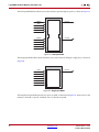
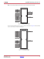
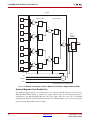
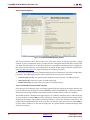
The MUX size displayed in the GUI can be used to determine the number of pipeline stages to use
within the MUX. Select the appropriate number of pipeline stages for your design based on the
device architecture.
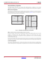
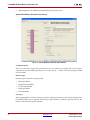
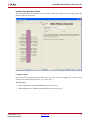
Memory Initialization
Select whether to initialize the memory contents using a COE file, and whether to initialize the
remaining memory contents with a default value. When using asymmetric port widths or data widths,
the COE file and the default value are with respect to the port A Write width.
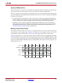
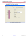
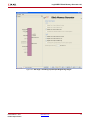
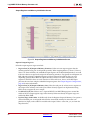
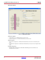
Reset Options Screen
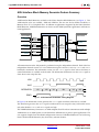
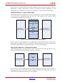
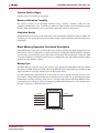
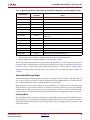
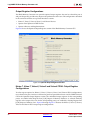
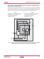
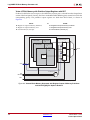
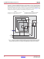
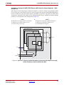
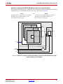
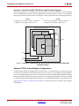
X-Ref Target - Figure 57
Figure 57: Reset Options Screen
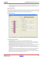
Port [A|B] Output Reset Options
•
Use RST[A|B] Pin: Choose whether a set/reset pin (RST[A|B]) is needed.
•
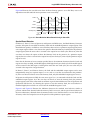
Reset Priority: The Reset Priority option for each port is available only when the Use RST Pin
option of the corresponding port is chosen. The user can set the reset priority to either CE or SR.
For more information on the reset priority feature, see Reset Priority, page 38.
•
Reset Behavior: The Reset Behavior (Reset Memory Latch) options for each port are available only
when the Use RST Pin option and the Register Output of Memory Primitives option of the
corresponding port are chosen, and the Register Memory Core option of the corresponding port is
not chosen.
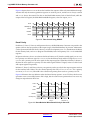
The Reset Memory Latch option modifies the behavior of the reset and changes the duration for
which the reset value is asserted. The minimum duration of reset assertion is displayed as
information in the GUI based upon the choice for this option. For more information on the Reset
Memory Latch option, see Special Reset Behavior, page 39.
DS512 March 1, 2011
Product Specification
www.xilinx.com
69