1
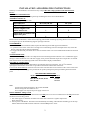
2. To LOWER water temperature, simply turn knob one notch counter-clockwise to next lower
number on dial.
HINT: To measure water temperature accurately, remove the spray-head for a solid water stream.
SOLID STATE WATER LEVEL CONTROL AND PROBE
WATER LEVEL CONTROL OPERATION
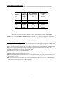
Components involved:
1. Solid state water level control board
Part
#L398A
2. Water inlet valve
Pan
# L397A
3. Water level probe
Part
#K213A
4. Hi-level float switch
Part
#L380A
Under normal conditions and operation, the water level in the lank should not drop more than 1/2" from the
probe. If it does, the tank is not being re-filled fast enough. Check the water line and water filter, they may need
cleaning or replacing.
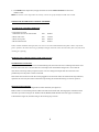
PROBLEM: NO WATER IS GOING TO THE TANK AT ALL!
WATER INLET VALVE TEST
Turn power off. If the water level rises inside the heating tank, the water inlet valve is leaking. Disconnect wires
from the water inlet valve coil and connect a 2 wire lamp cord to the terminals. Plug it into a 115V outlet. If
water flows in and stops when you pull it out, the valve is working fine. Repeat this test a few times. The
problem may be in the probe or water level board.
If the water does not flow in when the cord is plugged into an electrical outlet, the solenoid coil may be burned,
opened or the valve may have been an obstruction preventing the water from flowing in. Clean or replace it.
Hl-LEVEL FLOAT SWITCH
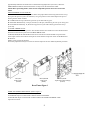
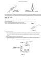
For BC2 and BC302 units with hinged Hi-level Float Switches, (See figure 4a)
Remove tank cover and check position of Hi-Level float switch inside tank. The hinged part of the float switch
must face up as shown in Figure 4a. The BC1, BC120, BC240, and BC302 units have ball type level detectors
as illustrated in Figure 4b; the ball resting on the retaining clip is shown.
6