1
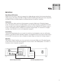
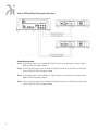
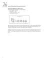
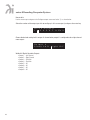
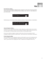
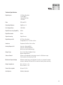
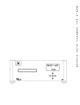
931/ 922 Decoding Computer System
Information&Operation Manual
931/ 922 Decoding Computer System
series 9 Decoding Computer System Information&Operation Manual
Table of Contents
Preliminaries
Brief History. . . . . . . . . . . . . . . . . . . . . . . . . . . . . . . . . . . . . . . . . . . . . . . . . . . . . . . . . . . . . . . . . . . . . . . . .3
Overview . . . . . . . . . . . . . . . . . . . . . . . . . . . . . . . . . . . . . . . . . . . . . . . . . . . . . . . . . . . . . . . . . . . . . . . . . . . .4
How to Use this Manual . . . . . . . . . . . . . . . . . . . . . . . . . . . . . . . . . . . . . . . . . . . . . . . . . . . . . . . . . . . . . . .4
Inventory . . . . . . . . . . . . . . . . . . . . . . . . . . . . . . . . . . . . . . . . . . . . . . . . . . . . . . . . . . . . . . . . . . . . . . . . . . .4
Quick Start
Set-up . . . . . . . . . . . . . . . . . . . . . . . . . . . . . . . . . . . . . . . . . . . . . . . . . . . . . . . . . . . . . . . . . . . . . . . . . . . . .5
Installation and Set-up
Unpacking . . . . . . . . . . . . . . . . . . . . . . . . . . . . . . . . . . . . . . . . . . . . . . . . . . . . . . . . . . . . . . . . . . . . . . . . . .7
Placement . . . . . . . . . . . . . . . . . . . . . . . . . . . . . . . . . . . . . . . . . . . . . . . . . . . . . . . . . . . . . . . . . . . . . . . . . .7
Installing the Tip-Toes . . . . . . . . . . . . . . . . . . . . . . . . . . . . . . . . . . . . . . . . . . . . . . . . . . . . . . . . . . . . . . . .7
Connecting the 931 to a Digital Source. . . . . . . . . . . . . . . . . . . . . . . . . . . . . . . . . . . . . . . . . . . . . . . . . . .8
Connecting the 931 and 922 . . . . . . . . . . . . . . . . . . . . . . . . . . . . . . . . . . . . . . . . . . . . . . . . . . . . . . . . . .10
Connecting the 922 to an Amplifier . . . . . . . . . . . . . . . . . . . . . . . . . . . . . . . . . . . . . . . . . . . . . . . . . . . .12
Illuminated Status Indicator . . . . . . . . . . . . . . . . . . . . . . . . . . . . . . . . . . . . . . . . . . . . . . . . . . . . . . . . . .13
Maximum Output Level Setting . . . . . . . . . . . . . . . . . . . . . . . . . . . . . . . . . . . . . . . . . . . . . . . . . . . . . . .13
Choosing a Digital Cable . . . . . . . . . . . . . . . . . . . . . . . . . . . . . . . . . . . . . . . . . . . . . . . . . . . . . . . . . . . . .14
Frequently Asked Questions . . . . . . . . . . . . . . . . . . . . . . . . . . . . . . . . . . . . . . . . . . . . . . . . . . . . . . . . . .15
Operation and Configuration
Front Panel Controls . . . . . . . . . . . . . . . . . . . . . . . . . . . . . . . . . . . . . . . . . . . . . . . . . . . . . . . . . . . . . . . .16
Remote Control Commands . . . . . . . . . . . . . . . . . . . . . . . . . . . . . . . . . . . . . . . . . . . . . . . . . . . . . . . . . .17
Operational Screens . . . . . . . . . . . . . . . . . . . . . . . . . . . . . . . . . . . . . . . . . . . . . . . . . . . . . . . . . . . . . . . .18
Additional Features . . . . . . . . . . . . . . . . . . . . . . . . . . . . . . . . . . . . . . . . . . . . . . . . . . . . . . . . . . . . . . . . .21
Configuration . . . . . . . . . . . . . . . . . . . . . . . . . . . . . . . . . . . . . . . . . . . . . . . . . . . . . . . . . . . . . . . . . . . . . . .22
Configuring Inputs . . . . . . . . . . . . . . . . . . . . . . . . . . . . . . . . . . . . . . . . . . . . . . . . . . . . . . . . . . . . . . . . . .24
Configuring Outputs . . . . . . . . . . . . . . . . . . . . . . . . . . . . . . . . . . . . . . . . . . . . . . . . . . . . . . . . . . . . . . . . .25
Restoring Settings . . . . . . . . . . . . . . . . . . . . . . . . . . . . . . . . . . . . . . . . . . . . . . . . . . . . . . . . . . . . . . . . . .27
Appendices
Troubleshooting . . . . . . . . . . . . . . . . . . . . . . . . . . . . . . . . . . . . . . . . . . . . . . . . . . . . . . . . . . . . . . . . . . . .28
Software License Agreement . . . . . . . . . . . . . . . . . . . . . . . . . . . . . . . . . . . . . . . . . . . . . . . . . . . . . . . .28
Technical Specifications . . . . . . . . . . . . . . . . . . . . . . . . . . . . . . . . . . . . . . . . . . . . . . . . . . . . . . . . . . . . .29
Safety Precautions . . . . . . . . . . . . . . . . . . . . . . . . . . . . . . . . . . . . . . . . . . . . . . . . . . . . . . . . . . . . . . . . .30
Warranty . . . . . . . . . . . . . . . . . . . . . . . . . . . . . . . . . . . . . . . . . . . . . . . . . . . . . . . . . . . . . . . . . . . . . . . . . .31
2
Thank You
All of us at Wadia would like to offer thanks and congratulations to you for purchasing the Wadia series 9
Decoding Computer System. We sincerely believe that your Wadia series 9 Decoding Computer System will
bring you many years of musical pleasure and satisfaction.
While every new owner is anxious to begin listening, we encourage you to take a few minutes to read and
familiarize yourself with the full capabilities of the Wadia series 9 Decoding Computer System.
Brief History
Wadia was originally founded in 1988, making it one of the first high-end audio companies dedicated to digital
audio. Wadia was formed by a group of engineers who were committed to using advanced digital technology to
improve the performance of digital audio equipment.
Wadia’s first product, the Wadia 2000 Decoding Computer, was a breakthrough. For many listeners it proved the
viability of the Compact Disc as a musically involving format. Since then Wadia has continued to develop new
methods and technology. Each product resulted in a new standard of performance for digital audio decoding.
Here is an abbreviated list of the technological innovations Wadia engineers have pioneered:
• First company to introduce an outboard Digital-to-Analog converter
• First company to develop an audio optimized upsampling digital filter
• First company to apply glass fiber-optics to home audio
• First company to recognize clock-jitter as a source of audible distortion
• First company to test and apply mechanical de-tuning to the development of audio
component chassis design
• First company to offer a CD perfect digital volume control
• First company to develop a Direct to Digital Amplifier - PowerDAC
• Patented DigiMaster™ upsampling algorithm, optimized for reproducing music
• RocLock proprietary jitter reduction technology
• ClockLink™ proprietary jitter reduction technology
• SwiftCurrent™ zero-feedback current to voltage converter
• DirectConnect system to connect digital audio products directly to an amplifier
Although Wadia’s digital expertise and track record exceed those of any other audio company, technology alone
does not guarantee musical performance. Wadia designs are born of a delicate balance of technology shaped by
a passion for music.
Wadia is proud to introduce the Wadia series 9 Decoding Computer System, a breakthrough in sonic performance
and a strong statement of our years of dedication to music.
3
series 9 Decoding Computer System
Overview
This manual covers the installation and operation of the complete Wadia series 9 Decoding Computer System.
There are three steps to a complete installation:
• Installation and configuration of the Wadia 931 Digital Controller
• Installation and configuration of the Wadia 922 Mono Decoding Computers
• Operation of the Wadia series 9 Decoding Computer System
How to Use this Manual
Included in this manual is all the information you need to completely install and operate the Wadia series 9
Decoding Computer System. For a complete set-up, we recommend that you follow the installation and operation
instructions from start to finish. If you already have experience installing, configuring, and operating Wadia
components, you can use the Quick Start section, and refer to the complete instructions where needed.
Inventory
Before proceeding, please check to make sure that you received all of the components that comprise
the Wadia series 9 Decoding Computer System. You should have received the following boxes:
Wadia 931 Digital Controller
• Accessory kit
• Remote control
• 1 Glass fiber cable, 10 feet long
• AC power cord (12 gauge)
• Three tip-toes with threaded studs
• Three steel coasters
• 1 BNC to RCA adapter
Wadia 922 Mono Decoding Computers (one per channel)
• Accessory kits
• 2 Glass fiber cables, 35 feet long
• AC power cord (12 gauge)
• Three tip-toes with threaded studs
• Three steel coasters
For a standard 2-channel set-up you should have 3 boxes and 3 accessory kits. If you did not receive all cartons,
contact your dealer before continuing.
4
Quick Start
Unpacking and Placement
Unpack each of the cartons. Check each component for shipping damage and verify that the operating voltage
matches your local AC voltage. The Wadia 931 Digital Controller should be positioned near the source components,
the Wadia 922 Mono Decoding Computers should be placed near the amplifier or amplifiers.
Connections
Use the illustrations below and on the following page to connect the Wadia series 9 Decoding Computer
System. All rear-panel connectors are labeled. Input 1 on the 931 Digital Controller is configured for ClockLink.
If you are using a source component equipped with ClockLink, such as the Wadia 270 CD transport, connect it
to Input 1. Non-ClockLink sources should not be connected to ClockLink inputs. For instructions to configure
any input to turn ClockLink on or off, see Configurations on page 22.
Level Setting
The Maximum Output Level can be set to match the sensitivity of your loudspeaker, room size, and listening
preference. The Wadia 922 Mono Decoding Computers come shipped from the factory with the output level set
at 2 volts RMS. For instruction on how to configure the output voltage see Output Level Settings on page 13.
Operation
The Wadia 931 Digital Controller acts as the user-interface for the entire Wadia series 9 Decoding Computer
System and uses remote commands and operations that are similar to other Wadia products. For a full list of
instructions, refer to Operations on page 16.
ClockLink Cable
Data Cable
Wadia 931 Digital Controller
ClockLink-Equiped Digital Source
5
series 9 Decoding Computer System
Standard Configuration:
Step 1: Connect data output 1 from the Wadia 931 Digital Controller to the data input of the left channel
Wadia 922 Mono Decoding Computer.
Step 2: Connect ClockLink output 2 from the Wadia 931 Digital Controller to the ClockLink input of the left
channel Wadia 922 Mono Decoding Computer.
Step 3: Connect data output 3 from the Wadia 931 Digital Controller to the data input of the right channel
Wadia 922 Mono Decoding Computer.
Step 4: Connect ClockLink output 4 from the Wadia 931 Digital Controller to the ClockLink input of the right
channel Wadia 922 Mono Decoding Computer.
6
Installation and Set-up
Unpacking
Carefully unpack your Wadia 931 Digital Controller and the two Wadia 922 Mono Decoding Computers. Inspect
the outside of the chassis for shipping damage. If you find any, report it to your dealer immediately.
Do not plug in the Wadia 931 Digital Controller if you see any signs of shipping damage.
Please save all packing materials so the unit can be easily and safely shipped if the need arises.
Placement
Wadia 931 Digital Controller
Much like an analog preamplifier, the Wadia 931 Digital Controller should be centrally located near your
source components. Because the Wadia 931 Digital Controller is connected to the Wadia 922 Mono Decoding
Computers via glass fiber cabling, there is no advantage to placing it nearby these units.
Wadia 922 Mono Decoding Computers
The Wadia 922 Mono Decoding Computers should be placed as near to the amplifier or amplifiers as possible.
This will allow you to use shorter interconnecting cables thereby maximizing system performance.
AC Power
Please check to see what AC line voltage your unit is set for. Connecting to any voltage other than that specified
on the back panel will result in damage that is not covered by the warranty.
We recommend that you do not turn on the AC power until you have completed all connections between the
components of your system.
Installing the Tip-Toes
Screw one of the tip-toes under each of the three recesses in the bottom of the Wadia 931 Digital Controller and
both of the Wadia 922 Mono Decoding Computers. If the surface on which you intend to place the Wadia 931
Digital Controller is susceptible to damage, make sure to place one of the steel coasters under each tip-toe.
7
series 9 Decoding Computer System
Connecting the Wadia 931 to a Digital Source
The Wadia 931 Digital Controller has six digital inputs:
• 2 glass fiber (ST) - Input 1,2
• 2 SPDIF (BNC) – Input 3,4
• 1 plastic fiber (TOSLINK) – Input 5
• 1 AES/EBU (XLR) – Input 6
Note: Input One is factory-configured for a ClockLink enabled source, such as a Wadia 270 CD Transport.
Using a non-ClockLink source connected to a ClockLink input degrades the sonic performance. To
change the configuration of any input, see Configuring Inputs on page 26.
Any digital source with one of these types of outputs can be connected to the Wadia 931 Digital Controller. The
931 Digital Controller will automatically detect and lock on to any of the established digital audio transmission
formats — up to a 96 kHz sampling rate. For more information on cable types, see Choosing a Digital Cable on
page 14.
8
Wadia Digital Sources with ClockLink
The Wadia 931 Digital Controller serves as the reference clock for your entire Wadia digital system. The Wadia
931 Digital Controller uses a ultra-stable Temperature-Controlled Crystal Oscillator (TCXO) as a master clock and
is further enhanced by a superior power supply.
The Wadia 931 Digital Controller has a ClockLink output for source components, such as a Wadia 270
CD Transport. To link the Wadia 270 CD transport, connect an ST glass fiber cable from the Wadia 931
Digital Controller‘s ClockLink output, located near the digital inputs, to the source component’s
ClockLink input.
ClockLink Cable
Data Cable
Wadia 931 Digital Controller
ClockLink-Equiped Digital Source
9
series 9 Decoding Computer System
Connecting the 931 and 922
Wadia 931 Digital Controller Outputs
There are nine outputs on the Wadia 931 Digital Controller. One is dedicated for ClockLink and can be used to
connect to a Clocklink enabled source. All of the other outputs can be configured as either ClockLink or Data
outputs. This allows the Wadia 931 Digital Controller to be used in a variety of system configurations. To change
the configuration of the outputs, see Configurations on page 24.
Wadia 931 Digital Controller digital outputs.
Wadia 922 Decoding Computer Inputs
The Wadia 922 Mono Decoding Computer has 2 inputs, both ST glass fiber, which comprise Wadia’s proprietary
Dual-fiber Digital Interface. As currently configured, this interface uses one for data (up to 96 kHz, 24-bit),
and one for clock.
Connect the two fiber cables from your Wadia 931 Digital Controller to the ClockLink and Data input.
10
Connecting to 922 Mono Decoding Computers
Step 1: Connect data output 1 from the Wadia 931 Digital Controller to the data input of the left channel
Wadia 922 Mono Decoding Computer.
Step 2: Connect ClockLink output 2 from the Wadia 931 Digital Controller to the ClockLink input of the left
channel Wadia 922 Mono Decoding Computer.
Step 3: Connect data output 3 from the Wadia 931 Digital Controller to the data input of the right channel
Wadia 922 Mono Decoding Computer.
Step 4: Connect ClockLink output 4 from the Wadia 931 Digital Controller to the ClockLink input of the right
channel Wadia 922 Mono Decoding Computer.
Note: If you do not connect a ClockLink cable, the Wadia 922 Mono Decoding Computer will not run in
ClockLink mode and performance will not reach full potential.
If you connect a data source other than a Wadia Digital Controller such as the 931, the Wadia 922
Mono Decoding Computer will not operate.
11
series 9 Decoding Computer System
Connecting to Wadia 922 Mono Decoding Computers
The Wadia 922 Mono Decoding Computer has 2 outputs:
• Line-level unbalanced analog on RCA
• Line-level balanced analog on XLR
Connecting Directly to an Amplifier
We strongly recommend that you connect your Wadia series 9 Decoding Computer System directly to your
power amplifier. Even if you purchased your Wadia series 9 Decoding Computer system with the intention of
connecting it through a preamplifier, we suggest that you experiment with direct connection to your amplifier.
Many listeners are surprised by the improvement in performance over even the most expensive preamplifiers. If
you would like more information about getting best performance from a system without a preamplifier, contact
your Wadia dealer.
To connect your Wadia series 9 Decoding Computer System to a power amplifier, ensure that your power amplifier
is turned off, then connect your analog interconnects from the Wadia 922 Mono Decoding Computers balanced
or unbalanced analog outputs to the amplifier’s inputs.
Connecting to a Preamplifier
While the Wadia series 9 Decoding Computer System was designed to be used without a preamplifier, it will
provide excellent operation in a conventional system with a preamplifier. Simply connect the analog outputs
from the Wadia 922 Mono Decoding Computers to a pair of line-level inputs on the preamplifier.
When using a preamplifier, disable the Wadia series 9 Decoding Computer System volume control by setting the
Wadia 931 Digital Controller to its maximum volume.
Powering up
To turn the Wadia 922 Mono Decoding Computer on, plug the unit in. Under normal conditions, the Wadia
series 9 Decoding Computer System should be left with the power on. To reduce power consumption, you can
put your system in the Standby Mode, by setting the Wadia 931 Digital Controller volume to zero, and pressing
mute on the remote control. For more information, see Standby on page 21.
12
Illuminated Status Indicator
There is a multi-colored LED at the base of the front of the Wadia 922 Mono Decoding Computer. This
LED indicates the status of the Wadia 922 Mono Decoding Computers, as follows:
• Blue
Unit is in operate mode
• Red
Unit is powered up, but in Standby Mode
• Flashing Red
Output protection is engaged (contact your dealer)
Status Indicator
Wadia 922 Mono Decoding Computers Maximum Output Level Setting
For optimum performance, the Wadia 922 Mono Decoding Computer output level should be set so that critical
listening occurs with the volume control near the top of its range, above 70. The Maximum Output Level is adjusted
by means of a set of switches located on the back panel of the Wadia 931 Decoding Computer, with 4.4 Volts RMS
being the loudest setting. If more than one switch is active, the highest voltage setting will override.
Output Voltage Table:
4.4 Volts RMS
2.2 Volts RMS*
1.1 Volt RMS
0.5 Volts RMS
*Factory default setting
Switch 1 On
Switch 2 On
Switch 3 On
Switch 4 On
Output Level
Note: Before adjusting the output level, make sure you put the Wadia 922 Mono Decoding Computers
into the Standby Mode. You can put the Wadia series 9 Decoding Computer System in the Standby
Mode by setting the Wadia 931 Digital Controller volume to zero, and pressing mute on the remote
control. For more information, see Standby on page 21.
13
series 9 Decoding Computer System
Choosing a Digital Cable
While the Wadia series 9 Decoding Computer System supports all currently accepted transmission formats for
digital audio, we recommend using the glass optical cable that is included in your accessory kit. Wadia Digital
was the first company to use glass fiber-optic data transmission in digital audio. We have continually improved
this format and believe that it offers the best, most consistent performance of all the available options.
Based on our experience, here is a list of digital interface methods in descending order of performance:
1. Glass optical (as implemented by Wadia)
2. AES/EBU using XLR connector
3. Coaxial cable using BNC connector
4. Coaxial cable using RCA connector
5. TOSLINK plastic-optical cable
The quality of any of these transmission methods depends on the quality of the cable and the sophistication of
the transmitter and receiver. For example, a high-quality coaxial cable can outperform a low-quality AES/EBU
cable. A high-quality AES/EBU cable will outperform a poorly-implemented glass-optical system. We recommend
that if you are using a coaxial cable, have the cable terminated with a BNC connector. This will provide higher
performance than an RCA connector. Your Wadia series 9 Decoding Computer System comes with an RCA/BNC
adapter that can be used for experimentation between different types of RCA terminated coaxial cable. Again,
we highly recommend that you take advantage of your dealer’s experience and, most importantly, trust your ears.
All XLR-type inputs and outputs on the Wadia series 9 Decoding Computer System, both digital and
analog, use the standard audio pin configuration:
• Pin 1 - Ground
• Pin 2 - Positive signal
• Pin 3 - Negative signal
14
Frequently Asked Questions
Should I use a Power Line Conditioner?
The Wadia 931 Digital Controller and Wadia 921 Mono Decoding Computers are designed to be used without
AC power line conditioners. Similarly, Wadia products are designed to achieve outstanding performance with
the AC power cords included with the units.
If you wish to experiment, we recommend that you proceed with caution. Only purchase an after-market AC power
accessory if you are absolutely convinced that it improves sound quality. If you have any question, we strongly
recommend that you consult your dealer, or contact Wadia directly. Most importantly, trust your own ears.
Should I use a Balanced or Unbalanced connection?
If your amplifier has a true balanced input, we recommend you use the balanced analog output from your
Wadia series 9 Decoding Computer System.
All things being equal, properly implemented balanced (also called differential) circuitry sounds better than
unbalanced circuitry. The Wadia series 9 Decoding Computer System is a true balanced design. It generates the
inverted signal in the digital domain and all subsequent processing is done in balanced mode.
Your Wadia series 9 Decoding Computer System is designed to maintain many of the advantages of true balanced
design when using the unbalanced outputs. In addition, the Wadia 922 Mono Decoding Computer output stage
is capable of driving both types of outputs simultaneously.
Why should I bypass the Preamplifier?
A preamplifier is unnecessary when using your Wadia series 9 Decoding Computer System. The system provides
all of the necessary control function of a preamp while the signal is still in the digital domain. This avoids the
sonic degradation caused by analog circuitry, switches, and wire. The Wadia series 9 Decoding Computer System
output stage can drive any power amplifier and any interconnects, even at very long lengths.
Can I connect an Analog Source to my Wadia 931 Digital Controller?
Analog sources are connected to the Wadia 931 Digital Controller by using an analog-to-digital converter, such
as the Wadia 17, Wadia 130, or Wadia 150, to convert the signal to digital, and by connecting to any of the
Wadia 931 Digital Controller digital inputs.
Does the Wadia Volume Control compromise resolution?
Wadia’s patented digital filtering algorithm produces a 24 bit output rather than the 16 bits stored on a CD. This
high-resolution signal is then used in the computations which in turn reduce the volume level and is fed directly
to the DAC chips. This allows the Wadia to maintain high resolution at the lowest volume settings.
Can I bypass the Wadia Volume Control?
Because the Digital Volume Control does not include any analog circuitry, there is technically none to be bypassed.
If you would like to bypass the Wadia Volume Control, set it to its maximum level of 100 on the display.
15
series 9 Decoding Computer System
Operation and Configuration
Once the Wadia 931 Digital Controller and Wadia 922 Mono Decoding Computers are configured and installed in
your system, all operation is done by using the remote control and display screen on the Wadia 931 Digital Controller.
Front Panel Controls
There are five buttons on the front panel of the Wadia 931 Digital Controller.
During configuration mode, these buttons change functions (see Configuration).
16
UP/Down
These buttons perform the same function as the volume up and volume down keys on the
remote control. The volume is increased or decreased by 1 (0.5 dB). The volume control range
is from 1 (-50 dB) to 100 (0 dB). Setting the volume to zero completely mutes the output.
Left /Right
Scrolls to the next or previous enabled input in numerical order.
Enter
Scrolls to the next menu screen.
Wadia 931 Remote Control Commands
Below is a diagram of the functions for the Wadia 931 Digital Controller remote control. The remote control
requires a CR3032 battery. The battery should already be inside the remote. You will need to remove the plastic
battery protector from the battery chamber for the remote to work.
L
R
display
Display On-Off
phase
enter
input
Input
program
mode
1
2
3
4
5
6
7
8
9
Search Back
M
M
0
M
M
Search Forward
Stop / Volume Up
I
M
Play
M
M
mute
M
M
S
Balance Left-Right
SS
Key Pad
Drawer Open-Close
S
Track Back / Mute
S
Program / Mode
M
Phase Invert / Enter
Repeat
S
Track Forward
Volume Down / Pause
Note: All gray functions listed above
are compatible with Wadia transports.
See transport manual for specific
operation details.
Table of Wadia 931 Digital Controller Remote Functions
Button
Function
Mute
Mutes output.
Balance Left / Right
Increases balance to one channel by 0.2 db, and decreases the other by -0.2 db.
Input
Selects the next enabled input in numerical order.
Volume Up / Down
Increases or decreases volume by an increment of 1 on the display.
Phase Invert
Toggles between normal and inverted phase.
Display On-Off
Changes between Display on and off modes. In display off mode, the display is off, but
turns on for 5 seconds whenever any key is pressed. In display on mode, the display
stays on at all times.
Enter
Same as enter button on front panel.
17
series 9 Decoding Computer System
Operational Screens
There are 2 ways to navigate between the Operational Screens. The user can either scroll through them, or
access them directly.
The user can scroll in a loop through the Operational screens (plus the Enter Configuration Mode screen) by
pressing enter, either on the front panel or the remote control. After 10 seconds of no user activity, the display
will revert to the main screen.
Turn-on
W a d i a 9 3 1
D i g i t a l C o n t r o l l e r
10 sec
Main
L e v e l : 9 5
I N 2 : G l a s s
O p t i c a l
Enter
Status
9 6 k h z
Enter
E m p h a s i s : o f f
P h a s e : N o r m a l
Time Out
Enter
Balance
R i g h t
+ 0 . 2
B a l a n c e
L e f t
- 0 . 2
Enter
Configuration
Mode
18
E n t e r
C o n f i g
y / n
M o d e ?
Direct Access to Operational Screens
Anytime the user presses a command, the display jumps to that screen.
Balance Screen
Indicates the current right/left channel balance. The balance is adjusted by pressing the right and left balance
keys on the remote control. Each time a key is pressed, the volume on that channel is increased by 0.2 on the
display (0.1 dB) on that channel, and decreased by 0.2 on the display for the other channel.
If the user presses the left balance button once, the display looks like this:
R i g h t
+ 0 . 2
B a l a n c e
L e f t
- 0 . 2
If the left balance key is pressed five times, the display looks like this:
R i g h t
+ 1 . 0
B a l a n c e
L e f t
- 1 . 0
The balance control setting does not affect the volume control setting or the volume value displayed.
Pressing either balance key on the remote causes the display to jump to the balance screen, and adjusts the
balance in response to user input. After 5 seconds of no activity on the balance keys, the display reverts to the
main screen.
Status Screen
Shows the current settings for sample rate and emphasis (both auto-detected) and phase, normal or inverted
(user selected). After any parameter on this screen (sampling rate, emphasis, or phase) is changed, this screen
is displayed for a short time (approximately 2 seconds).
9 6 k h z
E m p h a s i s : o f f
P h a s e : N o r m a l
19
series 9 Decoding Computer System
Volume and Input
The volume can be controlled between 0 and 100. Each increment of 1 on the display is 0.5 dB, so the attenuation
range is from -50 dB at a volume setting of zero, to 0 dB at volume setting of 100. The display jumps to the
main screen whenever the volume or input is changed.
Mute
Mute is engaged by pressing the mute key on the remote control. The volume is set to zero by sending a stream
of zero data to the output, or by interrupting the output. When entering or leaving mute mode, the volume
ramps up or down such that it takes roughly 2 seconds to get from a volume of 100 to volume 0. Pressing mute
or volume up (but not volume down) disengages mute. Pressing Mute displays the main screen as shown:
L e v e l : 9 5
( m u t e )
I N 2 : G l a s s O p t i c a l
No Data
If there is no digital signal present on the selected input, the display indicates this by flashing the name of the
input alternately with the words “NO DATA”:
L e v e l : 9 5
I N 2 : N o D a t a
20
Additional Features
Standby
The Wadia series 9 Decoding Computer System can be put into Standby Mode. To enter standby mode, use
the volume down button to set the volume to zero. Then press the mute key. In Standby Mode, the power to
the output stage is turned off, and the output is muted. However, temperature-sensitive components remain
powered-up so that the system is ready for top performance as soon as operation begins.
The display will indicate standby as follows:
L e v e l : 0
( s t a n d b y )
I N 2 : G l a s s O p t i c a l
In addition, the indicator light on the Wadia 922 Mono Decoding Computer turns red when in standby. To leave
Standby mode, press volume up.
Sampling Rate Detect
The Wadia 931 Digital Controller automatically detects the sampling rate. Each time there is a change in sampling
rate, the unit displays the Status screen, showing the new sample rate, for approximately 2 seconds.
Emphasis Detect
Discs recorded with digital emphasis are automatically detected and this is displayed by switching to the Status
Screen for approximately 2 seconds. The Wadia 931 Digital Controller passes the emphasis bit through to the
Wadia 922 Mono Decoding Computers and the disc is decoded accordingly.
Next or Previous Input
When an input select button is pressed the following sequence occurs:
1. The display shows the new input number and label
2. The volume ramps down to mute (but the displayed volume setting does not change)
3. The unit locks onto the new signal and begins decoding
4. If the sampling rate or emphasis is changed, the Status screen indicates the new values
5. The volume ramps back up
6. If the input select button is pressed again at any time during this sequence, the sequence jumps to number 1
Note: Once the new signal is locked, steps 4 and 5 happen simultaneously.
21
series 9 Decoding Computer System
Configuration
Entering Configuration Mode
To enter configuration modes, the user uses the enter key on the remote or front panel to scroll through the
main screens to reach the “Enter Configuration Mode” screen.
Using the Next Input or Previous Input front panel controls, the user selects “Y”, and presses enter.
Navigating in Configuration Mode
Once in configuration mode, the front panel controls change function:
The left, right, up and down keys are used to position the cursor, enter is used to make your selection and move
to the next screen.
Menu Screen Map
On the following page is a map for navigating while in Configuration Mode. To move to the next screen, make
your selection using the Right and Left keys, then press enter to move to the next screen.
Configuration Functions
There are three categories of configuration parameters on the Wadia 931 Digital Controller:
• Configure Inputs
• Configure Outputs
• Reset to factory default configuration
22
Configuration Menu Screen Map
23
series 9 Decoding Computer System
Configuring Inputs
The Wadia 931 Digital Controller Inputs can be configured to be:
• On or Off
• ClockLink On or Off
• Custom Input Name
• Configure Input Enabled or Disabled
If you intend to use an input, configure it as enabled. Disabling an input will shut off all associated circuitry.
Inputs that are disabled cannot be selected during operation.
As shipped from Wadia, all inputs are configured as Enabled. ClockLink is on for input 1 and turned off for all
other inputs.
How to do it:
To configure and input on or off, navigate to the Configure Input Enabled/Disabled screen. Select the desired setting
(Y or N) using the right and left controls on the front panel, then press the enter key to go to the next screen.
Wadia 931 Digital Controller Inputs:
• Input 1 - GFO
• Input 2 - GFO
• Input 3 - BNC
• Input 4 - BNC
• Input 5 - Toslink
• Input 6 – XLR/AES
Configuring Input ClockLink On or Off
If you are using a source equipped with Wadia’s ClockLink, you must configure the input to which it is connected
to accept ClockLink. If a digital source does not have ClockLink, the input to which it is connected must be
configured to disable ClockLink.
Note: Using a non-ClockLink source with an input configured for ClockLink will result in degraded
sound quality.
I n p u t
4
C l o c k l i n k e d ?
y / n
As shipped from the Wadia factory only input 1 is preset with ClockLink enabled.
How to do it:
To configure an input for ClockLink, navigate to the Configure Input ClockLink screen. Make your selection using
the right and left keys, then press the enter key to go to the next screen.
24
Configure Input Name
You can customize the name of any input to correspond to the type of component connected to it.
(E.g. In 1: Wadia 270 Transport)
I n p u t
I N 4 :
4 N a m e
C o a x i a l
As shipped from the factory, all input names correspond to the transmission format, for example:
“In 1: Glass Optical 1” or “In 4: COAX ”
How to do it:
To configure the name of an input, navigate to the Configure Input Name screen. Use the up and down arrows
to change each character to spell out the desired name. Use the right and left buttons to move to the next or
previous character in the word. When you have finished, press the “enter” key to move to the next screen.
Configuring Outputs
You can configure the Wadia 931 Digital Controller outputs to be either:
ClockLink Output
If you are connecting this output to a ClockLink input on either a Wadia source component or Reference
Decoding Computer.
Left Channel Mono
Should be used with the Wadia 922 Mono Reference Decoding Computer that is intended to be used for the
left channel.
Right Channel Mono
Should be used with the Wadia 922 Mono Reference Decoding Computer that is intended to be used for the
right channel.
Off
If you do not intend to use this output. Due to slightly decreased power supply noise, turning unused outputs off
will result in a small increase in sonic performance.
25
series 9 Decoding Computer System
How to do it:
Use the menu map to navigate to the Configure outputs screen and select ‘y” as shown below:
Select the number of the output you wish to configure, in this case output 2, and press the enter key:
W h i c h O u t p u t ?
1 2 3 4 5 6 7 8
E x i t
Choose the desired setting for this output. As shown below, output 2 is configured to be a right channel
mono output:
O u t p u t 2
C l o c k L e f t
Wadia 931 Digital Controller Outputs:
• Output 1 – Left Channel
• Output 2 – Right Channel
• Output 3 – ClockLink
• Output 4 – ClockLink
• Output 5 – Off
• Output 6 – Off
• Output 7 – Off
• Output 8 – Off
26
R i g h t
O f f
Restoring Factory Settings
You can restore all the Wadia 931 Digital Controller configuration settings back to the factory defaults.
Use the menu map to navigate to the Restore Factory Settings screen, select Y as shown below, and
press the enter key:
R e s t o r e F a c t o r y
S e t t i n g s ?
y / n
Confirm that you want to restore the factory settings by selecting ‘y’ and pressing enter, as shown below:
C o n f i r m
F a c t o r y
R e s t o r e
S e t t i n g
y / n
Saving Configuration Settings
Whenever you finish configuring either the input or output configurations, you will be asked to choose whether
you wish to save the settings. If you do not save the settings, the Wadia 931 Digital Controller will revert to the
last saved settings. If none have ever been saved, it will revert to the factory default settings.
Once you have saved new configuration settings, they will remain in effect until new settings are saved.
Configuration settings are stored in non-volatile memory – they will remain even of the AC power is disconnected.
Exiting Configuration Mode
After choosing whether to save configuration settings, you will be asked if you want to exit configuration mode.
If you select “y”, you will leave Configuration mode and return to the main screen in operational mode. If you
select no, you will return to the Configure Inputs screen, as indicated on the Configuration Screens map.
27
series 9 Decoding Computer System
Appendices
Troubleshooting: Lock-up
If the Wadia series 9 Decoding Computer System experiences a powerful static shock or sudden AC surge, it is
possible to “lock-up” the computer circuitry. A locked-up computer may result in erratic display, no output, and
no response to remote commands. If your Wadia series 9 Decoding Computer system should lock-up, unplug the
AC cord. Wait at least 30 seconds before plugging the unit in again. If the unit still does not operate normally,
contact your dealer.
Software License Agreement
THIS AGREEMENT SETS FORTH TERMS AND CONDITIONS FOR THE DigiMaster SOFTWARE.
The DigiMaster software is copyrighted and patented. It is the property of Wadia Digital.
Title to Licensed Software is not transferred to the customer. The customer is granted a nonexclusive license
to use the Licensed Software on a single Decoding Computer basis. The Licensed Software cannot be shared
among multiple Decoding Computers. Each Decoding Computer must have its own separately Licensed Software.
At Wadia’s sole discretion, Wadia Digital shall provide customer with updates of the Licensed Software. Wadia
Digital retains the right to provide the Licensed Software updates for a fee. The customer may refuse to accept
such Licensed Software updates.
Environmental Care
Wadia makes every effort to be an environmentally conservative company. We appreciate it if our customers
join our efforts. Please dispose of batteries in a manner that is environmentally responsible.
28
Technical Specifications
Digital Inputs
2 ST Glass Fiber Optic
2 SPDIF (BNC)
1 plastic Fiber Optic
1 AES/EBU
Data
PCM and DSD
Decoding Software
DigiMaster 1.4
D>A Sample Rate
2.8224MHz
Digital Processing Capability
48 Bits
Digital Resolution
26 Bits
Signal Inverting
Digital Domain
Digital Outputs 931
8 ST Glass Fiber Optic
Configurable from 2 – 8 Clock or Data
Interface
Proprietary Dual Fiber Clock or Data
Analog Outputs 921
One pair of Balanced (XLR)
One pair of Unbalanced (RCA)
(Both can be used simultaneously)
Output Type
Class A Zero Global Feedback Circuit
(Bipolar Output Device)
Volume Control
Volume can be adjusted via the remote control in 100 discrete steps
Each step alters the volume by 0.5 dB
Maximum Output Voltage
Maximum output level can be adjusted, via relays on rear panel mounted
switches, between 0.55V and 4.4V to match the overall system sensitivity
Output Impedance
XLR, 114 Ohms +/- 5%
RCA, 52 Ohms +/- 5%
Power Consumption
65 watts 921/931
Architecture
Modular, Updateable
29
series 9 Decoding Computer System
Safety Precautions
To get the best performance from your Wadia series 9 Decoding Computer System, and for your own safety,
please read and follow these important safety instructions.
1. Before operating the Wadia series 9 Decoding Computer System please read all of the operating and safety
instructions.
2. Never place the Wadia series 9 Decoding Computer System near heat sources such as radiators, fireplaces,
stoves, or other appliances that produce heat. Avoid placing the Wadia series 9 Decoding Computer System
where it will be subject to direct sunlight or low temperatures.
3. This product is equipped with a three prong IEC power inlet that includes an earth ground connection. To prevent
shock hazard, all three connectors must always be used. If your electrical outlets will not accept this type of
plug, an adapter may be purchased. If an adapter is necessary, be sure it is an approved type and that it is
used properly, supplying an earth ground. If you are not sure of the integrity of your home’s electrical system,
contact a licensed electrician for assistance.
4. AC extension cords are not recommended for use with this product. If an extension cord must be used, be
sure it is an approved type and has sufficient current carrying capacity to power this product.
5. Before cleaning the Wadia series 9 Decoding Computer System, always disconnect the power supply cord.
Use a soft cloth and, if necessary, dampen with clean water or mild cleaning agent. Never apply water, or any
other cleaner, directly to the chassis.
6. If you smell smoke, or an abnormal smell, immediately unplug the Wadia series 9 Decoding Computer System
from the power supply and contact your Wadia dealer.
7. Never attempt to service the Wadia series 9 Decoding Computer System beyond what is described in this
Owner’s Manual. All service should be performed by qualified service personnel.
8. Unplug unit if it becomes wet.
9. Do not open unit when attached to AC outlet.
10. Replace fuse only with the exact type originally included:
100 volt: 1 amp Slo-Blo (1 fuse)
120 volt: 1 amp Slo-Blo (1 fuse)
220 volt: 1 amp Slo-Blo (2 fuses)
240 volt: 1 amp Slo-Blo (2 fuses)
11. Do not attempt to repair or modify your Wadia series 9 Decoding Computer System.
30
Warranty
This Warranty covers the Wadia series 9 Decoding Computer System. Wadia warrants that this product shall be
free from defects in materials and workmanship for five years.
The warranty period begins at the date of sale and is subject to the following requirements and
understandings:
1. This is a non-transferable warranty applicable to the original purchaser exclusively.
2. The product must not have been modified in any manner whatsoever, or the warranty is immediately voided.
3. The product must not have been stored in a humid, damp environment; nor subjected to weather, water, or
salt spray.
4. During the warranty period Wadia will repair the Wadia series 9 Decoding Computer System to working
order, or, at Wadia’s option, replace a defective Wadia series 9 Decoding Computer System with a similar
available product, at no cost to the owner for labor, materials, and shipping charges from Wadia.
5. Wadia shall not, under any circumstances, be liable for any incidental or consequential damages arising from
the loss of property or other damage or losses due to the failure of a Wadia series 9 Decoding Computer
System. Wadia will not pay for loss of use or inconvenience caused by the failure of a Wadia series 9 Decoding
Computer System. Wadia will not pay for damage caused to other audio components caused by the failure of
the Wadia series 9 Decoding Computer System within the limits allowed by State Law.
6. All non-warranty repairs will be performed and billed to the owner and will carry a 90 day warranty on parts
and labor.
7. The customer is responsible for the shipping charges for all repairs, warranty or non-warranty, shipped to
Wadia. Wadia will pay return shipping to the customer or dealer (within the United States) for all warranty
repairs. Special shipping methods or services will not be covered by Wadia.
8. All repairs must be serviced by Wadia or an authorized service facility.
9. This product is only warranted in the country of original sale by Wadia.
31
www.wadia.com