1
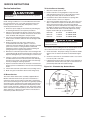
4-522.5
5H75804
October, 2010
installation and service manual
oil-fired unit heaters
model POR ➀
FOR YOUR SAFETY
The use and storage of gasoline or other
flammable vapors and liquids in open
containers in the vicinity of this appliance
is hazardous.
WARNING
Improper installation, adjustment,
alteration, service or maintenance can
cause property damage, injury or death,
and could cause exposure to substances
which have been determined by various
state agencies to cause cancer, birth
defects or other reproductive harm. Read
the installation, operating and maintenance
instructions thoroughly before installing or
servicing this equipment.
CAUTION
To prevent premature heat exchanger
failure do not locate ANY oil-fired units in
areas where chlorinated, halogenated or
acid vapors are present in the atmosphere.
IMPORTANT
The use of this manual is specifically
intended for a qualified installation and
service agency. All installation and service
of these units must be performed by a
qualified installation and service agency.
Inspection on Arrival
1. Inspect unit upon arrival. In case of damage, report
immediately to transportation company and you local Modine
sales representative.
2. Check rating plate on unit and motor to verify that power
supply and motor specification requirements meet available
electric power at the point of installation.
3. Inspect unit received for conformance with description of
product ordered (including specifications where applicable).
➀ This manual is for models with Beckett Clean Cut Burner.
FOR YOUR SAFETY
What to do if you smell gas:
1.Open windows.
2.Do not try to light any appliance.
3.Do not touch any electrical switch; do not use any phone in your building.
4.Immediately call your gas supplier.
THIS MANUAL IS THE PROPERTY OF THE OWNER.
PLEASE BE SURE TO LEAVE IT WITH the owner WHEN YOU LEAVE THE JOB.
special precautions / table of contents
Special Precautions
THE INSTALLATION AND MAINTENANCE INSTRUCTIONS
IN THIS MANUAL MUST BE FOLLOWED TO PROVIDE SAFE,
EFFICIENT AND TROUBLE-FREE OPERATION. iN ADDITION,
PARTICULAR CARE MUST BE EXERCISED REGARDING
THE SPECIAL PRECAUTIONS LISTED BELOW. FAILURE
TO PROPERLY ADDRESS THESE CRITICAL AREAS COULD
RESULT IN PROPERTY DAMAGE OR LOSS, PERSONAL
INJURY, OR DEATH. THESE INSTRUCTIONS ARE SUBJECT
TO ANY MORE RESTRICTIVE LOCAL OR NATIONAL CODES.
HAZARD INTENSITY LEVELS
1. DANGER: Indicates an imminently hazardous situation
which, if not avoided, WILL result in death or serious injury.
2. WARNING: Indicates a potentially hazardous situation which,
if not avoided, COULD result in death or serious injury.
3. CAUTION: Indicates a potentially hazardous situation which,
if not avoided, MAY result in minor or moderate injury.
4. Important: Indicates a situation which, if not avoided,
MAY result in a potential safety concern.
danger
Appliances must not be installed where they may be exposed
to a potentially explosive or flammable atmosphere.
warning
1. Oil-fired heating equipment must be vented - do not
operate unvented.
2. Disconnect power supply before making wiring connections to
prevent electrical shock and equipment damage.
3. All appliances must be wired strictly in accordance with wiring
diagram furnished with the appliance. Any wiring different
from the wiring diagram could result in a hazard to persons
and property.
4. Any original factory wiring that requires replacement must
be replaced with wiring material having a temperature
rating of at least 105°C.
5. When servicing or repairing this equipment, use only
factory-approved service replacement parts. A complete
replacement parts list may be obtained by contacting
Modine Manufacturing Company. Refer to the rating plate
on the appliance for complete appliance model number,
serial number, and company address. Any substitution of
parts or controls not approved by the factory will be at the
owner’s risk.
6. Ensure that the supply voltage to the appliance, as
indicated on the serial plate, is not more than 5% greater
than the rated voltage.
caution
2. When oil-fired unit heaters are to be installed in areas having negative pressure (for example - a space with exhaust fans) a power venter is recommended.
3. Do not install units below 7 feet, measured from the bottom of the unit to the floor, unless properly guarded to provide protection from moving parts.
4. Do not install unit heater or vent pipe closer than 18 inches to combustible materials in any direction, except the front of the unit heater, which must be unobstructed.
5. A barometric draft control must be installed on each unit heater, in the same space as the unit heater and as close to the unit as possible.
6. Verify that bypass plug is not installed in the fuel unit when
unit is connected to a one pipe oil system. Operating with
the bypass plug on a one pipe system will permanently
damage fuel unit and void warranty.
7. Do not mount the oil safety valve more than three feet
above the burner inlet or above the lowest point in fuel line
pipings between burner and Oil safety valve. In-line mounting
is recommended.
8. Start-up and adjustment procedures should be performed by a qualified oil serviceman.
9. Do not reset primary control if heat exchanger is hot. Wait
until cooled. If unit fails to operate properly after resetting
twice, consult the factory.
10.Never use a nozzle size or type other than specified in Service Instructions.
11.Do not attempt to start the burner when excess oil or oil
vapor has accumulated in the combustion chamber or
when the heat exchanger is very hot.
12.Burner adjustments should only be performed by qualified oil serviceman.
13.To prevent unusual thermal stress and eventual harm to the heat exchanger, do not operate unit heater without fire pot
or with a damaged fire pot that does not enclose the flame.
14.Do not attempt to reuse any mechanical or electrical controllers which have been wet. Replace defective controller.
15.Ensure that the supply voltage to the appliance, as indicated
on the serial plate, is not less than 5% below the rated voltage.
important
1. To prevent premature heat exchanger failure, do not locate
ANY oil-fired appliances in areas where corrosive vapors
(i.e. chlorinated, halogenated or acid) are present in the
atmosphere.
2. To check most of the Possible Remedies in the troubleshooting
guide listed in Table 18.1, refer to the applicable sections of the
manual.
Table of Contents
1.Do not locate units in tightly sealed rooms or small compartments (commonly referred to as confined spaces) without provisions for adequate combustion air and venting. Combustion air must have access to the confined space through a minimum of two permanent openings in the enclosure, at least one near the bottom. They should provide a free area of not less than one square inch per 1,000 BTU/Hr input rating of all units in the enclosure with a minimum of 100 square inches for each opening, whichever is greater.
2
caution
Inspection on Arrival . . . . . . . . . . . . . . . . . . . . . . . . . . . . . . . . 1
Special Precautions . . . . . . . . . . . . . . . . . . . . . . . . . . . . . . . . . 2
SI (Metric) Conversion Factors . . . . . . . . . . . . . . . . . . . . . . . . 3
Unit Location . . . . . . . . . . . . . . . . . . . . . . . . . . . . . . . . . . . . . . 3
Installation . . . . . . . . . . . . . . . . . . . . . . . . . . . . . . . . . . . . . . . . 4
Units/Accessories . . . . . . . . . . . . . . . . . . . . . . . . . . . . . . . . . . 9
Operation . . . . . . . . . . . . . . . . . . . . . . . . . . . . . . . . . . . . . . . . . 10
Dimensional/Performance Data . . . . . . . . . . . . . . . . . . . . . . . . 12
Service Instructions . . . . . . . . . . . . . . . . . . . . . . . . . . . . . . . . . 14
Service & Troubleshooting . . . . . . . . . . . . . . . . . . . . . . . . . . . . 18
Warranty . . . . . . . . . . . . . . . . . . . . . . . . . . . . . . . . . . Back Page
4-522.5
si (metric) conversion factors / unit location
3. In multiple unit installations, arrange units so that each
supports the air stream of the next unit, thus creating
circulatory air movement in the area. See Figure 3.1. A large
portion of the heated air should be directed toward the side
of the building exposed to prevailing winds.
SI (Metric) Conversion Factors
Table 3.1
To ConvertMultiply ByTo Obtain
"W.C.
0.24
kPa
psig
6.893
kPa
°F
(°F-32) x 0.555
°C
inches
25.4
mm
feet
0.305
meters
CFM
0.028
m3/min
To ConvertMultiply ByTo Obtain
CFH
1.699
m3/min
Btu/ft3
0.0374
mJ/m3
pound
0.453
kg
Btu/hr
0.000293
kW/hr
gallons
3.785
liters
psig
27.7
"W.C.
4. When locating units, it is important to consider that the
exhaust vent piping must be connected to the outside
atmosphere.
5. Be sure the structural support at the unit location site is
adequate to support the weight of the unit. For proper
operation the unit must be installed in a level horizontal
position.
General Information
Install and wiring of these oil-fired unit heaters must conform to
all applicable local codes, the National Electric Code, and NFPA
No. 31 “Installation of Oil Burning Equipment” by the National Fire
Protection Association. Installation of these unit heaters should
only be performed by a qualified oil serviceman.
1. These unit heaters are listed by Underwriters Laboratories,
Inc., with components as furnished.
2. Fuel oil grade No. 1 or 2, with a flash point not less than 100°F,
is approved for these unit heaters as specified by (ASTM)
D396-73 Standard Specification for Fuel Oils, or the Canadian
Government Specification Board, 3-GP-28, (American Society
for Testing and Materials).
unit location
danger
6. Do not install units in locations where the flue products
can be drawn into the adjacent building openings such as
windows, fresh air intakes, etc.
7. Be sure that the minimum clearances to combustible
materials and recommended service clearances are
maintained. Units are designed for installation on with the
minimum clearances shown in Table 3.2.
8. Do not install units in locations where the burner is exposed
to water spray, rain, or dripping water.
9. Mounting Height (measured from bottom of unit) at which
unit heaters are installed is critical. Refer to mounting height
information and heat throw data on page 12 of this manual.
The maximum mounting height for any unit is that height
above which the unit will not deliver heated air to the floor.
Figure 3.1 - Typical Unit Locations
Appliances must not be installed where they may be exposed
to potentially explosive or flammable atmosphere.
caution
1.Do not locate units in tightly sealed rooms or small compartments (commonly referred to as confined spaces) without provisions for adequate combustion air and venting. Combustion air must have access to the confined space through a minimum of two permanent openings in the enclosure, at least one near the bottom. They should provide a free area of not less than one square inch per 1,000 BTU/Hr input rating of all units in the enclosure with a minimum of 100 square inches for each opening, whichever is greater.
2.When oil-fired unit heaters are to be installed in areas having negative pressure (for example - a space with exhaust fans) a power venter is recommended.
important
Table 3.2 - Combustible Material and Service Clearances
All Model Sizes
To prevent premature heat exchanger failure, do not locate
ANY gas-fired appliances in areas where corrosive vapors (i.e.
chlorinated, halogenated or acid) are present in the atmosphere.
Location Recommendations
Top Sides
Back
Front
Bottom
Flue
18”
18”
18”
Unobstructed
18”
18”
1. When location the furnace, consider general space and
heating requirements, availability of gas and electrical
supply, and proximity to vent locations.
2. Unit heaters should be located so they discharge air nearly
parallel to exposed walls. Arrange units so they do not
blow directly at occupants. Interference of air streams by
columns, beams, partitions, or other obstructions should be
avoided as much as possible.
4-522.5
3
installation
Combustion Air Requirements
Figure 4.1 - Suspension Methods
For complete combustion, 14-1/2 lbs. of air is required for
each pound of No. 2 fuel oil. Lack of combustion air can cause
erratic burner operation, noisy combustion, fuel odors and soot
deposits on heat exchanger walls resulting in lowered efficiency
and high fuel consumption.
Units installed in tightly sealed buildings or confined spaces
must be provided with two permanent openings, one near
the top of the confined space and one near the bottom. Each
opening should have a free area of not less than one square
inch per 1,000 BTU per hour of the total input rating of all units
in the enclosure with a minimum of 100 square inches for each
opening, whichever is greater, freely communicating with interior
areas having, in turn adequate infiltration from the outside.
For further details on supplying combustion air to a confined
(tightly sealed) space or unconfined space, see the National
Fuel Gas Code ANSI Z223.1 of CAN/CGA B149.1 or .2
Installation Code, latest edition.
Venting
Confined and Unconfined Spaces
The National Fuel Gas Code defines an “unconfined space” as
a space whose volume is greater than 50 cubic feet per 1000
Btu/Hr input of the installed appliance(s). A confined space
is 50 cubic feet or less per 1000 Btu/Hr input of the installed
appliance(s).
Unit Suspension
warning
Oil-fired heating equipment must be vented - do not operate
unvented.
caution
A barometric draft control must be installed on each unit
heater, in the same space as the unit heater and as close to
the unit as possible.
caution
1. Do not install units below 7 feet, measured from the
bottom of the unit to the floor, unless properly guarded to
provide protection from moving parts.
1. To dispose of flue gasses, all oil-fired heaters must be
vented per NFPA No. 31 “Installation of Oil Burning
Equipment” and all local codes.
2. Do not install unit heater or vent pipe closer than 18
inches to combustible materials in any direction, except
the front of the unit heater, which must be unobstructed.
2. Do not install chimney connector closer than 18 inches
to combustible materials in any direction. Where chimney
connector passes through a wall or partition, a metal
ventilated thimble not less than 12 inches larger in diameter
than the connector must be used.
1. Be sure the means of suspension is adequate to support
the weight of the unit (see Table 12.1 for unit weights).
2. For proper operation, the unit must be installed in a level
horizontal position.
3. Clearances to combustibles as previously specified must be
strictly maintained.
4. It is recommended that adequate service access in access
of 18 inches be provided for the burner and fan limit switch.
5. Do not install unit heater above the maximum mounting
height shown in Table 12.2.
Four tapped holes (1/2" - 13) in the top of the unit are provided
for unit heater suspension. Suspension can be made with
threaded rods, pipes, or ceiling hanger brackets furnished by
others. See Figure 12.1 for hanger hole locations and Figure 4.1
for suspension methods.
NOTE: A pipe hanger adapter kit, shown in Figure 4.1 is
available as an accessory from Modine, or can be selffabricated. Kit consists of two drilled 3/4" I.P.S. pipe caps and
two 1/2" - 13 x 1-3/4" capscrews to facilitate threaded-pipe
suspension. Two kits are required for mounting each unit.
4
3. All Modine oil-fired heaters have an 8 inch vent connection.
Never use a chimney connector smaller than 8 inches,
except a 7 inch adapter may be used on Model POR100 to
accomodate a 7 inch vent.
4. Install a barometric draft control the same size and on
the vent pipe as close to the unit as possible. Installing a
barometric draft control is essential for proper operation
of the unit. Excessive over fire draft can cause unburned
fuel to accumulate in the stack creating a potentially
explosive condition. To install barometric draft control, refer
to instructions furnished by draft control manufacturer. The
air flow opening of the barometric draft control should face
the front of the unit heater or away from air currents in the
vicinity of the heater.
the barometric draft control must be adjusted
to provide minus 0.02 inches w.c. (water column)
overfire draft as measured between the draft
control and the unit and as close to the unit as
possible.
4-522.5
installation
Wiring
Venting - continued
5. If it is necessary to have an excessively high stack or if
the stack is located such that it is susceptible to updraft
conditions caused by wind, then oversized barometric
dampers should be installed. In extremely windy locations, a
Breidert type vent cap is recommended.
6. For the best venting, the chimney should be as close to the
unit as possible. Keep flue pipes as straight as possible,
avoiding sharp bends. Limit horizontal runs to 75% of
vertical height or a maximum of 10 feet. Horizontal runs in
excess of 10 feet require a draft booster. Chimney connector
must be pitched at a minimum upward slope of 1/4 inch per
foot.
7. Condensed flue products will cause rapid corrosion of vent
pipes and heat exchanger. Where possible, avoid venting
through unheated or unoccupied spaces. When necessary,
insulate pipe from cold to maintain draft head and prevent
condensation. Provide a drip leg with a clean-out cap at
bottom of vertical pipe. See Figure 5.1.
8. The chimney must be high enough to provide a minus 0.02
inches W.C. (water column) overfire draft. The top of the
chimney must be at least 3 feet above the highest point
where it passes through the roof and at least 2 feet higher
than any portion of a building within 10 feet of the chimney.
See Figure 5.1.
9. When connecting vent to existing chimney, do not push vent
pipe beyond internal surface of chimney.
10.If making more than one connection into the same chimney,
the chimney connectors must enter at different levels and
the area of the chimney must be equal to or greater than the
combined areas of the individual connectors.
Figure 5.1 - Typical Venting Arrangement
warning
1. Disconnect power supply before making wiring connections to
prevent electrical shock and equipment damage.
2. All appliances must be wired strictly in accordance with wiring
diagram furnished with the appliance. Any wiring different
from the wiring diagram could result in a hazard to persons
and property.
3. Any original factory wiring that requires replacement must
be replaced with wiring material having a temperature
rating of at least 105°C.
4. Ensure that the supply voltage to the appliance, as
indicated on the serial plate, is not more than 5% greater
than the rated voltage.
caution
Ensure that the supply voltage to the appliance, as indicated on
the serial plate, is not less than 5% below the rated voltage.
General
Installation of wiring must conform with local building codes,
or in the absence of local codes, with the National Electric
Code ANSI/NFPA 70 - Latest Edition. Unit must be electrically
grounded in conformance to this code. In Canada, wiring must
comply with CSA C22.1, Part 1, Electrical Code.
Unit Heater Wiring
All internal wiring to the burner motor, fan motor and the fan
and limit control has been completed at the factory. Provide
115-volt electric service from a fused disconnect switch to the
octagon junction box on the rear of the unit heater. Wire must be
insulated to 60°C and must be a minimum of 14-gauge (AWG)
copper in at least 1/2 inch thin-wall or flexible metal conduit.
Thermostat Wiring
The proper wiring for a single thermostat for each unit heater
is shown in Figure 6.1. The multiple unit wiring diagram shown
in Figure 6.2 illustrates typical wiring and connections used
with a centralized oil distribution system for multiple unit
installations. This diagram is provided as a reference only, and
is not intended to satisfy any particular local code requirements.
System operation and compliance with local codes is the
responsibility of the installer.
Figure 5.2 - Barometric Draft Control Above Unit
As shown, this system includes a relay for low voltage control
of the booster pump, and the line voltage power supply to
the booster pump motor. Figure 6.2 also shows the proper
connections for multiple unit heaters, each controlled by
a thermostat. In this arrangement, a 25V power source is
connected to pressure switches on each unit. Upon demand
for heat, a thermostat energizes the controls which start each
burner. Meanwhile, separate pressure switches, on the fuel unit,
sense an increase in oil pressure, and close their contacts to
activate the booster pump switching relay, which in turn starts
the booster pump. Optional high and low pressure controllers
can supply line pressure. Location of a remote, low-voltage
thermostat should be determined by the heating requirements
and be mounted on an inside wall approximately 5 feet above
the floor. It must not be located where it would be affected
by direct heat from the unit or other sources or drafts from
frequently opened doors or windows. See instructions packed
with thermostat. The unit may also be controlled by a remote
U.L. listed manual on-off switch.
4-522.5
5
installation
Figure 6.1 - Single Unit Wiring Diagram
115V/60HZ/1Ø
Wiring Legend
FACTORY
FIELD
WIRE NUT
FUSED DISCONNECT
SWITCH (BY OTHERS)
FAN & LIMIT
CONTROL
FAN
MOTOR
FAN LIMIT
FAN
SWITCH
BL
W
BK
BK
LIMIT
CONTROL
BURNER
MOTOR
R
GROUND
VALVE
FIELD WIRING
JUNCTION BOX
(ON HEATER)
BK
VALVE
BK
W
W
V
PRIMARY
CONTROL
T
USE COPPER
CONDUCTORS ONLY
W
OR
BK
T
VIOLET
W
IGNITOR
EQUIPMENT
GROUND
GR
BURNER
MOTOR
IGNITOR
BL/W tr
PRIMARY
CONTROL
Y
Y
LOW VOLT.
THERMOSTAT
T
LOW
VOLT.
THERM.
JUNCTION BOX
ON BURNER
Y
Y
(BY OTHERS)
BURNER HOUSING
ALL WIRING MUST CONFORM TO
NATIONAL ELECTRIC CODE NFPA #70
AND APPLICABLE LOCAL CODES
W
T
OR
CAD
CELL
V
BK
BL/W tr
BL/W tr W
GROUND
IN J-BOX
FAN
MOTOR
FIELD WIRING
CONNECTIONS
(WIRE NUTS
BY OTHERS)
CAD CELL
FUSED DISCONNECT
SWITCH (BY OTHERS)
115V/60 HZ 1Ø
Single-phase,intermittent ignition,
low voltage thermostat
5H70830B REV. B
Figure 6.2 - Typical Multiple Unit Installation and Booster Pump Wiring Diagram
115V/60HZ/1Ø
115V/60HZ/1Ø
115V/60HZ/1Ø
FUSED DISCONNECT
SWITCH (BY OTHERS)
FUSED DISCONNECT
SWITCH (BY OTHERS)
UNIT #1
115V/60HZ/1Ø
FUSED DISCONNECT
SWITCH (BY OTHERS)
UNIT #2
FIELD WIRING
JUNCTION BOX
(ON HEATER)
GROUND
PRESSURE
SWITCH
ACCESSORY
BURNER
HOUSING
GROUND
IN J-BOX
UNIT #3
FIELD WIRING
JUNCTION BOX
(ON HEATER)
T PRIMARY T
CONTROL
BURNER
MOTOR
FUSED DISCONNECT
SWITCH (BY OTHERS)
BURNER
HOUSING
PRESSURE
SWITCH
ACCESSORY
LOW VOLTAGE
T-STAT
(BY OTHERS)
FIELD WIRING
JUNCTION BOX
(ON HEATER)
GROUND
IN J-BOX
TPRIMARY T
CONTROL
PRESSURE
SWITCH
ACCESSORY
BURNER
MOTOR
LOW VOLTAGE
T-STAT
(BY OTHERS)
BURNER
HOUSING
GROUND
IN J-BOX
T PRIMARY T
CONTROL
BURNER
MOTOR
LOW VOLTAGE
T-STAT
(BY OTHERS)
R
W
25V
115V
2
W
1
3
4
BK
BOOSTER PUMP
MOTOR
(BY OTHERS)
BOOSTER PUMP RELAY - BY OTHERS
(HONEYWELL RA89A, W-R809A-3, OR EQUIVALENT)
GROUND
6
4-522.5
This diagram is provided for
reference only. System operation
and compliance with local codes is
the responsibility of the installer.
Note: All wiring shown as dashed
lines is field wiring.
installation
Piping
Piping Selection
Figure 7.1 can be used to approximate system piping
requirements for two pipe systems. Determine the total lift in
feet from the bottom of the supply tank to the fuel unit and
subtract from 20 feet. This is the reserve available in feet of oil
for piping losses. Determine the total equivalent length of piping
by adding the total straight lengths to the equivalent length
of straight pipe for each elbow and tee per Table 7.1. Locate
the point of intersection of the total equivalent length of piping
and the reserve piping loss in feet of oil on the graph. Always
use the pipe size below this point on the graph to allow for
unforeseen losses and ample reserve for filter losses.
caution
V
erify that bypass plug is not installed in the fuel unit when
unit is connected to a one pipe oil system. Operating with the
bypass plug on a one pipe system will permanently damage
fuel unit and void warranty.
1. All piping must be done in accordance with NFPA No. 31
“Installation of Oil Burning Equipment” and all local codes.
2. All piping shall be steel or brass pipe, with UL - listed fittings.
Galvanized or wrought iron pipe is not recommended. 1/2
inch O.D. copper tubing with flared fittings is recommended
for connecting the tank to the burner.
Figure 7.1 - Burner Fuel Unit Capacity
3. Protect piping from possible injury and fasten in place.
Where practicable, it should be buried underground, or
in a concrete floor, or placed in a metal-covered pipe
trench. Do not cover piping until burner has been installed
and operated so that any leaks may be corrected. Use
non-hardening pipe thread compound resistant to oil for
threaded connections
4. Refer to Figure 10.1 and 10.2 on page 10 for pump and fuel
unit components and connections.
important: all pipe and/or tube fittings on feed
line to burner must be absolutely air tight! use
only flared fittings on tubing connections. do
not use compression fittings.
Oil Tanks
To provide for a safe and continuous fuel supply, the tanks and
piping to the unit heaters must be installed in accordance with
state and local codes and must conform to applicable sections
of NFPA No. 31, “Installation of Oil Burning Equipment.”
Keep oil storage tank filled, even during summer, to prevent
condensation of water vapor. To prevent air locks, storage tank
should not be filled while units are operating. If oil tank runs dry,
it may be necessary to vent the air from lines and fuel unit when
re-starting the burner.
Single-Unit Piping
Two Pipe System
Table 7.1 - Equivalent Length of Straight Pipe or
Tubing (feet)
Fitting
3/8" O.D.
1/2" O.D.
TypeTubeTube
90° ELL
45° ELL
TEE
1.4
0.5
0.5
1/2" I.P.S.
Pipe
3/4" I.P.S
Pipe
1.7
0.8
0.7
2.1
1.0
1.1
1.4
0.5
0.5
Figure 7.2 - Two Pipe System
Modine oil-fired unit heaters are equipped with two-stage fuel
units that require an internal bypass plug (shipped loose). They
are recommended for use on two-pipe systems. (Supply and
return lines connected to fuel unit) in high lift applications, up
to 15 inches Hg (Mercury) inlet vacuum (20 foot vertical lift or
equivalent) when directly connected to a supply tank. All unit
heaters are capable of operating on two pipe systems, however,
the bypass plug must be installed if the furnace is operated on a
two pipe system. See Figure 7.2. If more than one unit is piped
to the same tank, separate suction oil lines must be installed
for each unit. A single common line, however, can be piped in
series for fuel oil return.
One Pipe System
One pipe systems are not recommended when vertical lift
exceeds 10 feet. The fuel unit is supplied with a by-pass
plug shipped loose from the factory and stored in a bag on
the fuel unit. DO NOT INSTALL THIS PLUG FOR ONE PIPE
SYSTEMS. If the fuel unit has a label stating that the by-pass
plug is installed remove the plug before starting unit. Operating
the burner on a one pipe system with the plug installed will
cause permanent damage.
4-522.5
UNIT
HEATER
SHUT-OFF
VALVE
OIL SUPPLY
LINE
FILTER
OIL RETURN
LINE
FILL
VENT
VERTICAL
LIFT
OIL TANK
NOTE: These circuits do not satisfy any particular local
code requirements. Compliance with local codes is the
responsibility of the installer.
7
INSTALLATION
Multiple Unit Supply
To save piping, oil tanks, and provide flexibility to extend pipe
supply lines to multiple-unit installations, a centralized oil
distribution system may be installed with a booster pump, oil
safety valves, and vacuum breaker. Figures 8.1 and 8.2 illustrate
typical loop and pressurized oil supply systems. In each of these
systems the unit heater is installed as in a one-pipe system.
Figure 8.1 - Typical Loop System for Multiple Units
Be sure the bypass plug is not installed in the fuel
unit when it is connected to a one-pipe oil system.
The loop system utilizes a vacuum breaker to assure an instant
supply of oil to all units. NFPA requires that oil pressure at the
fuel unit does not exceed 3 PSIG.
For multiple-unit systems, as shown in Figures 8.1 and 8.2,
install a generous-capacity oil filter in the inlet line to booster
pump suction line. Refer to Figure 6.2 for a typical wiring
diagram for multiple unit installations.
Figure 8.2 - Typical Pressurized Supply System for Multiple Units
8
4-522.5
UNIT COMPONENTS / ACCESSORIES
Figure 9.1 - Cutaway View of Oil-Fired Unit Heater
1. Combination fan-limit switch
2. Flue outlet
3. Flame inspection port cover
4. Horizontal louvers
5. Clean-out covers
6. Heat exchanger
7. Ceramic fiber fire-pot
8. Flame-retention head
9. Nozzle electrode assembly
10. Junction box
11. Burner motor and assembly
12. Finger-proof fan guard
13. Internal baffle
14. Heater fan
15. Primary control
16. Ignition Transformer
2
1
14
3
13
16
4
12
15
11
5
10
9
8
6
7
Accessories
Oil Safety Valve (OSV)
Barometric Draft Control
The Oil safety valve can be installed in any position. Preferred
position is cover up. The “IN” port is connected to the supply
line, the “OUT” port to the burner line. Do not install backwards.
Do not attach draft control to top or bottom of horizontal flue
pipe or in a room separate from unit heater. The best location
is as close to the unit heater as possible. Use a spirit level to
make sure the draft control is plumb in all directions, regardless
of whether the flue is horizontal, vertical or sloping. Refer to
venting instructions in this manual for additional information
on barometric draft controls. To install barometric draft control,
consult instructions furnished by draft control manufacturer.
caution
Do not mount the oil safety valve more than three feet above
the burner inlet or above the lowest point in fuel line pipings
between burner and oil safety valve. In-line mounting is
recommended.
Oil Filter
On all installations, install an oil filter in the supply line
immediately in front of the fuel unit. The fuel filter must always
be installed lower than the fuel unit. Piping connections are
1/4" FPT. Refer to installation instruction furnished by filter
manufacturer for more complete information.
Figure 9.2 - Barometric Draft Control and Fuel Filter
The Oil safety valve is opened by a slight vacuum appearing
at the outlet of the Oil safety valve, generated by the burner
fuel unit. Failure to observe the above caution may result in
siphoning action in the event of failure of the fuel line between
burner and Oil safety valve.
Refer to instructions furnished by valve manufacturer for
complete installation instructions. Piping connections for 3/8
inch FPT.
Pressure Switch
The pressure switch is piped to the bleed screw/pressure
port on the burner fuel unit. Suntec offers a fitting, part
number 131405, to make this installation easier and retain the
brake bleeder screw. Contact your local Suntec supplier for
availability. Its 25V contacts close, activating a booster pump
relay, when the burner starts. Consult switch manufacturer’s
instructions. Connection is 1/8 inch MPT.
Figure 9.3 - Oil Safety Valve and Pressure Switch
4-522.5
9
operation
Operating Sequence
Prior to Operation
Although this unit has been inspected and fire-tested at the
factory, the following procedures should be performed to assure
proper on-site operation:
caution
Start-up and adjustment procedures should be performed by
a qualified oil serviceman.
The operation of Modine oil-fired unit heaters is governed by a
primary control which operates the burner, and a fan and limit
switch which controls the circulating air fan dependent on the
heat exchanger temperature.
The primary control is energized when the thermostat “calls” for
heat. It starts the burner motor which turns the combustion air
blower and fuel unit. The fuel unit is a 2-stage type that draws
oil from the supply tank and delivers it at high pressure to the
burner nozzle. A valve built into the fuel unit is controlled by the
primary control and allows the motor to run for 15 seconds (prepurge) before fuel is delivered.
Combustion will be established and the heat exchanger will
begin to warm-up. When the fan and limit switch detects the
proper temperature, it will turn on the circulating air fan. The
time it takes before the circulating air fan turns on after the
burner is started is a function of the temperature setting on the
fan and limit switch.
1. Check fan clearance. 1/4 inch is allowed between fan blade
tip and venturi.
2. Check all electrical connections to be sure they are secure,
and in accordance with the wiring diagram.
3. Check firmness of unit suspension. Tighten all fasteners, if
necessary.
4. Inspect vent pipe for rigidity of mounting. Gate on
barometric draft control should operate freely.
5. Trace oil lines for closed shut-off valves or filter head
valves. Open valves as required.
6. Inspect oil supply in storage tank to assure there is
sufficient fuel.
7. Check piping components (filters, Oil safety valves, etc.) to
make sure they are installed in the proper relationship to the
direction of oil flow.
8. Check to assure good electrical contact between
transformer terminals and electrode buss bars.
Figure 10.1 - Burner Assembly with Beckett Fuel Unit
When the thermostat is satisfied, the primary control will shut off
the burner. The circulating air fan will shut off when the fan and
limit switch detects a sufficiently low temperature. The fan and
limit switch also has a manual switch which allows constant “fan
on” operations.
primary
control
reset
ignition
transformer
bleeder
valve
thermostat
terminals
Safety Devices
caution
burner
fuel unit
Do not reset primary control if heat exchanger is hot. Wait
until cooled. If unit fails to operate properly after resetting
twice, consult the factory.
The primary control is an intermittent ignition device that allows
the electrodes to spark continuously until ignition is established.
It uses the cad cell to detect the presence of a flame. Upon
start-up, if no flame is detected, the primary control will permit
the burner to run for a maximum of 15 seconds before “lockout”.
It must be manually reset before the unit can be started. If
flame signal is lost during burner operation the control will shut
down the fuel flow and, after a cool down period will attempt
to re-light. If flame is re-established the burner will continue to
operate until the call for heat ends. If flame is not established
the control will lock out.
The fan and limit switch performs the dual function of operating
the circulating air fan and turning the burner off if an overheat
condition occurs. Such a condition would exist if insufficient
circulating air is driven across the heat exchanger or if the unit
is over-fired.
oil
pressure
adjusting
screw
combustion
air shutter
burner
motor
combustion
air band
Figure 10.2 - Fuel Unit, Beckett
Solenoid
The motor for the circulating air fan has internal thermal
overload protection. If for any reason, the motor overheats,
the thermal protector will shut it off. The motor will re-start
automatically when it has cooled.
Inlet
1/4 NPT
Nozzle Port
1/8 NPT
Air Bleed Screw/
Pressure Port
Inlet
1/4 NPT
10
4-522.5
Return
1/4 NPT
operation
Initial Start-Up
1. Adjust room thermostat above room temperatures.
2. Open shut-off valves at tank and in oil supply line to the burner.
3. Turn on power to the unit. If burner does not start immediately,
push reset buttons on burner motor and primary control.
4. For units installed on a single pipe system, vent air from fuel
unit and oil supply lines immediately after the burner motor
starts. Vent air by opening bleeder valve on fuel unit until oil
appears clear (no foam), then close tightly. Ignition should
occur as soon as bleeder valve is closed.
If the air cannot be vented and ignition established within 15
seconds, the primary control will“lockout” and shut off the
burner. If this happens, wait several minutes to make sure
the heat exchanger is cool then push red reset button on
primary control. Repeat venting procedure until ignition has
been established. NOTE: Beckett primary controls have a
special "Pump Prime" mode that can be used on start up to
prevent lock out. See "Priming the Pump" in the Beckett
control literature.
For units installed on a two pipe system, venting of air from
oil lines is not necessary. However, ignition will not occur until
the air has been purged from the fuel unit and nozzle line.
This may take longer than 15 seconds and cause the primary
control to “lockout”. If this happens, wait several minutes to
make sure the heat exchanger is cool, then push red reset
button on primary control. Repeat venting procedure until
ignition has been established.
5. After ignition has been established, adjust the air bands
located on the left side of the burner to produce a #1 smoke
reading and allow the unit to run for approximately 10
minutes before making further adjustments. Then, adjust the
barometric draft control to produce a minus 0.02 inches W.C.
overfire draft. The draft reading must be taken in the flue pipe
between the barometric draft control and the unit and as
close to the unit as possible.
6. Shut unit off and connect a pressure gauge to the pressure
gauge port on the fuel unit. When the unit is turned on, the
pressure should be 130 +/- 2psi for POR100 and 145, 100 +/2psi for POR 185. If pressure adjustment is necessary, adjust
pressure with screwdriver or Allen wrench. See Figure 10.2.
7. After the oil pressure is set, readjust the air bands to produce
just a trace of smoke which is slightly less than #1. From the
trace point, open the air bands to give 0 (zero) smoke. A
carbon dioxide (CO2) check at this smoke level should read
11.5 to 12.5%. CO2 levels above 12.5% are not recommended
as sooting could occur as conditions and fuel vary.
8. The fan and limit switch is factory set at a high limit
temperature of 210°F. Do not change this setting. It is also
factory set to turn on the fan at 120°F and turn it off at 90°F.
These settings may be changed by following the control
manufacturer’s instructions packed in the literature envelope
attached to the unit. Since the fan and limit control is
operated by a thermal switch, not the thermostat, residual
heat in the heat exchanger can cycle the fan on after the
thermostat has been satisfied.
9. Adjust the air deflector blades for desired heat distribution. All
horizontal blades should be kept open a minimum of 30° as
measured from vertical.
10.Run the unit through several cycles by raising and lowering
the thermostat setting to assure proper sequence of operation.
4-522.5
11
DIMENSIONS / PERFORMANCE DATA
Figure 12.1 - Oil-Fired Unit Heater Dimensions
Table 12.1 - Outline Dimensions (inches)
Approx.
Shipping
ModelABCDEFG
H
J
KLMY
Wt. Lbs.
POR 100
POR 145
27-1/2
27-1/2
35-1/4
35-1/4
28-1/8
28-1/8
25
25
23-7/8
23-7/8
13-3/4
13-3/4
8-5/8
8-5/8
23-7/8
23-7/8
8
9-1/2
POR 185
28-5/8
40-1/4
32-3/4
26-1/8
23-7/8
14-3/8
8-5/8
25
10
12
12
38-1/8
38-1/8
13-3/4 42-3/4
16
16
8
8
324
333
20-3/4
8
398
Table 12.2 - Performance Data
Model
Input
(Btu/Hr)
Output
(Btu/Hr)
CFM
@70°F
Temp
Rise
(°F)
GPH
Max
Mtg Ht
(ft)
Heat
Throw
(ft)
Motor
HP
Supply
Voltage
(V/Hz/ph)
Fan
Motor
Amps
RPM
Motor
Type
Fan
Dia.
POR100
119,000
100,000
1890
POR145
175,000
145,000
2400
49
0
12
39
1/5
115/60/1
2
1100
PSC
18”
56
1
14
50
1/3
115/60/1
5
1100
PSC
18”
POR185
231,000
185,000
3200
54
2
12
51
1/3
115/60/1
5
1100
PSC
22”
*Deflector blades pitch 45° toward the floor. (Heated air). Mounting heights measured from floor to bottom of unit.
The maximum mounting height is that height above which the unit will not deliver heated air to the floor.
*Total amps equals fan motor amps plus burner and ignition transformer load of 5.8 amps.
12
4-522.5
this page intentionally left blank
4-522.5
13
service instructions
Service Instructions
To Service Burner Assembly
1. Disconnect electric power to unit.
caution
2. Remove fasteners on hinged ignitior on top of the unit
and swing back giving access to the inside of the burner
housing, the nozzle, cad cell, and blower wheel.
Service procedures should only be performed by a qualified
oil serviceman.
3. Clean blower wheel and combustion air openings with
vacuum cleaner or air hose, if required.
Routine Unit Maintenance
4. The nozzle should be replaced every year, more often if it is
dirty or carbonized. To replace nozzle disconnect external
oil line at the burner housing, then remove the drawer
assembly (nozzle line and electrode assembly) locknut from
the fitting. Lift drawer assembly up and out of the air blast
tube. Do not disturb drawer assembly adjustment setting.
Replace nozzle with type as specified below:
Under average conditions, it is recommended that unit heaters
be serviced at least once a year and checked out prior to the
heating season. In excessively dirty atmospheres, service
should be performed more often.
1. Disconnect power supply to the unit before performing any
of following maintenance of inspection procedures.
2. Tighten fan guard and motor bracket. Check fan for proper
clearance, free rotation, and firm connection to motor shaft.
Clean fan blade with detergent or compressed air.
3. Fan motor is permanently lubricated for normal operation.
Under severe conditions, lubricate with non-detergent SAE
20 motor oil.
4. Routine cleaning of the unit casing and louvers is
recommended to remove dirt, grease, or corrosive
substances that may damage the finish. Rusted or corroded
spots on the louvers or casing should be sanded and
repainted. To remove, push louvers against retaining coil
spring and pull out at opposite tapered end.
POR 100
0.75 GPH
70° solid cone
POR 145
1.10 GPH
70° solid cone
POR 185
1.65 GPH
70° solid cone
caution
Never use a nozzle size or type other than specified in
Service Instructions.
Use extreme care in handling nozzles to avoid scratches or dirt
that could cause leaks or affect the oil spray pattern.
5. With louvers removed inspect inside of heat exchanger with
a flash light through the flame inspection port. Check for soot
deposits, damaged fire pot, heat exchanger or burner head.
5. Check electrodes. The proper setting is essential for reliable
ignition of the oil. Set the electrodes as illustrated in Figure
14.1.
6. If there is a heavy soot-coating inside heat exchanger, it
should be drawn out with a vacuum cleaner after removing
the front access panel. Care must be taken not to damage
the fire pot during the cleaning operation.
6. Check the cad cell for an accumulation of dirt or soot. Clean
if necessary with a soft cloth.
7. Replace fuel oil filter elements at unit heater and at booster
pump to prevent contamination of the fuel unit and atomizing
nozzle.
7. Lubricate burner motor with a few drops of non-detergent oil
at both motor oil holes twice each year on units that are not
permanently lubricated with sealed bearings.
Figure 14.1 - Electrode Gap, Beckett Burner
8. Check entire electrical system before every heating season.
9. Make sure gate on barometric draft control swings freely.
Oil Burner Service
5/32" gap
The electric motor-driven burner assembly supplied with the
Modine oil-fired unit heaters lifts, pressures and atomizes a
continuous charge of fuel oil with a forced draft of combustion
air into the heat exchanger fire pot where it is ignited by sparking
electrodes. Burner components that will require inspection and
service include the burner motor, blower wheel primary control,
nozzle, nozzle, electrodes, and the fuel unit. The burners utilize
either a Honeywell, or Beckett primary control and cad cell and
either a Beckett or a Suntec fuel unit. Refer to manufacturer’s
instructions packed with each unit.
electrode
5/16" above cL
nozzle
1/16"
14
4-522.5
service instructions
Burner Adjustments
F. Test the flue gas for carbon dioxide (CO2) content. Zero
the CO2 analyzer and insert probe into flue pipe and draw
sample of the flue gas into analyzer. The concentration of
CO2 should be 11.5 to 12.5%. CO2 levels above 12.5% are
not recommended as sooting could occur as conditions and
fuel vary at zero smoke.
caution
1. Do not attempt to start the burner when excess oil or oil
vapor has accumulated in the combustion chamber or
when the heat exchanger is very hot.
G. Conclude testing by reading stack temperature and subtract
room temperature to get the net stack temperature. Using
this figure and the CO2 reading, use the slide calculator
provided with the CO2 analyzer to compute steady-state
efficiency. Efficiencies of 80% should be attainable.
2. Burner adjustments should only be performed by
qualified oil serviceman.
3. Do not attempt to view the flame while starting the
burner, since pulsations which sometimes occur upon
start-up can discharge hot gases through the inspection
port.
Primary Control Service
It is recommended that a combustion check be made on the
burner each year or whenever replacing a nozzle. This will help
assure efficient combustion of the oil and avoid sooting the heat
exchanger.
The flame can be viewed through the inspection port located
on the front of the heat exchanger. DO no attempt to
view the flame while starting the burner,
since pulsations which sometimes occur upon
start-up can discharge hot gases through the
inspection port.
The primary control (see Figure 10.1) is not intended to be
serviced in the field. Replace defective controls. It senses
ignition failure and flame failure and can be checked by a
relatively simple procedure. Start the unit.
a. Simulate flame failure by removing one cad cell lead from
the F terminal of primary control with burner on. Fifteen
seconds after flame extinguishes, primary control will lock
out and stop burner motor and ignition spark. Attach the
cad cell lead to the F terminal. Reset safety switch on top of
primary control after test.
The best adjusted flame pattern will be a clean, yellow,
solid cone which is well established on the burner head and
terminates into short licks of flame within the ceramic fiber
fire pot.
caution
Do not reset primary control if heat exchanger is hot. Wait
until cooled. If unit fails to operate properly after resetting
twice, consult the factory.
An accurate combustion check can only be made with the
proper instrumentation as described below.
A. Install a pressure gauge on the pressure gauge port of the
fuel unit. Start burner and adjust oil pressure to 130 +/- 2psi
for POR100 and 145, 100 +/- 2psi for POR 185. See Item 6
- Initial Start-Up.
B. Make two holes about 1/4 inch in diameter in the flue
pipe about 6 inches above the flue connection but below
barometric draft control. Two openings permit taking the
stack temperature in one, while the second opening is used
to conduct draft test, and carbon dioxide (CO2) test. Close
openings with sheet metal screws after tests have been
completed.
C. Insert stem of stack thermometer in one opening while
performing other tests.
D. Allow burner to operate approximately 5 minutes before
taking any readings. To measure draft, place draft gauge
on any level surface adjacent to the unit heater and adjust
it to zero. Draft gauge should read minus 0.02 inches W.C.
minimum. Draft can be changed by adjusting the weight
on the barometric draft control. Improper draft can cause
erratic and incomplete combustion which will result in noisy
operation, soot deposits, excessive smoke and fuel oil
odors.
If operation is not as described and wiring is in accordance with
diagram on page 6, refer to cad cell service before replacing
primary control.
Cad Cell Service
Under normal operating conditions the cad cell does not require
cleaning. Small accumulations on the surface of the cell will
not affect its operation. However, if a badly adjusted burner
has caused heavy accumulation of soot, the surface should be
wiped carefully to remove all opaque substances and restore
full view of the oil flame.
If cad cell should ever be damaged, the cell may be removed by
simply unplugging it from the socket assembly. Avoid disturbing
the positioning of the socket assembly. Replace the damaged
cell.
Figure 15.1 - Cad Cell
E. The smoke tester measures smoke content of flue gas
and is prepared by inserting a strip of clean filter paper in
the slot provided. Insert probe into flue and pump smoke
tester ten strokes to draw a sample of flue gas through the
filter paper. Filter paper should be removed and compared
against the standard Bacharach smoke scale which has
ten graded color spots from white (O smoke) to the darkest
shade of gray. To adjust the combustion air, loosen the
locknut for the combustion air bands on the side of the
burner and rotate the bands slightly until a #0 to #1 smoke
reading is achieved. Increasing the air opening will lighten
the smoke spot and decreasing the air openings will darken
it. Tighten locknut and recheck reading.
4-522.5
15
service instructions
Fuel Unit Service
Fire Pot Service
A Beckett two stage, 3450 RPM fuel unit is supplied on all
Modine oil unit heaters. Two stage fuel units are intended for
high lift applications, up to 15 inches Hg. (Mercury) of inlet
vacuum or the equivalent of 20 feet of vertical lift. For high
lift applications, it is recommended that a two pipe oil supply
system be used. Burners are shipped with the bypass plug
removed. This plug must be installed for such applications.
The ceramic-fiber fire pot will seldom, if ever, require
replacement unless it is accidentally damaged during a heat
exchanger cleaning operation. To replace, take off the front
access panel and remove all fire pot pieces. Carefully insert
new fire pot with the enclosed corbeled end to be opposite the
burner nozzle. (Open end of fire pot must be toward nozzle.)
Do not install the plug for single pipe applications. Fuel
unit damage will result.
The Beckett fuel unit utilizes an internal strainer to trap foreign
material. Periodically, remove the fuel unit cover and clean
the strainer with a brush and clean fuel oil. Generally, service
problems do not occur with a fuel unit. A thorough check should
be made before replacing any fuel unit.
caution
To prevent unusual thermal stress and eventual harm to the
heat exchanger, do not operate unit heater without fire pot
or with a damaged fire pot that does not enclose the flame.
Figure 16.1 - Ceramic-Fiber Fire Pot
A. Install a vacuum gauge on an unused inlet port, when the
unit is turned on, the gauge should read approximately 1
inch of vacuum for each foot of vertical lift. Gravity fed fuel
units should read zero vacuum. If reading is higher than
expected, check for a closed tank or supply valve, kinked
tubing, plugged filter or strainer, frozen oil line, undersized
oil line or excessive oil lift, if gauge reads below expected
vacuum, look for air leaks in the oil hinges, valves, fittings or
fuel unit.
B. Install a pressure gauge on the gauge port of the fuel unit.
Pressure should read 130 +/- 2psi for POR100 and 145,
100 +/- 2psi for POR 185. If adjustment is necessary, refer
to Item 6 - Initial Start-Up. If needle on gauge bounces, see
service diagnosis for remedy.
C. To check the fuel unit cut-off pressure, install a pressure
gauge in the nozzle port. Operate the unit for approximately
one minute, then shut the unit off. The pressure should read
130 +/- 2psi for POR100 and 145, 100 +/- 2psi for POR
185 while the unit is running and should not drop to less
than 80 PSI and hold there after the burner is shut off. If the
pressure drops to zero, the fuel unit should be replaced.
Replacement Parts
All replacement parts and controls are proprietary in that they
have all been designed, tested, and approved for the particular
application to insure both physical and electrical fit and
performance. Any substitution of parts or controls not approved
by Modine will be at customer’s risk.
NOTE: Modine Manufacturing Company reserves the
right to substitute parts of advanced design and to change
specifications or prices without advance notice or without
incurring obligations.
Replacement parts can be obtained by submitting the model
number, power code, control code, and serial number shown
on the rating plate attached to the unit, along with a description
of the part, to the Service Department, Modine Manufacturing
Company, West Kingston, RI 02892.
16
4-522.5
this page intentionally left blank
4-522.5
17
service & troubleshooting
warning
When servicing or repairing this equipment, use only
factory-approved service replacement parts. A complete
replacement parts list may be obtained by contacting Modine
Manufacturing Company. Refer to the rating plate on the
appliance for complete appliance model number, serial
number, and company address. Any substitution of parts or
controls not approved by the factory will be at the owner’s risk.
Table 18.1 - Troubleshooting
caution
Do not attempt to reuse any mechanical or electrical
controllers which have been wet. Replace defective controller.
important
To check most of the Possible Remedies in the troubleshooting
guide listed in Table 18.1, refer to the applicable sections of
the manual.
Remedy
Problem A. Unit does not operate.
1. No oil. 1. Fill oil tank or open supply valve or check filter.
2. Electric circuit in open position. 2. a. Turn on switch or thermostat.
b. Move thermostat to higher setting.
c. Replace fuse or reset disconnect switch.
3. Blown fuses. 3. Replace fuses.
4. Burner motor runs but no spark. 4. Check electrode spacing or replace ignitor.
5. Defective or incorrect wiring. 5. Check wiring and connections. Refer to diagram.
6. Defective thermostat or switch. 6. Check continuity with volt-ohmmeter. Replace defective part if necessary.
7. Primary control locked out on safety. 7. Push reset button on primary control only if heat exchanger is cool. Try this only twice.
See control service instructions.
8. Defective cad cell. 8. Replace cad cell if necessary. Check continuity.
9. Burner or fan motor out on overload. 9. Check voltage wiring and motor. Reset overload button on burner motor. Fan motor automatically reset.
Problem B. Unit starts and shuts off.
1. Clogged nozzle. 1. Replace nozzle.
2. Air leaks in suction line. 2. Tighten all fittings.
3. Faulty ignition. 3. a. Reset electrodes in burner assembly. Check insulators.
b. Check wiring at primary control.
c. Replace ignitor, if required.
4. High draft, too much air. 4. Check draft regulator adjustment. Adjust combustion air openings on burner.
5. Improper oil pressure. 5. Adjust fuel pump with pressure and vacuum gauges.
Problem C. Fan operates but burner does not operate.
1. Manual fan switch is on. 1. Turn off manual fan switch.
2. See burner service diagnosis. 2. See burner service diagnosis.
3. See fuel pump service diagnosis. 3. See fuel pump service diagnosis.
Problem D. Burner operates but fan does not operate.
1. Fan motor failure. 1. a. Check for loose electrical connections. Check wiring with diagram on rear of heater.
b. Repair or replace burned out or defective motor.
c. Voltage too high or too low. Check voltage with voltmeter.
2. Loose fan. 2. Tighten fan set screw.
3. Defective fan switch in fan limit control. 3. Replace entire control.
4. Defective or incorrect wiring. 4. Check all wiring and connections. See diagram on rear casing panel.
Problem E. Insufficient heat.
1. Too few units for heat loss. 1. Add more units or use larger size units.
2. Unit mounted too high. 2. Lower units.
3. Fan operates backwards. 3. Replace motor.
Problem F. Loud noise during starting.
1. Water in oil. 1. Bleed line at fuel unit. Replace supply if necessary
2. Delayed ignition. 2. a. Reset electrode gaps.
b. Nozzle worn or dirty. Replace nozzle.
c. Check voltage drop when burner motor starts. High current draw can result in weak spark from transformer.
d. Inspect ignitor and wiring.
e. Check to assure positive contact between transformer terminals and electrode buss bars.
Problem G. Fuel oil odors.
1. Oil or air leak in supply system. 1. Tighten all fittings and check for leaking supply valve stems.
2. Down draft blowing out of barometric 2. a. Check for blocked chimney or vents.
regulator.
b. Check regulator setting and adust to correct.
3. Improper flame adjustment. 3. Inspect flame through inspection port. Adjust burner air openings and/or fuel oil pressure.
4. Delayed ignition. 4. See F-2.
5. In adequate combustion air/ventilation. 5. See recommendations for outdoor air openings. Page 4.
Oil Burner Assembly
Remedy
Problem A. Burner motor does not start.
1. Incomplete electrical circuit. 1. Check main disconnect switch, fuses, thermostat contacts, and operating and limit controls.
2. Primary control locked out on safety. 2. Wait five minutes and until heat exchanger is cool. Actuate external reset on relay. Determine cause for lock-out and correct.
3. Motor bearings frozen. 3. Free shaft and lubricate.
4. Motor off/on thermoprotector. 4. Allow motor to cool and push reset button. If motor cuts out again, check wiring to locate cause.
18
4-522.5
service & troubleshooting
Oil Burner Assembly (Continued)
Remedy
Problem B. Burner motor operates but no oil delivered at nozzle.
1. Oil level below intake line inside supply tank. 1. Fill tank with oil and bleed air from the line.
2. Clogged strainer. 2. Remove and clean strainer.
3. Clogged nozzle. 3. Remove and clean or replace nozzle.
4. Air leak in the intake line. 4. Tighten all fittings in the intake line. Tighten unused intake port plug in the fuel unit. If there are valves in the line, be sure the valve stems are packed solid and tightened securely.
5. Restricted intake lines (high vacuum). 5. Replace any kinked tubing and check all valves in the intake line.
6. A two pipe system that becomes air bound. 6. Insert by-pass plug if not in place. Prime pump.
7. A single pipe system that becomes air bound. 7. See start-up procedure.
8. Slipping or broken coupling. 8. Tighten or replace coupling.
9. Frozen fuel unit shaft. 9. Return unit to factory.
10. Excessive vacuum.
10. Use next larger tubing size. Too high of a lift. Also see B5.
11. Dirty oil filter cartridge.
11. Replace cartridge.
Problem C. Burner motor operates, delivers oil, but no flame.
1. No spark. 1. Check the ignitor and high tension insulators.
2. Poor atomization of oil. 2. Adjust oil pressure to 130 +/- 2psi for POR100 and 145, 100 +/- 2psi for POR 185, check for oil line restriction and nozzle defects.
3. Improper electrode setting. 3. Remove firing assembly and adjust.
4. Excessive combustion air. 4. See start-up procedure.
Problem D. Burner starts but flame blows away from nozzle.
1. Excessive combustion air. 1. See start-up procedure.
2. Excessive draft. 2. Adjust draft regulator.
3. Poor atomization of oil. 3. Change nozzle with same capacity.
4. Uneven flame. 4. Change nozzle with same capacity.
Burner Fuel Unit
Remedy
Problem A. No oil flow at nozzle.
1. Oil level below intake line in supply tank. 1. Fill tank with oil. (Bleed air from oil lines.)
2. Clogged strainer or filter. 2. Remove and clean strainer. Replace filter element.
3. Clogged nozzle. 3. Replace nozzle.
4. Air leak in intake line. 4. Tighten all fittings in intake line. Tighten unused intake port plug. Check filter cover and gasket.
5. Restricted intake line (high vacuum reading). 5. Replace any kinked tubing and check any valves in intake line. Check for correct line sizes.
6. A two-pipe system that becomes air bound. 6. Check for and insert by-pass plug. Make sure return line is below oil level in tank.
7. A single-pipe system that becomes air bound. 7. Loosen gauge port plug or easy flow valve and bleed oil for 15 seconds after foam is gone in bleed hose. Check intake line fittings for tightness. Check all pump plugs for tightness.
8. Slipping or broken coupling. 8. Tighten or replace coupling.
9. Rotation of motor and fuel unit is not the same 9. Install fuel unit with correct rotation.
as indicated by arrow on pad at top of unit.
10. Frozen fuel unit shaft.
10. Return unit to approved service station or factory for repair. Check for water and dirt in tank.
Problem B. Oil leak.
1. Loose plugs or fittings. 1. Dope with good quality oil-resistant thread sealer. Retighten.
2. Leak at pressure adj. screw or nozzle plug. 2. Washer may be damaged. Replace washer or O-ring.
3. Blown seal (single-pipe system). 3. Check if by-pass plug has been left in unit. Replace fuel unit.
4. Blown seal (two-pipe system). 4. Check for kinked tubing or other obstructions in return line. Replace fuel unit.
5. Seal leaking. 5. Replace fuel unit.
6. Cover loose. 6. Tighten cover screws or replace damaged gasket.
Problem C. Noisy operation.
1. Bad coupling alignment. 1. Loosen fuel unit mounting screws slightly and shift unit in different positions until noise is eliminated. Retighten mounting screws.
2. Air in inlet line. 2. Check all connections. Use only good flare fittings.
3. Tank hum on two-pipe system and inside tank. 3. Install hum eliminator in return line.
Problem D. Pulsating pressure.
1. Partially clogged strainer or filter. 1. Remove and clean strainer. Replace filter element.
2. Air leak in intake line. 2. Tighten all fittings.
3. Air leaking around cover. 3. Be sure strainer cover screws are tightened securely. Check for damaged cover gasket.
4. High vacuum. Should not exceed 17 inches 4. Closed shut-off valve, clogged filter, kinked tubing, too small on line.
Hg (mercury).
Problem E. Low oil pressure.
1. Defective gauge. 1. Check gauge against master gauge, or other gauge.
Problem F. Improper nozzle cut-off.
1. Filter leaks. 1. Check face of cover and gasket for damage.
2. Strainer cover loose. 2. Tighten screws on cover.
3. Air pocket cut-off valve and nozzle. 3. Run burner, stopping and starting unit, until smoke and after-fire disappears.
4. Air leak in intake line. 4. Tighten intake fittings. Tighten unused intake port and return plug.
5. Partially clogged nozzle strainer. 5. Clean strainer or change nozzle.
6. Leak at nozzle adaptor. 6. Change nozzle and adaptor.
4-522.5
19
commercial Warranty
Seller warrants its products to be free from defects in material and
workmanship, EXCLUSIVE, HOWEVER, of failures attributable to the use
of materials substituted under emergency conditions for materials normally
employed. This warranty covers replacement of any parts furnished from the
factory of Seller, but does not cover labor of any kind and materials not
furnished by Seller, or any charges for any such labor or materials, whether
such labor, materials or charges thereon are due to replacement of parts,
adjustments, repairs, or any other work done. This warranty does not apply to
any equipment which shall have been repaired or altered outside the factory of
Seller in any way so as, in the judgment of Seller, to affect its stability, nor
which has been subjected to misuse, negligence, or operating conditions in
excess of those for which such equipment was designed. This warranty does
not cover the effects of physical or chemical properties of water or steam or
other liquids or gases used in the equipment.
BUYER AGREES THAT SELLER’S WARRANTY OF ITS PRODUCTS TO BE
FREE FROM DEFECT IN MATERIAL AND WORKMANSHIP, AS LIMITED
HEREIN, SHALL BE IN LIEU OF AND EXCLUSIVE OF ALL OTHER
WARRANTIES, EITHER EXPRESS OR IMPLIED, WHETHER ARISING
FROM LAW, COURSE OF DEALING, USAGE OF TRADE, OR OTHERWISE,
THERE ARE NO OTHER WARRANTIES, INCLUDING WARRANTY OF
MERCHANTABILITY OR FITNESS FOR PURPOSE, WHICH EXTEND
BEYOND THE PRODUCT DESCRIPTION CONFIRMED BY BUYER AND
SELLER AS OF THE DATE OF FINAL AGREEMENT.
This warranty is void if the input to the product exceeds the rated input as
indicated on the product serial plate by more than 5% on gas-fired and oil-fired
units, or if the product in the judgment of SELLER has been installed in a
corrosive atmosphere, or subjected to corrosive fluids or gases, been subjected
to misuse, negligence, accident, excessive thermal shock, excessive humidity,
physical damage, impact, abrasion, unauthorized alterations, or operation
contrary to SELLER’S printed instructions, or if the serial number has been
altered, defaced or removed.
BUYER AGREES THAT IN NO EVENT WILL SELLER BE LIABLE FOR
COSTS OF PROCESSING, LOST PROFITS, INJURY TO GOODWILL, OR
ANY OTHER CONSEQUENTIAL OR INCIDENTAL DAMAGES OF ANY KIND
RESULTING FROM THE ORDER OR USE OF ITS PRODUCT, WHETHER
ARISING FROM BREACH OF WARRANTY, NONCONFORMITY TO
ORDERED SPECIFICATIONS, DELAY IN DELIVERY, OR ANY LOSS
SUSTAINED BY THE BUYER.
Component
Applicable Models
Heat Exchangers
Gas-Fired Units except PSH/BSH
Heat Exchangers
Low Intensity Infrared Units
Compressors
Condensing Units for Cassettes
Burners
Low Intensity Infrared Units
Other
Components excluding Heat Exchangers,
Coils, Condensers, Burners, Sheet Metal
BUYER’S REMEDY FOR BREACH OF WARRANTY, EXCLUSIVE OF ALL
OTHER REMEDIES PROVIDED BY LAW, IS LIMITED TO REPAIR OR
REPLACEMENT AT THE FACTORY OF SELLER, ANY COMPONENT WHICH
SHALL, WITHIN THE APPLICABLE WARRANTY PERIOD DEFINED HEREIN
AND UPON PRIOR WRITTEN APPROVAL, BE RETURNED TO SELLER
WITH TRANSPORTATION CHARGES PREPAID AND WHICH THE
EXAMINATION OF SELLER SHALL DISCLOSE TO HAVE BEEN DEFECTIVE;
EXCEPT THAT WHEN THE PRODUCT IS TO BE USED BY BUYER AS A
COMPONENT PART OF EQUIPMENT MANUFACTURED BY BUYER,
BUYER’S REMEDY FOR BREACH, AS LIMITED HEREIN, SHALL BE
LIMITED TO ONE YEAR FROM DATE OF SHIPMENT FROM SELLER. FOR
GAS-FIRED PRODUCTS INSTALLED IN HIGH HUMIDITY APPLICATIONS
AND UTILIZING STAINLESS STEEL HEAT EXCHANGERS, BUYER’S
REMEDY FOR BREACH, AS LIMITED HEREIN, SHALL BE LIMITED TO
TEN YEARS FROM DATE OF SHIPMENT FROM SELLER.
These warranties are issued only to the original owner-user and cannot be
transferred or assigned. No provision is made in these warranties for any
labor allowance or field labor participation. Seller will not honor any expenses
incurred in its behalf with regard to repairs to any of Seller’s products. No
credit shall be issued for any defective part returned without proper written
authorization (including, but not limited to, model number, serial number,
date of failure, etc.) and freight prepaid.
OPTIONAL SUPPLEMENTAL WARRANTY
Provided a supplemental warranty has been purchased, Seller extends the
warranty herein for an additional four (4) years on certain compressors.
Provided a supplemental warranty has been purchased, Seller extends the
warranty herein for an additional four (4) years or nine (9) years on certain
heat exchangers.
EXCLUSION OF CONSUMABLES & CONDITIONS BEYOND SELLER’S
CONTROL
This warranty shall not be applicable to any of the following items: refrigerant
gas, belts, filters, fuses and other items consumed or worn out by normal wear
and tear or conditions beyond Seller’s control, including (without limitation as
to generality) polluted or contaminated or foreign matter contained in the air or
water utilized for heat exchanger (condenser) cooling or if the failure of the part
is caused by improper air or water supply, or improper or incorrect sizing of
power supply.
“APPLICABLE WARRANTY PERIOD”
TEN YEARS FROM DATE OF FIRST BENEFICIAL USE BY BUYER OR ANY OTHER USER, WITHIN
TEN YEARS FROM DATE OF RESALE BY BUYER OR ANY OTHER USER, WITHIN TEN YEARS
FROM DATE OF RESALE BY BUYER IN ANY UNCHANGED CONDITION, OR WITHIN ONE
HUNDRED TWENTY-SIX MONTHS FROM DATE OF SHIPMENT FROM SELLER, WHICHEVER
OCCURS FIRST
FIVE YEARS FROM DATE OF FIRST BENEFICIAL USE BY BUYER OR ANY OTHER USER, WITHIN
FIVE YEARS FROM DATE OF RESALE BY BUYER OR ANY OTHER USER, WITHIN FIVE YEARS
FROM DATE OF RESALE BY BUYER IN ANY UNCHANGED CONDITION, OR WITHIN SIXTY-SIX
MONTHS FROM DATE OF SHIPMENT FROM SELLER, WHICHEVER OCCURS FIRST
TWO YEARS FROM DATE OF FIRST BENEFICIAL USE BY BUYER OR ANY OTHER USER, WITHIN
TWO YEARS FROM DATE OF RESALE BY BUYER IN ANY UNCHANGED CONDITION, OR WITHIN
THIRTY MONTHS FROM DATE OF SHIPMENT FROM SELLER, WHICHEVER OCCURS FIRST
Heat Exchangers/Coils
Indoor and Outdoor Duct Furnaces and
System Units, PSH/BSH, Steam/Hot Water Units,
Oil-Fired Units, Electric Units, Cassettes,
Vertical Unit Ventilators
Compressors
Vertical Unit Ventilators
ONE YEAR FROM DATE OF FIRST BENEFICIAL USE BY BUYER OR ANY OTHER USER, WITHIN
ONE YEAR FROM DATE OF RESALE BY BUYER IN ANY UNCHANGED CONDITION, OR WITHIN
EIGHTEEN MONTHS FROM DATE OF SHIPMENT FROM SELLER, WHICHEVER OCCURS FIRST
Burners
High Intensity Infrared Units
Sheet Metal Parts
All Products
As Modine Manufacturing Company has a continuous product improvement program, it reserves the right to change design and specifications without notice.
© Modine Manufacturing Company 2010
Commercial Products Group
Modine Manufacturing Company
1500 DeKoven Avenue
Racine, WI 53403
Phone: 1.800.828.4328 (HEAT)
www.modinehvac.com