1
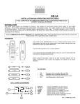
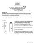
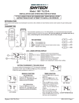
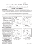
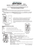
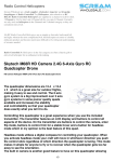
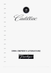
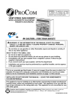
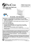
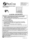
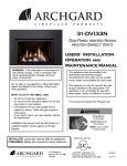
CON 1001TH-1
(SKY CON TH-1)
INSTALLATION AND OPERATING INSTRUCTIONS
MULIT-FUNCTION WIRELESS REMOTE CONTROL SYSTEM
FOR OPERATING A LATCHING SOLENOID VALVE, MANUALLY OR WITH A THERMOSTAT FUCTION
IF YOU CANNOT READ OR UNDERSTAND THESE INSTALLATION INSTRUCTIONS DO NOT
ATTEMPT TO INSTALL OR OPERATE
INTRODUCTION
This remote control system was developed to provide a safe, reliable, and user-friendly remote control system for gas heating
appliances. The system is operated manually from the transmitter. The system operates on radio frequencies (RF) within a 20-feet
range using non-directional signals. The system operates on one of 1,048,576 security codes that are programmed into the transmitter
at the factory; the remote receiver's code must be matched to that of the transmitter prior to initial use.
Review COMMUNICATION SAFETY under GENERAL INFORMATION section. This safety feature shuts down
the appliance when a potentially unsafe condition exists.
TRANSMITTER
This remote control SYSTEM offers the user a battery-operated remote control to
power a latching solenoids such as those used with gas valves used in some
heater rated gas logs, gas fireplaces and other gas heating appliances.
WALL CLIP
SLOT
ON
BUTTON
ON
The solenoid circuit uses the battery power from the receiver to operate a
solenoid. The circuit has reversing polarity software which reverses the positive
(+) and negative (-) output of the receiver's battery power to drive a latching
solenoid ON/OFF. The SYSTEM is controlled by the remote transmitter.
MODE
BUTTON
OFF
MODE
OFF
BUTTON
SET
The transmitter operates on a (2) 1.5V AAA batteries.
SET
BUTTON
It is recommended that ALKALINE batteries always be used for longer battery life
and maximum operational performance.
BATTERY
COMPARTMENT
FRONT
ON
Before using the transmitter, install the (2) AAA transmitter batteries into the
battery compartment. (Use caution that batteries are installed in the proper
direction)
BACK
1
KEY SETINGS
OFF
2
MODE
3
SET
4
ON
OFF
MODE
SET
- Operates unit to on position, Manually operated solenoid ON.
- Operates unit to off position, Manually operated solenoid OFF.
- Changes unit from manual mode to thermo mode.
- Sets temperature in thermo mode.
___________________________________________________________________________________________________________
Skytech CON 1001TH-1
REV. 5/17/11 Page 1 of 6
LCD - Liquid Crystal Display
2
1
3
4
ROOM
SET TEMP
5
1.
2.
3.
4.
5.
6.
DISPLAY
0
0
F OR C
FLAME
ROOM
TEMP
SET
temperature in
Indicates CURRENT room temperature .
Indicates degrees Fahrenheit or Celsius.
Indicates burner/valve in operation.
Indicates remote is in THERMO operation.
Appears during manual operation.
Appears during time the of setting the desired
the thermo operation.
6
0
0
SETTING F / C SCALE
0
0
The factory setting for temperature is F. To change this setting to C,
first
•
TEMP
Press the ON key and the OFF key on the transmitter at the same
0F
0C
time this will change from
to . Follow this same procedure to
0
0
change from C back to F.
MANUAL FUNCTION
To operate the system in the manual “MODE” do the following.
TEMP
SCREEN WHILE
DEPRESSING ON
KEY
SCREEN AFTER 3
SECOND DEFAULT
ON OPERATION
Press the ON key the appliance flame will come on. During this time the
LCD screen will show ON, after 3 seconds the LCD screen will default
to display room temperature and the word TEMP will show. (Flame icon
wil appear on LCD screen in manual on mode)
OFF OPERATION
TEMP
SCREEN WHILE
DEPRESSING OFF
KEY
Press the OFF key the appliance flame will shut off. During this time the
LCD screen will show OF, after 3 seconds the LCD screen will default to
display room temperature and the word TEMP will show.
SCREEN AFTER 3
SECOND DEFAULT
THERMOSTAT FUNCTION
SETTING DESIRED ROOM TEMPERATURE
This remote control system can be thermostatically controlled when the
transmitter is in the THERMO mode (The word ROOM must be
displayed on the screen). To set the THERMO MODE and DESIRED
room temperature,
SET TEMP
THERMO SET
ROOM
TEMP
THERMO MODE
Press the MODE key until the LCD screen shows the word ROOM, then
the remote is in the thermostatic mode.
Press and hold the SET key until the desired set temperature is
reached. (By pressing and holding the set key the LCD screen set
0
0
0
numbers will increase from 45 to 99 then restart over at 45 ) Next
___________________________________________________________________________________________________________
Skytech CON 1001TH-1
REV. 5/17/11 Page 2 of 6
release the SET key. The LCD screen will display the set temperature
for 3 seconds and the LCD screen will flash the set temperature for 3
seconds, then the LCD screen will default to display the room
temperature.
TO CHANGE THE SET TEMPERATURE
ROOM
TEMP
THERMO ON
ROOM
TEMP
THERMO OFF
Press and hold the SET key until the desired set temperature is
reached. (By pressing and holding the set key the LCD screen set
0
0
0
numbers will increase from 45 to 99 then restart over at 45 ) Next
release the SET key. The LCD screen will display the set temperature
for 3 seconds, then will flash the set temperature for 3 seconds, then the
LCD screen will default to display the room temperature.
Press the MODE key to disengage the thermo mode. The word ROOM
on the LCD screen will not show when the thermo is not in operation.
0
0
NOTE: The highest SET temperature is 99 Fahrenheit (32 Celsius)
0
0
and the lowest temperature is (45 Fahrenheit (6 Celsius)
OPERATIONAL NOTES:
The Thermo Feature on the transmitter operates the appliance whenever the ROOM TEMPERATURE varies a certain number of
degrees from the SET TEMPERATURE. This variation is called the “SWING” or TEMPERATURE DIFFERENTIAL. The normal
operating cycle of an appliance may be 2-4 times per hour depending on how well the room or home is insulated from the cold or drafts.
0
0
The factory setting for the “swing number” is 2. This represents a temperature variation of +/- 2 F (1 C) between SET temperature
and ROOM temperature, which determines when the fireplace will be activated.
The transmitter has ON and OFF manual functions that are activated by pressing either button on the face of the transmitter. When a
button on the transmitter is pressed the word ON or OF will appear on the LCD screen to show while the signal is being sent. Upon
initial use, there may be a delay of three seconds before the remote receiver will respond to the transmitter. This is part of the system's
design.
POWER SETTING – CON 1001 TH
The electronics in the remote control system have the capability of "powering" two different types of DC-powered components. If any
operational problems are noted, contact Skytech Systems, Inc.
The RECEIVER comes from the factory programmed to provide pulse DC voltage (5.5 VDC to 6.3 VDC) to a latching solenoid.
REMOTE RECEIVER
IMPORTANT
THE REMOTE RECEIVER SHOULD BE POSITIONED WHERE AMBIENT
TEMPERATURES DO NOT EXCEED 130° F.
The remote receiver (right) operates on four 1.5V AA-size batteries. It is
recommended that ALKALINE batteries be used for longer battery life and maximum
microprocessor performance. IMPORTANT: New or fully charged batteries are
essential to proper operation of the remote receiver as a latching solenoid power
consumption is substantially higher than standard remote control systems.
NOTE: The remote receiver will only respond to the transmitter when the 3-position
slide button on the remote receiver is in the REMOTE position. The remote receiver
houses the microprocessor that responds to commands from the transmitter to
control system operation.
___________________________________________________________________________________________________________
Skytech CON 1001TH-1
REV. 5/17/11 Page 3 of 6
FUNCTIONS:
•
•
•
•
•
•
With the slide switch in the REMOTE position, the system will only operate
if the remote receiver receives commands from the transmitter.
Upon initial use or after an extended period of no use, the ON button may
have to be pressed for up to three seconds before activating servo motor. If
the system does not respond to the transmitter on initial use, see
LEARNING TRANSMITTER TO RECEIVER.
With the slide switch in the ON position you can manually turn ON the
system.
With the slide in the OFF position, the system is OFF.
It is suggested that the slide switch be placed in the OFF position if you will
be away from your home for an extended period of time.
Placing the slide switch in the OFF position also functions as a
safety "lock out" by both turning the system OFF and rendering the
transmitter inoperative.
INSTALLATION INSTRUCTIONS
WARNING
DO NOT CONNECT REMOTE RECEIVER DIRECTLY TO 110-120VAC POWER. THIS WILL BURN
OUT THE RECEIVER. FOLLOW INSTRUCTIONS FROM MANUFACTURER OF GAS VALVE FOR
CORRECT WIRING PROCEDURES. IMPROPER INSTALLATION OF ELECTRIC COMPONENTS
CAN CAUSE DAMAGE TO GAS VALVE AND REMOTE RECEIVER.
INSTALLATION
The remote receiver can be mounted on or near the fireplace hearth. PROTECTION FROM EXTREME HEAT IS VERY IMPORTANT.
Like any piece of electronic equipment, the remote receiver should be kept away from temperatures exceeding 130º F inside the
receiver case. Battery life is also significantly shortened if batteries are exposed to high temperatures.
HEARTH MOUNT
The remote receiver can be placed on the fireplace hearth or under the fireplace, behind the
control access panel. Position where the ambient temperature inside the receiver case does not
exceed 130º F. NOTE: Black Button is used on Hearth Mount Applications.
WIRING INSTRUCTIONS
Make sure the remote receiver switch is in the OFF position. For best results it is recommended
that 18 gauge stranded wires should be used to make connections and no longer than 20-feet.
Pulse Connection
This CON 1001 TH remote receiver is to be connected
to a manual valve with a latching ON/OFF solenoid.
Concentric Valve
PULSE MODE
Terminals
Connect two 18 gauge stranded or solid wires from the
remote receiver terminals to the latching solenoid.
(See figure to the right)
Black Wire
Red Wire
IMPORTANT NOTE: Operation of this control is
dependent on which wire is attached to which terminal.
If operation of control does not correspond to operating
buttons on transmitter, reverse wire installation at the
receiver or at the control.
Receiver
Slide
Button
LEARN
OFF
REMOTE
ON
Remote Receiver
___________________________________________________________________________________________________________
Skytech CON 1001TH-1
REV. 5/17/11 Page 4 of 6
NOTE: Up to 6.3 VDC of power is provided at the
receiver terminal.
GENERAL INFORMATION
COMMUNICATION – SAFETY – TRANSMITTER – (C/S – TX)
This SKYTECH remote control has a COMMUNICATION –SAFETY function built into its software. It provides an extra margin of safety
when the TRANSMITTER is out of the normal 20 foot operating range of the receiver.
The COMMUNICATION – SAFETY feature operates in the following manner, in all OPERATING MODES – ON/ ON THERMO.
At all times and in all OPERATING MODES, the transmitter sends an RF signal every fifteen (15) minutes, to the receiver, indicating
that the transmitter is within the normal operating range of 20 feet. Should the receiver NOT receive a transmitter signal every 15
minutes, the IC software, in the RECEIVER, will begin a 2-HOUR (120-minute) countdown timing function. If during this 2-hour period,
the receiver does not receive a signal from the transmitter, the receiver will shut down the appliance being controlled by the receiver.
The RECEIVER will then emit a series of rapid “beeps” for a period of 10 seconds. Then after 10 seconds of rapid beeping, the
RECEIVER will continue to emit a single “beep” every 4 seconds until a transmitter ON or MODE Button is pressed to reset the
receiver. The intermittent 4-second beeping will go on for as long as the receiver’s batteries last which could be in excess of one year.
To “reset” the RECEIVER and operate the appliance, you must press the ON or MODE button on the transmitter. By turning the
system to ON, the COMMUNICATION -SAFETY operation is overridden and the system will return to normal operation depending on
the MODE selected at the transmitter. The COMMUNICATION – SAFETY feature will reactivate should the transmitter be taken out of
the normal operating range or should the transmitter’s batteries fail or be removed.
CP (CHILDPROOF) FEATURE
This SKYTECH remote control includes a CHILDPROOF “LOCK-OUT” feature that allows the user to “LOCK-OUT” operation of the
appliance, from the TRANSMITTER.
SETTING “LOCK-OUT” –(CP)
•
•
•
To activate the “LOCK-OUT” feature, press and hold the ON button and the MODE button at the same time for 5 seconds. The
letters CP will appear in the TEMP frame on the LCD screen.
To disengage the “LOCK-OUT”, press and hold the ON button and the MODE button at the same time for 5 seconds and the letters
CP will disappear from the LCD screen and the transmitter will return to its normal operating condition.
To verify that transmitter is in the CP lock-out mode press any key and the LCD screen will show “CP”
NOTE: If the appliance is already operating in the ON or THERMO MODES, engaging the “LOCK-OUT” will not cancel the operating
MODE. Engaging the “LOCK-OUT” prevents only the manual operation of the TRANSMITTER. If in the auto modes, the THERMO
operation will continue to operate normally. To totally “LOCK-OUT” the operation of the TRANSMITTER’S operating signals; the
transmitter’s MODE must be set to OFF.
LEARNING TRANSMITTER TO RECEIVER
Each transmitter uses a unique security code. It will be necessary to press the LEARN button on the receiver to accept the transmitter
security code upon initial use, if batteries are replaced, or if a replacement transmitter is purchased from your dealer or the factory. In
order for the receiver to accept the transmitter security code, be sure the slide button on the receiver is in the REMOTE position; the
receiver will not LEARN if the slide switch is in the ON or OFF position. The LEARN button in located on the front face of the receiver;
inside the small hole labeled LEARN. Using a small screwdriver or end of a paperclip gently press and release the black LEARN button
inside the hole. When you release the LEARN button the receiver will emit an audible “beep”. After the receiver emits the beep press
the transmitter ANY button and release. The receiver will emit several beeps indicating that the transmitter’s code has been accepted
into the receiver.
The microprocessor that controls the security code matching procedure is controlled by a timing function. If you are unsuccessful in
matching the security code on the first attempt, wait 1 - 2 minutes before trying again--this delay allows the microprocessor to reset its
timer circuitry--and try up to two or three more times.
___________________________________________________________________________________________________________
Skytech CON 1001TH-1
REV. 5/17/11 Page 5 of 6
TRANSMITTER WALL CLIP
The transmitter can be hung on a wall using the clip provided. If the clip is
installed on a solid wood wall, drill 1/8" pilot holes and install with the screws
provided. If it is installed on a plaster/wallboard wall, first drill two 1/4" holes into
the wall. Then use a hammer to tap in the two plastic wall anchors flush with the
wall; then install the screws provided.
WALL CLIP
SLOT
WALL CLIP
BATTERY
COMPARTMENT
BATTERY LIFE
Life expectancy of the alkaline batteries in the CON 1001 TH can be up to 12 months depending on use of the solenoid function.
Replace all batteries annually. When the transmitter no longer operates the remote receiver from a distance it did previously (i.e., the
transmitter's range has decreased) or the remote receiver does not function at all, the batteries should be checked. It is important that
the remote receiver batteries are fully charged, providing combined output voltage of at least 5.5volts. The transmitter should operate
with as little as 2.5 volts battery power.
TROUBLE SHOOTING
If you encounter problems with your fireplace system, the problem may be the fireplace itself or it could be with the CON 1001 TH-1
remote system. Review the fireplace manufacturer's operation manual to make sure all connections are properly made. Then check
the operation of the remote in the following manner:
•
•
•
•
•
•
Make sure the batteries are correctly installed in the RECEIVER. One reversed battery will keep receiver from operating properly.
Check battery in TRANSMITTER to ensure contacts are touching (+) and (-) ends of battery. Bend metal contacts in for tighter fit.
Be sure RECEIVER and TRANSMITTER is within 20 to 25-feet operating range.
Clear Codes: Memory in the receiver might be full if the learn button is pressed too many times. If this happens it will not allow any
more codes to be learned and no audible beep will be heard. To clear memory, place the receiver slide switch into the REMOTE
position. Press the learn button and release after 10 seconds. You should hear three (3) long audible beeps indicating all codes
have cleared. You can now “learn” the transmitter to the receiver as described in the General Information Section.
Keep RECEIVER from temperatures exceeding 130° F. Battery life shortened when ambient temperatures are above 115° F.
If RECEIVER is installed in tightly enclosed metal surround, the operating distance will be shortened.
SPECIFICATIONS
BATTERIES:
Transmitter (2) 1.5 volt AAA t bateries
Remote Receiver 6V - 4 ea. AA 1.5 Alkaline
Operating Frequency: 303.8 MHZ
FCC ID No.'s: transmitter - K9LSP1001TH; receiver - K9L330IRX
Canadian IC ID No.'s: transmitter – 2439A-SP1001TH; receiver – 2439A-3301RX
FCC REQUIREMENTS
NOTE: THE MANUFACTURER IS NOT RESPONSIBLE FOR ANY RADIO OR TV INTERFERENCE CAUSED BY
UNAUTHORIZED MODIFICATIONS TO THIS EQUIPMENT. SUCH MODIFICATIONS COULD VOID THE USER’S
AUTHORITY TO OPERATE THE EQUIPMENT.
FOR TECHNICAL SERVICE, CALL:
U. S. INQUIRIES
CANADIAN INQUIRIES
888/672-8929 or
877/472-3923
260/459-1703
WEBSITE: skytechsystem.com
MANUFACTURED EXCLUSIVELY FOR SKYTECH II, INC.
___________________________________________________________________________________________________________
Skytech CON 1001TH-1
REV. 5/17/11 Page 6 of 6
Limited Lifetime Warranty
SKYTECH II warrants the SKYTECH REMOTE CONTROL SYSTEM for a Limited Lifetime of the original
owner of this system. This warranty is not transferable to another person it is for the original purchaser of the
product. Should any part fail because of defective workmanship or material from the original date of purchase.
SKYTECH II will repair or, at SKYTECH II option, replace the defective parts.
Replacement parts will be available at no charge for the first (5) five years of this warranty, and will be
available at market cost for the Lifetime of the product to that original owner. If SKYTECH II does not have the
parts for an individual model, then a replacement SYSTEM will be provided. At no charge for the first (5) five
years and sold at market cost for the Lifetime of that product to the original owner.
The Owner must provide a bill of sale, cancelled check, or payment record should be kept to verify purchase
date and establish warranty period. Travel, diagnostic cost, service labor to repair the defective SYSTEM, and
freight charges on warranty parts to and from the factory will be the responsibility of the owner. SKYTECH will
not be responsible for labor charges and/or damage incurred in installation, repair, replacement, or for
incidental or consequential damages. Batteries and any damage caused by them are not covered by them are
not covered by this warranty.
This warranty does not cover claims, which do not involve defective workmanship or materials.
Damage to the SYSTEM caused by accident, misuse, abuse, or installation error, whether performed by a
contractor, Service Company, or owner, is not covered by this warranty. Modification of the SKYTECH product
will void this warranty.
IN NO EVENT SHALL SKYTECH BE LIABLE FOR INCIDENTAL AND CONSEQUENTIAL INCLUDING THE IMPLIED
WARRANTIES OF MERCHANTABILITY AND FITNESS, ARE LIMITED TO THE DURATION OF THIS WRITTEN
WARRANTY. THIS WARRANTY SUPERSEDES ALL OTHER ORAL OR WRITTEN WARRANTIES.
Some States do not allow the exclusion or limitation of incidental and consequential damages or limitation on
how long an implied warranty lasts, so the above limitation may not apply to you. This warranty gives you
specific rights and you may have other rights, which vary from state, province, and nation.
How to Obtain Service:
Contact SKYTECH II or your SKYTECH Dealer direct with the following information:
Name, Address, Telephone Number of Owner
Date of Purchase, Proof of Purchase
Model Name, Date Code
Any relevant information or circumstances, e.g., installation, mode of operation when defect was noted.
Warranty claim process will start with all of this information. SKYTECH will reserve the right to physically
inspect the product for defects, by authorized representatives.
Detach at this line for return to: Skytech II 9230 Conservation Way, Fort Wayne, IN 46809 Telephone: (888) 672-8929
Purchase Date:
Model:
Purchased From:
Customer
Name
Date Code:
Date:
Number of Santa’s Helpers
Address
City
Credit Card Number
(Visa and MasterCard Only)
State/Prov.
Zip/Postal Code
Expiring Date
See other side for a special offer for all Remote control Customers
Santa’s Helper
Exclusive offer to Skytech Remote Control Owners
This special offer is only provided to customers of Skytech II, Inc. that have purchased a remote control for
their Hearth Product. This remote control system can be used for any 110Volt appliance, but perfect your
Christmas Tree Lights or any other appliance that is difficult to reach or plug in. Simply plug the receiver into
your wall outlet and your appliance into the receiver, push the ON button on the transmitter and you are in
business. It’s that easy.
The list price of $29.95 for the Santa’s Helper has been cut almost in half to $15.00 USD for this exclusive
offer. Shipping and handling of $5.00 $USD should be added. Send your check, money order or your Visa /
MasterCard number, with Expiration Date to our office, along with the warranty information from your remote
control for your Hearth Product. You can send this via mail, fax, or e-mail.
Skytech II, Inc.
9230 Conservation Way
Fort Wayne, IN
46809
1 (888) 672-8929
1 (888) 672-8024 Fax
[email protected] e-mail