1
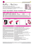
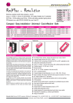
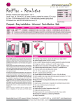
RedMax-...-Y
RedMax-...-YF
Special options
... -CTS
... -VAS
E X P L O S I O N P R O O F
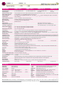
Electrical connection
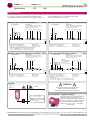
Modulating / 3-pos. – with / without spring return
24...240 VAC/ DC
−
+
~
~
2
3
UmA UVDC
YmA YVDC
5
1
2
3
4
5
6
PA
Selection of running time for spring return:
Reverse function:
Spring return in ~ 10 s = Standard wiring
Bridge 3 –4 reverses the
Spring return in ~ 3 s = Additional wiring on terminal 5
input and output signals
Function and enforcement control of switch a and b in modulating mode:
▪ a closed – Forced-ON (OFF) in acc. to left/right mounting of actuator
▪ b closed – Forced-OFF (ON) in acc. to left/right mounting of actuator
Modulating – with / without spring return (no feedback)
24...240 VAC/ DC
+
−
~
~
1
2
3
SB 5.2
T
4
UmA UVDC
5
1
2
3
Selection of running time for spring return:
Spring return in ~ 10 s = Standard wiring
Spring return in ~ 3 s = Additional wiring on terminal 5
5
6
Reverse function:
Bridge 3 – 4 reverses
the input signals
PA
a
1
2
3
b
4
Y:
U:
0...10 V / 4...20 mA
0...10 V / 4...20 mA
5
6
PA
SB 5.3
1
2
VDC/mA
3
4
UmA UVDC
5
6
PA
Attention
!
During commissioning apply a self adjustment drive.
Regard duty cycle at motor running times !
Never use spring return actuators without external load.
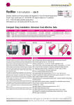
Accessory RedBox – adaptable terminal box
supply *
24...240 VAC/DC ± 10 %
RedBox
4
Reverse function:
Bridge 3 – 4 reverses the
input and output signals
Attention !
When changing 3-position
mode into modulating
regard function, see
page 4 – Parametrisation D)
5
!
Safe area
3
Selection of running time for spring return:
Reverse function:
Spring return in ~ 10 s = Standard wiring
Bridge 3 – 4 reverses
Spring return in ~ 3 s = Additional wiring on terminal 5
the output signals
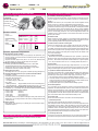
3-pos. control mode:
▪ a closed, b open – ON (OFF) in acc. to left /right mounting of actuator
▪ b closed, a open – OFF (ON) in acc. to left /right mounting of actuator
Installation
Ex area –
zone 2, 22
2
Self adjustment:
To adjust the signal input /output to the angle of
rotation of the damper / valve the button (T) must
be pushed for a minimum of 3 sec.
VDC/mA
4
1
3-pos. – with / without spring return + feedback
PE
3
5
24...240 VAC / DC
+
−
~
~
PE
2
4
Selection of running time for spring return:
Spring return in ~ 10 s = Standard wiring
Spring return in ~ 3 s = Additional wiring on terminal 5
Self adjustment:
To adjust the signal input / output to the angle of
rotation of the damper/valve the button (T) must
be pushed for a minimum of 3 sec.
YmA YVDC
1
VDC/mA
PE
b
4
Self adjustment:
To adjust the signal input / output to the angle of
rotation of the damper /valve the button (T) must
be pushed for a minimum of 3 sec.
T
1
T
a
VDC/mA
Modulating – with / without spring return (no enforcement) SB 5.1
24...240 VAC / DC
−
+
~
~
Self adjustment:
To adjust the signal input /output to the angle of
rotation of the damper /valve the button (T) must
be pushed for a minimum of 3 sec.
YmA YVDC
PE
SB 5.0
For electrical connection inside hazardous areas a terminal box is required (e.g. RedBox).
An over-current protection fuse < 10 A has to be provided by installer.
Note: the initial current is appr. 2 A for 1 second.
T
All actuators are equipped with a universal supply unit working at a voltage range from
24...240 VAC/DC. The supply unit is self adjusting to the connected voltage !
The safety operation of the spring return function works if the supply voltage is cut.
* electrical wiring see diagrams
For electrical connection of ...Max actuators inside the
hazardous area an Ex-e terminal box is required.
RedBoxes are appropriate terminal boxes and placed at
the disposal. To adapt the ...Box directly to the actuator
housing a mounting bracket type MKK-S is required.
RedBox- Y/S for ...Max-...-Y and ...-YF with integral
auxiliary switches
RedMax-S-Y_en
V01 – 4-Feb-2015
Schischek GmbH Germany, Muehlsteig 45, Gewerbegebiet Sued 5, 90579 Langenzenn, Tel. +49 9101 9081-0, Fax +49 9101 9081-77, E-Mail [email protected]
www.schischek.com
3/4