1
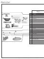
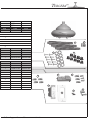
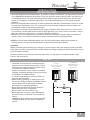
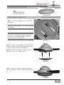
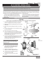
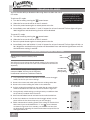
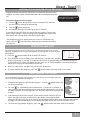
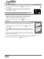
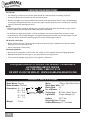
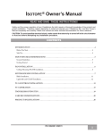
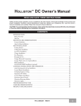
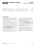
Tercera™ Owner’s Manual READ AND SAVE THESE INSTRUCTIONS! Safety and the proper operation of your Casablanca fan both require a thorough knowledge of the product and proper installation; therefore, before attempting to install and operate your Casablanca fan, read this owner’s manual completely and carefully. Retain this manual for future reference. CAUTION: To avoid possible electrical shock, make certain that electricity is turned off at the circuit breaker or fuse box before attempting any installation procedure. CONTENTS Introduction________________________________________________________________________5 Before You Start................................................................................................................................................. 5 Safe Use............................................................................................................................................................. 5 Mounting Recommendations........................................................................................................................... 6 Sloped Ceiling Installation................................................................................................................................ 6 Fan Installation_____________________________________________________________________7 Getting Started................................................................................................................................................... 7 Mounting Bracket Installation........................................................................................................................... 7 Fan Preparation.................................................................................................................................................. 8 Hanging the Fan................................................................................................................................................10 Wiring................................................................................................................................................................ 11 Securing the Canopy........................................................................................................................................13 Blade Installation..............................................................................................................................................14 Light Installation...............................................................................................................................................15 W-74 Wall Control Preparation.........................................................................................................................16 W-74 Control Installation__________________________________________________________ 17 Installing the W-74 Wall Control.......................................................................................................................17 Single W-74 Installation....................................................................................................................................17 Dual W-74 Installation.......................................................................................................................................18 W-74 Operation___________________________________________________________________ 19 Operation Power...............................................................................................................................................19 Operation Speed Control.................................................................................................................................19 Operation Reversing Airflow...........................................................................................................................19 Operation Lights...............................................................................................................................................19 Changing Frequency Setting.......................................................................................................................... 20 Operation CFL Mode....................................................................................................................................... 20 Automatic Demonstration Program............................................................................................................... 21 Operation Safe-Exit®....................................................................................................................................... 21 Light-minder® Program.................................................................................................................................. 21 Operation Fan-Minder™ Program.................................................................................................................. 22 Operation Home-Safe® Program.................................................................................................................. 22 Troubleshooting Tips______________________________________________________________ 23 Care Recommendations___________________________________________________________ 24 Product Specifications____________________________________________________________ 24 P/N C2243001 RL0610 1 Parts List Parts List 24 20 23 25 22 21 26 4 5 11 12 25 9 Item # # Item Name Name 1 Hanging System 25 Canopy 23 Screw, 10-32 24 Ceiling Plate 26 Trim Ring 20 Screw, Wood # 10 21 Screw, Wood # 8 22 Washer 4 Hanger Pipe 5 Adapter Cover 6 Blade Set 8 Hardware Pack B 7 Grommets 24 Set Screw (pre-installed) 9 Glass Assembly 11 Screw Driver Phillips 12 50W Halogen Bulb 25 Balancing Kit 10 Receiver 17 Wire Nut (Small) 17 Wire Nut (Large) 11 Wall Control Assembly 12 W74 Single Control 13 Décor Wall Plate (White) 14 Wire Nut 15 Screw 6-32 X .75 16 Screw 6-32 If you are in need of service parts, do not return this fan to the store. Tercera™ Model # C22G11L C22G45L Asm. Dwg. # G0671-01 G0671-02 Finish Snow White Brushed Nickel Qnty Qnty 1 Part #Part # 99614-03-000 Part # 99614-05-000 1 4 1 1 2 6 2 24 4 1 87942-25-203 87942-04-214 1 77364-01-000 77364-02-000 1 G0113-28-000 G0113-29-000 1 89440-15-000 89440-15-000 1 G0156-01-000 G0156-01-000 1 89122-03-000 89122-04-000 1 66282-01-133 66282-01-133 2 63852-05-000 63852-05-000 1 65520-01-000 65520-01-000 1 89346-01-000 89346-01-000 8 7 1 3 3 1 89350-01-000 89350-01-000 17 10 14 1 1 4 2 12 2 13 Call our Support Center toll free at 1-888-227-2178 15 16 PLEASE INSPECT ALL PACKAGING PRIOR TO DISCARDING! Your Casablanca fan was crafted with pride and care and inspected thoroughly prior to shipment. Before you begin to assemble and install your Casablanca fan, remove all parts from the carton and check them against the Parts Guide in this manual. Make sure all parts are included in the box using the Parts Guide on the following pages. If there are missing or broken parts: Call 1-888-227-2178 Monday through Friday, 7 a.m. to 4 p.m. PST. Your request will be handled immediately. Replacement parts will be sent to you via Federal Express. Always turn power to the ceiling fan OFF before replacing lightbulbs or working on your fan. Proper Parts Handling Never install a fan over a pool or spa. Do not remove lightbulbs from their packaging until you are ready to install them. Never operate a fan that has been damaged in any way. Before discarding packaging materials, be certain that all parts have been removed. Install the fan according to the instructions in this manual. Use a clean, dry paintbrush to remove small Styrofoam pieces that may remain after unpacking. If the fan does not work: Do not brush Styrofoam into wiring cavities. The blades in each pack are matched for equal weight to assure smooth fan operation. If more than one fan is being installed, do not mix blades from different cartons. When cleaning, painting, or working near your fan, be cautious of the fan and blades. Never insert anything into the path of the fan blades while the fan is in operation. Refer to the Troubleshooting Tips in this Owner’s Manual. Call Technical Support at 1-888-227-2178. Contact your local Authorized Service Center. Our Web site at www.casablancafanco.com contains additional information on Casablanca products, troubleshooting, and Authorized Dealer or Service Centers. Please do not return this product to the store. RECORD MODEL AND SERIAL NUMBERS BEFORE INSTALLATION! Please take a moment to locate the model number and serial number from your fan (see below) and record this information on the Warranty page inside the front cover of your Owner’s Manual if it does not appear there already. These numbers are found on the motor identification plate affixed to the fan motor in the location shown below: Motor Identification Plate Tercera TYPE HANGER TYPE Memphis, TN SERIAL No.: DJ06 2237 C22GxxL 4 DJ01 1151 MODEL C22GxxxL Serial Number Model Number Tercera™ INTRODUCTION BEFORE YOU START • CAUTION: RISK OF ELECTRICAL SHOCK! Installation is to be in accordance with the National Electrical Code, ANSI/NFPA 70-1999 and local codes. If you are unfamiliar with the wiring codes, you should use a qualified electrician. To avoid overheating and possible damage to other equipment, do not install control to a receptacle, fluorescent light fixture, motor-operated appliance, or transformer-supplied appliance. • This fan is designed to be installed on an existing electrical outlet box. The outlet box must be UL Listed for ceiling fan installations. If it is not, a new box must be installed. Casablanca extension poles are available for sloped or high ceiling installations. • This ceiling fan requires a grounded electrical supply of 120 VAC, 60 Hz and a minimum 15 amp circuit. The maximum current requirement for the fan with light fixture is 2 amps. The fan uses about 1 amp or 100 watts. Maximum light current is 1 amps or 100 watts of lighting. • Where wire nuts are employed, be sure all bare wires are within the connectors. When installing the canopy, make sure all wires are within the canopy and that no wires are being pinched. WARNING: Do not bend the blade brackets when installing the brackets, balancing the blades, or cleaning the fan. Do not insert foreign objects in between the rotating fan blades. Unpacking Before assembling and installing your ceiling fan, remove all parts from the shipping cartons and check them against the parts listed in the Parts Guide. Before discarding packaging materials, be certain that all parts have been removed. For best performance and for your warranty to be valid, use only genuine Casablanca blades, light fixtures, and accessories. SAFE USE • The blades in each pack are matched for equal weight to assure smooth fan operation. If more than one fan is being installed, be careful not to mix blades from different cartons. • Inspect the contents of your carton for possible shipping or handling damage. If parts are missing or damaged, call 1-888-227-2178. • It is always a good idea to have an assistant to help with the installation. • When cleaning, painting, or working near your fan, be very careful of the fan and blades. Always turn the power OFF to the ceiling fan before working on it or replacing lightbulbs. • Never insert anything into the path of the fan blades while the fan is in operation. • Never install a fan over a pool or spa. • Never operate a fan that has been damaged in any way. Contact Casablanca Fan Company by calling 1-888-227-2178, or contact your local authorized Casablanca dealer for assistance in obtaining service. Fuse Box (Remove fuse for the circuit you will be working on) Circuit Breaker (Trip breaker for the circuit you will be working on) 18" 70" 84" 5 MOUNTING RECOMMENDATIONS Before mounting your Casablanca fan, read the following helpful recommendations. The location of the fan, air circulation, and fan size are all important factors to consider before installation. Location Ceiling fans have practical uses in almost every room in your home. We suggest you follow these mounting recommendations as you decide where to install your Casablanca fan. • For safety reasons, the fan blades must be a minimum of 7' above the floor. • Do not locate the fan in a doorway or above a swinging door. • In bedrooms, fans work best when mounted above the foot of the bed. • Over pool tables, be sure to provide plenty of clearance to avoid damage from pool cues. • In kitchens be sure to allow for open cupboard doors to clear the fan blades. • Do not install a fan close to or over a pool or spa. High humidity combined with corrosive gases will destroy the finish and warp the blades. Fan Size Variable fan speed capability permits the use of a full-size 52" fan even in smaller rooms. For very large rooms, two fans may be needed. SLOPED CEILING INSTALLATION Suggested Extension Pole Lengths Ceiling Height 8' 0" 8' 6" 9' 0" 9' 6" 10' 0" 11' 0" 12' 0" 13' 0" 14' 0" Pole Length 3.5" 3.5" 12" 12" 18" 24" 36" 48" 60" Extension Pole Maximum ® angle 32º Blades must be a minimum of 7 feet above the floor 7' minimum When to Use Extension Poles For optimum performance and appearance, an extension pole should be used with your Casablanca fan when installing on high (cathedral) ceilings or sloped ceilings. Casablanca offers standard poles in increments of 6" up to 5'. Custom poles are available in lengths up to 9'9". See your Authorized Casablanca Dealer for details. Note: Fan may wobble or vibrate if pole length is not long enough and inside blade is too close to downslope or side wall. Extending pole length will usually solve problem. Calculation of Ceiling Angle Use the tear-off Ceiling Angle Template card inserted in this manual. It provides you with a simple “go” or “no-go” for installing your fan on a sloped ceiling. 6 EXAMPLE 1 EXAMPLE 2 EXAMPLE 3 This slope is less than 32º. It is OK to install your fan. This slope is 32º. This is the maximum slope that will allow the fan to hang straight down. It is OK to install your fan. This slope is more than 32º. Your fan will not hang straight down, an adaptor is necessary. Contact your local Authorized Casablanca Dealer in regards to purchasing a “Sloped Ceiling Adaptor.” Tercera™ FAN INSTALLATION GETTING STARTED Installing a New Ceiling Fixture Outlet Box If you do not have an existing fixture located where you wish to place your Casablanca fan, an approved ceiling fixture outlet box must be installed and wired. WARNING! To reduce the risk of fire, electrical shock, or personal injury, mount to outlet box marked “Acceptable Fan Support of 22.7 kg (50 lbs.) or less” using the mounting hardware provided with the outlet box or directly to structure. Using Existing Ceiling Fixture Outlet Box After turning the power OFF at its source (either the circuit breaker or fuse box), lower the old fixture and disconnect the wiring. Check the ceiling fixture outlet box to be sure it is marked “Approved for Ceiling Fan Mounting.” If it is not, a new box must be installed. Note: The weight of this fan is 27 pounds. MOUNTING BRACKET INSTALLATION CEILING HARDWARE (not to scale) Mounting Bracket #8 Wood Screw and Washer (2) #10 Wood Screw (2) Note: After removing the old fixture, check the outlet box to insure that it is supported by a joist or beam across its upper surface. If not, a 2 x4 stud must be installed. Step 1. Drill two pilot holes into the wood support structure through the outermost holes in the outlet box. The pilot holes should be 9/64” in diameter. Step 2. Thread the lead wires from the outlet box down through the hole in the middle of the ceiling plate. WARNING! Support directly to building structure only. 7 MOUNTING BRACKET INSTALLATION (CONT.) Step 1. Align the slotted holes in the ceiling plate with the pilot holes you drilled in the wood support structure. For proper alignment use slotted holes directly across from each other. Joist Note: The isolators should be flush against the ceiling. Step 2. Place a flat washer on each of the two 3” wood screws and pass the screws through the slotted holes in the ceiling plate into the pilot holes you drilled. Ceiling Fan Approved Wiring Box Washer Wood Screw Step 3. Tighten the screws into the 9/64” pilot holes; do not use lubricants on the screws. Do not over tighten. Note: On sloped ceilings, align the canopy opening toward the top or peak of the room. PREPARATION HARDWARE SET SCREW (pre-installed) Hanging Adapter Cover Canopy Perma•Lock™ Downrod and Ball Assembly Trim Ring FAN PREPARATION Prepare for fan installation as follows: Step 1. Remove the paper shield from the motor as shown in Figure #1. Step 2. Loosen the set screw making sure that end of the Set Screw can not be seen within the motor coupling as shown in (Figure #2). If so, you will need to unscrew the Set Screw so that the tip of the Set Screw does not remain in the path of the downrod. CAUTION: Failure to fully lock in the downrod before securely tightening the set screw may cause the fan to separate from the downrod and fall during normal operation. 8 PAPER MOTOR SHIELD FIGURE 1. Set Screw FIGURE 2. Tercera™ Step 3. Slide the Canopy, Trim Ring, Hanging Adapter Cover on to the pole, then route the wires through the 3.5" Perma•Lock downrod and ball assembly as shown in Figure #3. Insert the downrod into the motor coupling and turn it clockwise until it stops turning, ensuring that the pole has bottomed out. MOTOR WIRES (LEAVE AT LEAST 6" LONG) PERMA•LOCK™ DOWNROD AND BALL ASSEMBLY Canopy Tip: The downrod has a tapered thread that is designed to lock completely when installed correctly. Trim Ring MOTOR COUPLING Hanging Adapter Cover SET SCREW FIGURE 3. CAUTION: Failure to fully lock in the downrod before securely tightening the Set Screw may cause the fan to separate from the downrod and fall during normal operation. Step 4. Tighten the set screw as shown in Figure #4 to ensure safe operation of your fan. If it is tight enough, you should not be able to turn the downrod counterclockwise with your hands. If in doubt, tighten the set screw with until you cannot turn it any further. Set Screw FIGURE 4. 9 Step 5. Slide the hanging adapter cover down over the motor coupling as shown in Figure #5, making sure that the adapter cover is covering the motor coupling as in shown Figure #6. FIGURE 5. CAUTION: The Motor Adapter has a special coating on the threads. Do not remove this coating; the coating prevents the downrod from unscrewing. Once assembled, do not remove the downrod. FIGURE 6. HANGING THE FAN Step 1. Trim wires to about 6" from the top of the downrod. Step 2. Strip 1/2" of insulation off each wire using wire strippers. Raise the fan and place the ball into the hanger bracket. Step 3. Align the notch on the ball with the indent in the hanger bracket. (Rotate the fan until you hear the notch pop into place.) WARNING: Fan may fall if not assembled as directed in these installation instructions. 10 Indention Notch Tercera™ WIRING HARDWARE Blue Wire Caps (3) Receiver Orange Wire Caps (3) WIRING Power From Ceiling Step 1. Locate the White Line Neutral (IN) and connect it to the White Neutral Wire from your ceiling using one of the supplied orange wire caps. Line Power (IN) Line Neutral (IN) Step 2. Connect the Black Line Power (IN) and the Black Power Wire from your ceiling with an orange wire cap. White Neutral From Ceiling Step 3. Tuck the White and Black connected wires back into the ceiling box through the hole in the center of the Hanger Bracket while you slide the Receiver into the open end of the Hanger Bracket as shown. NOTE: Ensure you do not tuck the bare ground wire from the ceiling back into the box. This will be connected later. Bare Ground Wire Tuck Wires in Box Blue -Downlight Power Step 4. Connect the Blue Downlight Power Wire from the Receiver to the Blue Wire coming from the fan with a blue wire cap. Step 5. Take the White Neutral to Fan Wire and connect it to the White Wire coming from the fan with a blue wire cap. 11 Step 6. Use the Red Power to Fan Wire and connect it to the Red Wire coming from the fan with a blue wire cap. White-Neutral to Fan Red-Power to Fan Green from Mounting Plate Step 7. Connect the Green wire from the Mounting Plate, Bare Wire from the ceiling, and the Green Wire from the downrod assembly and connect them together with an orange wire cap. Bare from Ceiling Green from Fan 12 Tercera™ CANOPY HARDWARE Canopy Screw (4) Screw Driver SECURING THE CANOPY Canopy Screws Step 1. Carefully tuck the wires around the Receiver and Hanging Bracket as not to loosen the wire caps. Step 2. Insert 2 Canopy Screws into the Hanging Plate diagonally across from each other so they match the keyholes on the canopy. WARNING: Do not let wires become lodged between Hanger Bracket and Canopy. Keyhole Slots Step 3. Raise the Canopy over the Hanger Bracket. Align the partially installed screws with the key slots in the canopy. Round Hole Keyhole Slot Step 4. Twist the Canopy clockwise to secure. Step 5. Install the third & fourth canopy screws in the round holes on Canopy. Securely tighten all four screws. Step 6. Using both hands, push the Canopy Trim ring up to the top of the Canopy. Step 7. Twist the Canopy Trim ring clockwise to secure it to the Canopy. 13 BLADE HARDWARE Screw Driver Blades (3) Grommets (9) Blade Screws (9) Blade Washers (9) BLADE INSTALLATION Step 1. Locate the blade slot on the side of the fan as shown in Figure 1., and insert the blade into the slot. Blade Slot FIGURE 1. Step 2. Align the holes in the blade with the holes on the fan as shown in Figure 2. FIGURE 2. Step 3. Insert the Blade Screws into the Washers then Grommets. Step 4. Insert the Blade Screw, Washer, and Grommet through the blade and screw into the fan using either the provided Screw Driver or a standard Phillips head. Once all 3 Screws and Grommets have been installed, tighten securely. CAUTION: Blade screws must be tightened securely before operating the fan. Step 5. Repeat steps 3 and 4 for the remaining two blades. 14 FIGURE 3. Blade Tercera™ LIGHT HARDWARE E11 50W Halogen Bulb Glass Assembly LIGHT INSTALLATION Step 1. Install both Halogen Bulbs into the Light Kit. Figure 1. Note: When replacing bulbs, only replace with max 50 watt bulbs. IMPORTANT ! When installing the halogen bulb, carefully cut off the end of the plastic sleeve the bulb comes in and hold the bulb by the plastic sleeve to screw it into the socket. FIGURE 1. Step 2. Position the indentations in the outer rim of the glass shade so that they line up with the tabs on the inside surface of the fan light fixture rim. Step 3. Carefully lift the glass shade up inside the light fixture as far as it will go. Figure 2. FIGURE 2. Step 4. Rotate the shade in a clockwise direction until it is held tightly in place by the four tabs. Figure 3. FIGURE 3. 15 W-74 WALL CONTROL PREPARATION WARNING! To avoid possible electrical shock, make certain that electricity is turned off at the circuit breaker or fuse box before attempting any installation or repair procedure CAUTION! NOT turning the power OFF at the circuit breaker or fuse box may cause damage to the electronics within the wall control and or the PC board on the fan. 16 Fuse Box (Remove fuse for the circuit you will be working on) Circuit Breaker (Trip breaker for the circuit you will be working on) Direct - Touch W-74 CONTROL INSTALLATION INSTALLING THE W-74 WALL CONTROL NOTE: W-74 Wall Control should only be installed on Casablanca's Direct-TouchTM Fans. The wall control installs in the same manner as an ordinary light switch, using an existing wall box and wiring. This controller is designed to signal the fan microcomputer as well as perform normal switching operations. For this reason the following precautions must be observed: 3. Do not use more than one fan per wall control. 1. Use only the Casablanca W-74 wall control. 4. No other light fixtures or electrical appliances 2. Do not use any additional control with your may be connected on the circuit controlled by the Direct-TouchTM fan (for example, dimmer, or fan W-74 wall control. speed control). SINGLE W-74 INSTALLATION CAUTION! Ensure power is turned OFF at the breaker or fuse panel before starting installation. 1. If you have multiple Direct-TouchTM fans, refer to the section "changing frequency setting" on page 20. Black/White 2. Remove the screws and switch plate from the existing Blue White Red switch box. 3. Remove the screws holding the switch in the switch box. 4. Pull the existing switch from the switch box to expose the wire connections. 5. Remove the two wires from the switch. W-74 6. Connect the BLACK wire from the POWER SOURCE that you just removed from the switch to the BLACK/ WHITE STRIP wire on the W-74 wall control. Secure this connection with a wire nut. 7. Connect the second BLACK wire that you just removed from the switch to the second BLACK wire on the located on the back of the W-74 wall control. Secure this connection with a wire nut. Figure 1 2 BLACK WIRES W-74 Wall Control NOTE: The RED wire is not used in this application. DO NOT remove the crimped cap from the wire. 8. Connect the green ground wire coming from the back of the W-74 control to the ground wire in the switch box. Secure the splice with a wire nut. RED WIRE NOT USED 9. Check your work by using the wiring diagrams as shown in Figures # 1 and #2. 10. Install the W-74 in the wall box with the two long screws provided. 11. Install the wall plate with the two white screws. Figure 2 BLACK AND WHITE STRIPED WIRE 17 DUAL W-74 INSTALLATION To control the fan and lights from two locations (a three-way circuit), use two W-74 wall controls as shown in the wiring diagram in Figure #4. Before installing the two switches into the wall, place both switches side by side, then locate the 6 dip switches on the side of the two switches as shown in Figure #3. Then make sure that the dip switches are set to the same address on both switches as shown in Figure #3. When setting these dip switches you are setting the channel number that is required to control both your fan and lights from both sides of the room. If you are installing other DirectTouchTM 3 fans within your home you may need to reset the dip switches on these other fans to a different channel before installing your W-74 wall control into the wall. Please review the section on channel changing within this part of the operation manual as shown on page #20. DIP SWITCHES Figure 3 CAUTION! Ensure power is turned OFF at the breaker or fuse panel before starting installation. 1. To control the fan and lights from two locations (a three-way circuit), use two W-74 wall controls. NE TRAL WHITE GREEN BLACK BLACK BLACK WITH WHITE STRIPE W-74 W-74 RED BLACK WITH WHITE STRIPE BLACK BLACK RED RED BLACK BLACK RED 120V AC BLACK 3. Pull the existing switch from the switch box to expose the wire connections. 4. Determine which wire is connected to the common terminal from the power source (120V AC) of the three-way switch. (The terminal will be marked on switch). GREEN GREEN 2. Remove the screws and switch plate from the existing switch box and the screws holding the switch in the switch box. Figure #5 5. Remove the wire from the common terminal of the three-way switch. Connect this wire to the remaining black/white striped wire on the W-74 control. Secure this splice with a wire nut. Figure 4 BLACK Figure 4 6. Remove the two remaining wires from the three-way switch. Connect the black wire of these wires to a black wire on the W-74 control. Secure the splice with a wire nut. The remaining red wire is to be connected to the other red wire on the W-74. Secure the splice with a wire nut. Figure 5 W-74 Wall Control 2 BLACK WIRES 7. Connect the green ground wire coming from the back of the W-74 control to the ground wire in the switch box. Secure the splice with a wire nut. 8. Check your work by using the wiring diagrams as shown in Figures # 4 and #5 on this page. 9. Install the W-74 in the wall box with the two long screws provided. 2 RED WIRES 10. Install the wall plate with the two short color-matched screws provided. 11. Installation of the second W-74 control is identical. Repeat steps 1 through 7. 18 BLACK AND WHITE STRIPED WIRE Figure 5 1 W-74 OPERATION 2 0 4 1 Direct - Touch OPERATION POWER 3 2 1 2 0 0 The power button is normally left in the on position. Always turn the 4 power3off during cleaning or servicing the fan and during thunderstorms. It is also used to exit or enter additional programs. The power button must be left on to retain a previously set fan speed or light level. 4 3 OPERATION SPEED CONTROL There are five individual speed settings for the fan. Each speed is indicated by the number on the controller and an audible tone for each speed. To select the desired fan speed: Press the number on the controller corresponding to the speed desired. 4 is high, 3 medium, 2 low, 1 ultra-low, and 0 is off. 1 0 4 0 3 Note: It is normal for the fan to start in the "High" position from "Off" before changing to the selected speed. OPERATION REVERSING AIRFLOW The direction of airflow can be changed from downward to upward or from upward 1 to downward. 2 2 1 2 0 4 3 To reverse the airflow: 4 3 1. Make sure the fan is on and blades are turning. 2. Press the reverse button. You will hear a series of clicks from the fan as it speeds up before coming to a stop and changing direction. OPERATION LIGHTS To turn the lights off and on, press and release the less than one second. button for 1 Down Light 2 0 To dim the light, Press and hold the button for more than 1 4 setting 3 and second. The light will come on at the last brightness 1 2 increase in brightness until full power is reached, then start dimming until the lowest setting is reached. This0 cycle will repeat until you release the light button. 4 3 Note: The dimming feature will only work as long as the dimming feature remains active. See "Operation CFL mode". 19 OPERATION CFL MODE 1 Your fan has the ability to disable the 2dimming feature to allow the use of CFL bulbs. 0 Caution: CFL bulbs will not function properly when 4 3 To activate CFL mode: dimmed, which may result in flickering or reduced bulb 1. Turn the fan off by pressing the power button. life. 2. Allow the fan to remain off for at least 5 seconds. 3. Press the power button again to restore power to the fan. 1 the "1" 2 and "3" buttons for at least 5 seconds. The fans lights will go to 4. Immediately press and hold 100% brightness and the dimming function will be disabled. 0 4 To cancel CFL mode: 5. Turn the fan off by pressing the 3 power button. 6. Allow the fan to remain off for at least 5 seconds. 7. Press the power button again to restore power to the fan. 8. Immediately press and hold the "2" and "4" buttons for at least 5 seconds. The fans lights will dim to 50% brightness and the dimming function will be enabled. Press and hold the light buttons until the desired dimmer setting is reached. CHANGING FREQUENCY SETTING DIP SWITCHES NOTE: All fans leave the factory set to “111111” You will only have to change the dip switch settings in the remote if you are using more than one fan in the same area and want to control them separately. NOTE: DO NOT set dip switch setting in the remote to ‘0000’, this may cause frequency interference from other Casablanca Products. DIP SWITCHES SET TO ‘111111’ (Factory Setting) (Figure 1) 1. Turn power OFF at the circuit breaker or fuse box and at the toggle switch, for the fan you want to change. 2. Remove the screws and switch plate from the existing switch box. 3. Remove the screws holding the switch in the switch box. 4. Pull the existing W-74 switch from the switch box to expose the dip DIP SWITCHES SET TO ‘000000’ switches located on the side of the control as shown in Figure #1. 5. Change the dip switch settings, assuring that they are different from the previously installed Direct-Touch fan. 6. Mount the W-74 Wall Control unit back into the wall electrical box. 1 2 7. At the circuit breaker or fuse box and at the toggle switch, turn the 0 power off for the fan whose frequency you are 4changing. 3 8. Within 20 seconds of restoring power to the ceiling fan and the W-74 Wall Control press and hold both the “1” and reverse buttons as shown in Figure #2. For 3 seconds, you will hear one tone from the Piezo Buzzer indicating the command has been accepted. The Fan and Lights will be off. 20 (Figure 2) Direct - Touch AUTOMATIC DEMONSTRATION PROGRAM Programmed into every Direct-Touch fan is an Automatic Demonstration 1 It can 2 be used to fully demonstrate and test the operation of the Program. fan. 0 Note: With CFL mode active, 41 32 the lights will not dim. To enter the demonstration program: 0 1. Turn the power button off for at least 5 seconds. This will clear 4 3 the fan memory ready for programming. 2. Turn the power button on. 3. Immediately hold the "0" button for at least 5 seconds. A multi-tone signal will verify the start of the test program. The fan and 1 2 lights will go through a series of changing fan speeds, reversing the fan 0 operation mode, turning off/on, and dimming the lights. 4 3 The complete cycle lasts slightly over one minute. It will continue to repeat until the is turned off for more than five seconds, cancelling the program. 1 2 OPERATION SAFE-EXIT® 0 Program gives you about thirty seconds of light when you turn the The Safe-Exit lights off, 4 enabling 3 you to exit your home before the lights go out. To enter the SafeExit Program: 1. Press the power button off for at least five seconds. Safe-Exit 2. Turn the Power on. Immediately press and hold the "4" button for 5 seconds. When a light button is pressed, an audio tone and series of lights blinking will indicate the program 1 2 is active. When CFL mode is disabled, the Lights will stay on at 50% brightness for 20 seconds then decrease in intensity for 30 seconds then0turn off. 4 3 3. With CFL mode active, the lights will turn off after 30 seconds. 4. To cancel the Safe-Exit Program, press the power button and leave off for five seconds. LIGHT-MINDER® PROGRAM 1 2 0 The Light-Minder Program automatically turns OFF the fan mounted lights after two hours. To enter the Light-Minder Program: 4 3 1 2 0 1. To operate the lights for Light Minder Program – Turn the 4 3 for at least 5 seconds. power button off 2. Turn the on. Immediately press and hold the "1" button for 5 seconds. A series of tones will be heard through the piezo-buzzer indicating the command has been accepted. Once the lights turn on, they will automatically turn off after 2 hours. Light-Minder 1 leave2the room and turn OFF the 3. Light operation still remains normal, if you lights, the lights will blink to indicate the Light 0 Minder command has been accepted. The lights will stay on for 2 hours and then begin to dim. After thirty seconds have elapsed, 4 3 the lights will turn completely off. In CFL Mode, the lights will not dim, but shut off after 2 hours. 4. To cancel the Light Minder Program, press the power button and leave off for five seconds. 21 1 2 0 1 2 OPERATION HOME-SAFE® PROGRAM 4 3 0 1. To operate the Home-Safe Program – Turn the 4 3 least 5 seconds. power button off for at 2. Turn the on. Immediately press and hold the "3" button for 5 seconds. A series of tones will be heard through the piezo-buzzer indicating the command has been accepted. Note: This program overrides all manual control of lights and fan. 1 off in 2a controlled sequence as 3. The lights will automatically cycled on and follows: ON 1 hour, OFF ½ hour, ON 2 hours, 0OFF 1 hour, ON ½ hour then OFF 2 hours. This seven hour pattern will repeat continuously so that a 4 3 different pattern of lighting is seen each day of the week. 4. 4) To cancel the Home-Safe Program, press the seconds. Button OFF for five OPERATION FAN-MINDER™ 1PROGRAM 2 The Fan-Minder feature will add to your comfort when used in0the bedroom. The program reduces1 the speed 4 3 for cooling night air. 2 of the fan each two-hour interval to compensate 0 1. To operate the lights for Light Minder Program – Turn the 4 3 at least 5 seconds. power button off for 2. Turn the on. Immediately press and hold the "2" button for 5 seconds. A series of tones will be heard through the piezo-buzzer indicating the command has been accepted. Once the lights turn on, they will automatically turn off after 2 hours. 3. The fan will respond with three descending tones. A timer is now initiated and the fan will reduce one speed for each two-hour 1 interval. 2 The fan will not, however, descend below the first or the lowest speed. 0 4. You may increase the fan speed by pressing and holding any of the fan speed buttons until the desired 4 3 speed is reached, then release it. The fan will again reduce one speed for each 2 hour interval. 5. To cancel the Fan-Minder Program, turn the 22 OFF for 5 seconds. Tercera™ TROUBLESHOOTING TIPS Please refer to this troubleshooting guide before requesting service or contacting your dealer for assistance. PROBLEM POSSIBLE REMEDIES Fan will not start • Check the main circuit fuses, circuit breakers, and wall switch position. Check all wire connections. Make sure the power off during this inspection. 1 is turned 2 • Pin connectors are not making good contact. Check all connections. 0 • The fan receiver is defective. Replace the fan receiver. 4 setting: 3 • Reset the frequency Turn the power off at the circuit breaker for the fan that is not functioning only. Within 20 seconds from restoring power to the ceiling fan and the W-74 Wall Control press and hold both the “1” and reverse buttons as shown in Figure #2 for 3 seconds, you will hear one tone from the Piezo Buzzer indicating the command has been accepted. The Fan will come on at “low” speed in the reverse direction. Fan wobbles or shakes excessively • Be sure the canopy pin is set properly into the slot on the ball. • Check that the blade holders have not been bent during installation and the blades are balanced. • The hanger bracket and/or the ceiling outlet are attached too loosely. Make sure the hanger bracket is attached tightly to the ceiling outlet box and the downrod assembly is secured firmly. • The downrod is attached to the downrod base too loosely. Make sure all the screws are securely tightened. • A balancing kit is supplied with the fan to remedy slight wobble problems. Check all previous steps before using this kit. Fan is noisy during operation • When changing fan speeds or reversing the fan, you may hear several audible clicks. This is normal operation. • Check and tighten the light fixture retaining screws, glass shade screws, and/or lightbulb(s). • Tighten the canopy screws and mounting plate assembly. Make sure the wire nuts inside the canopy and switch housing are not touching the metal parts and that they have not fallen off the wire splices. Tighten as necessary. • Tighten the blade holders to the flywheel (or Direct Drive motor) and the blades to the bladeholder screws. • Make sure all the screws in the motor housing are snug but not overly tight. Fan does not run on low speed • If fan is new, it may need to be “broken in.” Run at high speed for several days. Light is too dim • Make sure the dimmer setting is at the desired level.Hold the light button to activate the dimmer of the light. Release the button when the desired luminosity is reached. This device complies with RSS-210 of Industry Canada. Operation is subject to the following two conditions: (1) this 1 2 device may not cause interference, and (2) this device must accept any interference, including interference that may 0 cause undesired operation of the device. 4 3 1. This device complies with part 15 of the FCC Rules. Operation is subject to the following two conditions: (1) this device may not cause harmful interference, and (2) this device must accept any interference received, including interference that may cause undesired operation. 2. This equipment has been tested and found to comply with the limits for a Class B digital device, pursuant to Part 15 of the FCC Rules. These limits are designed to provide reasonable protection against harmful interference in a residential installation. This equipment generates, uses and can radiate radio frequency energy and, if not installed and used in accordance with the instructions, may cause harmful interference to radio communications. However there is no guarantee that interference will not occur in a particular installation. If this equipment does cause harmful interference to radio or television reception, which can be determined by turning the equipment off and on, the user is encouraged to try to correct the interference by one or more of the following measures: Reorient or relocate the receiving antenna, Increase the separation between the equipment and receiver, Connect the equipment into an outlet on a circuit different from that to which the receiver is connected. Consult the dealer or an experienced radio/TV technician for help. Note: Any changes or modifications to the transmitter or receiver not expressly approved by Casablanca Fan Company may void one’s authority to operate this remote control. 23 CARE RECOMMENDATIONS Fan Finishes • For cleaning, a soft brush or lint-free cloth should be used to prevent scratching the finish. • A vacuum cleaner brush nozzle can remove heavier dust. • Surface smudges or an accumulation of dirt and dust can be removed easily using a mild detergent and slightly dampened soft cloth. An antistatic agent may be used, but never use abrasive cleaning agents as these will damage the finish. Blades • Wood-finish blades should be cleaned with a furniture polishing cloth. Occasionally, a light coat of furniture polish may be applied for added protection and beauty. • For painted and high-gloss blades, surface smudges or an accumulation of dirt and dust can be removed easily using a mild detergent and slightly dampened soft cloth. An antistatic agent may be used, but never use abrasive cleaning agents as these will damage the finish. No Need for Lubrication • Never lubricate this fan! The precision motor at the heart of your Casablanca fan features sealed bearings that are lubricated for life. • Do not attempt to oil the motor. Changing Lightbulbs • Be sure to turn the power to OFF at the wall switch or circuit breaker before changing lightbulbs. • Replace bulbs with the same type as you removed from the light fixture. • The maximum wattage rating for this fan’s light kit is 100 watts. FOR QUESTIONS OR TO LOCATE THE NEAREST CASABLANCA AUTHORIZED SERVICE CENTER CALL TOLL FREE: 1-888-227-2178 OR VISIT US ON THE WEB AT: WWW.CASABLANCAFANCO.COM PRODUCT SPECIFICATIONS Model Name:Tercera Model Number:C22GxxL Dimensions: A = 11.9 B = 14.4 C = 3.4 D = 12.9 E = 7.6 Weight: 24 27 lbs. 172mm x 20mm Direct Drive Motor: Blade Span With: 52" Blade Pitch: 15° No. of Blades: 3 Technology: W-74SL- Direct-Touch Lightbulbs: 50-watt Halogen (2) Airflow: 5,577 cfm Electricity Use:64 watts Airflow Efficiency: 87.7 cfm/watt