1
5
PNEUMATIC GOVERNOR SYSTEMS
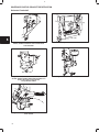
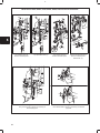
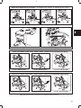
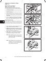
(FIGS. 1, 2)
1
Adjust Top No Load Speed,
Model Series 80000, 90000
Pneumatic Governor with Control Panel
1. Run engine until it reaches operating temperature
or for about 5 minutes.
2. Set control lever or remote controls to fast position
with engine running.
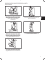
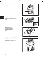
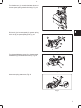
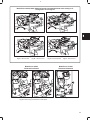
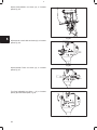
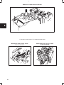
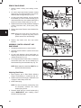
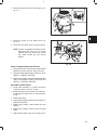
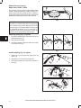
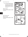
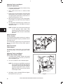
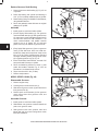
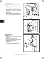
3. Adjust governed idle by turning stop nut (3) and
idle speed screw (2), Fig. 2. Turn stop nut clockwise (A) to increase speed, counterclockwise (B)
to decrease.
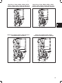
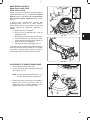
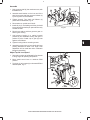
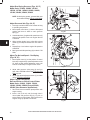
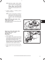
Fig. 1
2
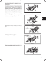
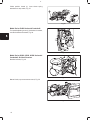
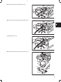
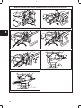
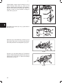
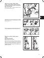
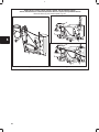
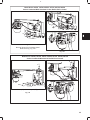
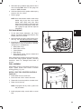
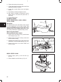
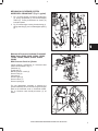
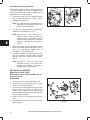
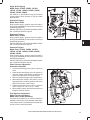
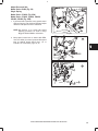
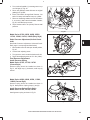
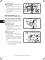
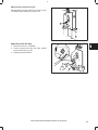
4. Use tool #19229 (4), to bend spring anchor tang (1,
Fig. 1), to obtain the proper top no load RPM,
Figs. 3 and 4. Fixed speed tang (5), Figs. 3 and 4.
Adjust Governed Idle
Some engines are equipped with governed idle.
Governed idle permits the governor to operate at idle
speeds while the engine is operating under light loads.
B
A
Fig. 2
1. Place control lever in minimum speed position with
engine running at operating condition.
4
2. 80000 Series: Hold throttle lever against stop and
adjust idle speed screw (2), to obtain 1600 RPM.
Release throttle lever. Then, turn governed idle
stop nut (3) to obtain 1750 RPM, Fig. 2.
3. 90000 Series, Low Emissions Carburetors,
Type Numbers ending in A1-A9 or E1-E9
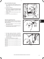
NOTE: Fixed adjustable control: before control
lever can be moved to slow position, fixed
speed tang (5), Figs. 3, 4, must be bent
down to move lever.
5
Fig. 3
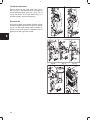
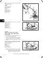
NOTE: Fixed adjustable control: After setting governed idle, move control lever back to fast
speed position and bend fast speed tang
up to hold speed control lever.
5
Fig. 4
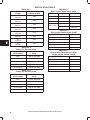
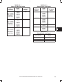
NOTE: SPECIFICATION TABLES BEGIN ON PAGE 28 OF THIS SECTION.
4
3