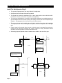
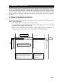
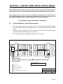
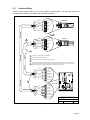
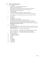
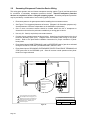
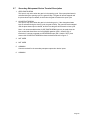
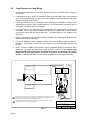
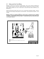
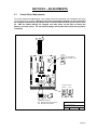
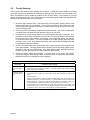
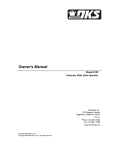
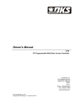
1
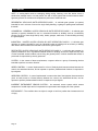
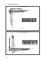
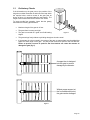
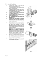
Owner’s Manual
Model 6002
Residential Vehicular Swing Gate Actuators
DoorKing, Inc.
120 Glasgow Avenue
Inglewood, California 90301
U.S.A.
Phone: 310-645-0023
Fax: 310-641-1586
www.doorking.com
P/N 6001-065 REV E, 5/04
Copyright 2003 DoorKing, Inc. All rights reserved.
Page 2
Use this manual with the following models only.
Models 6002-080 with 4302-010 circuit board.
DoorKing, Inc. reserves the right to make changes in the products described in this manual
without notice and without obligation of DoorKing, Inc. to notify any persons of any such revisions
or changes. Additionally, DoorKing, Inc. makes no representations or warranties with respect to
this manual. This manual is copyrighted, all rights reserved. No portion of this manual may be
copied, reproduced, translated, or reduced to any electronic medium without prior written consent
from DoorKing, Inc.
Page 3
IMPORTANT NOTICES
Vehicular gate systems provide convenience to their users and limit vehicular traffic onto your
property. These systems can produce high levels of force; therefore it is important that you are aware
of possible hazards associated with your gate operating system. These hazards may include pinch
points, entrapment, absence of controlled pedestrian access or traffic backup.
Be sure that the installer has instructed you on the proper operation of the gate and gate operator
system. Be sure that the installer has trained you about the basic functions of the reversing systems
associated with your gate operating system and how to test them. These include reversing loops,
inherent reversing system, and may include electric edges, photoelectric cells, or other external
devices.
•
This Owner's Manual is your property. Keep it in a safe place for future reference.
•
Loops and loop detectors, photo-cells or other equivalent devices must be installed with this
gate operator to prevent the gate from closing on vehicular traffic.
•
The speed limit for vehicular traffic through the gate area is 5 MPH. Install speed bumps and
signs to keep vehicular traffic from speeding through the gate area. Failure to adhere to
posted speed limits can result in damage to the gate, gate operator, and to the vehicle.
•
Be sure that all residents are familiar with the proper use of the gate and gate operator. Be
sure that all residents are familiar with the possible hazards associated with the gate system.
•
Be sure that all warning signs are permanently installed on both sides of the gate in an area
where they are fully visible to traffic.
•
It is your responsibility to periodically check all reversing devices. If any of these devices are
observed to function improperly, remove the operator from service immediately and contact
your installing or servicing dealer.
•
Follow the recommended maintenance schedule.
•
Do not allow children to play in the area of the operator or to play with any gate-operating
device.
•
Be sure that all activating devices are installed a minimum distance of 10 feet away from the
gate and gate operator, or in such a way that a person cannot touch the gate or gate operator
while using the activating device. If activating devices are installed in violation of these
restrictions, immediately remove the gate operator from service and contact your installing
dealer.
•
To remove the gate operator from service, operate the gate to the full open position and then
shut off power to the operator at the service panel.
SPEED BUMP
HAZARD AREA
HAZARD AREA
SPEED BUMP
Page 4
PEDESTRAINS
VEHICULAR
TRAFFIC
HAZARD
AREA
IMPORTANT SAFETY INSTRUCTIONS
WARNING - To reduce the risk of injury or death:
1. READ AND FOLLOW ALL INSTRUCTIONS.
2. Never let children operate or play with gate controls. Keep the remote control
away from children.
3. Always keep people and objects away from gate. NO ONE SHOULD CROSS
THE PATH OF THE MOVING GATE.
4. Test the operator monthly. The gate MUST reverse on contact with a rigid object
or stop or reverse when an object activates the non-contact sensors. After
adjusting the force or the limit of travel, retest the gate operator. Failure to adjust
and retest the gate operator properly can increase the risk of injury or death.
5. KEEP GATES PROPERLY MAINTAINED. Read the owner's manual. Have a
qualified service person make repairs to gate hardware.
6. The entrance is for vehicles only. Pedestrians must use separate entrance.
7. SAVE THESE INSTRUCTIONS!
Gate Construction
Vehicular gates should be constructed and installed in accordance with ASTM F2200-02; Standard
Specification for Automated Vehicular Gate Construction. For a copy of this standard, contact
ASTM directly at 610-832-9585; [email protected]; or www.astm.org.
Page 5
RESTRICTIONS AND WARNINGS
Install The Gate Operator Only If:
•
The operator is appropriate for the usage Class of the application.
•
All exposed pinch points are eliminated or guarded.
•
This operator is intended for installation only on swing gates used to control vehicular traffic.
Pedestrians must be provided with a separate access opening.
•
The gate must be installed in a location so that sufficient clearance is provided between the
gate and adjacent structures when opening and closing to reduce the risk of entrapment (see
diagram). Swinging gates should not open into public access areas.
•
The gate must be properly installed and work freely in both directions prior to the installation
of the gate operator. Do not over-tighten the operator clutch to compensate for a damaged
gate.
•
Controls must be far enough from the gate so that the user is prevented from coming in
contact with the gate while operating the controls. Outdoor or easily accessible controls
should have a security feature to prevent unauthorized use.
•
All warning signs and placards must be installed where visible in the area of the gate.
Pilaster
Fence
If greater than 4", entrapment
protection in this area is
required.
ASTM F2200 7.1.1.1
If less than 16", entrapment
protection in this area is required.
ASTM F2200 7.1.1.2
Roadway
Pedestrian Access
Gate
Fence
Gate
The operator is intended for
installation only on gates used
for vehicles. Pedestrians must
be supplied with a separate
opening.
UL 325 56.8.4.b
The gate must be installed in a location so that
enough clearance is supplied between the gate and
adjacent structures when opening and closing to
reduce the risk of entrapment. Swinging gates shall
not open into public access areas.
UL 325 56.8.4.c
Gate
Pilaster
Hinge mounted on corner
of pilaster eliminates
entrapment area.
Gate
Roadway
Roadway
If greater than 16", entrapment
protection in this area is not
required.
ASTM F2200 7.1.1.2
Page 6
Pilaster
ENTRAPMENT PROTECTION
This vehicular gate operator is equipped with an inherent adjustable current sensing system (Type A).
This system will sense an obstruction in both the opening and closing gate cycles, and will cause the
gate to reverse direction should an obstruction be encountered. If the system detects a second
obstruction before reaching the full open or close limit after the initial reversal, an alarm will activate
and the operator will require a reset before resuming normal operation. See Section 2 for more
information.
EXTERNAL ENTRAPMENT PROTECTION
Non-contact sensors must be installed to provide external entrapment protection. For gate operators
utilizing a non-contact sensor:
•
See diagram below for placement of non-contact sensors.
•
Care should be exercised to reduce the risk of nuisance tripping, such as when a vehicle trips
the sensor while the gate is still moving, and
•
One or more non-contact sensors shall be located where the risk of entrapment or
obstruction exists, such as the perimeter reachable by a moving gate or barrier.
Secondary entrapment
prevention device required.
Pilaster
Fence
Gate
Pedestrian Access
Fence
Gate
Secondary entrapment prevention device
required if space is less than 16 inches.
The gate must be installed in a location so that
enough clearance is supplied between the gate and
adjacent structures when opening and closing to
reduce the risk of entrapment. Swinging gates shall
not open into public access areas.
UL 325 56.8.4.c
The operator is intended for
installation only on gates used
for vehicles. Pedestrians must
be supplied with a separate
opening.
UL 325 56.8.4.b
Page 7
GLOSSARY
GATE – A moving barrier such as a swinging, sliding, raising, lowering, or the like, barrier, that is a
stand-alone passage barrier or is that portion of a wall or fence system that controls entrance and/or
egress by persons or vehicles and completes the perimeter of a defined area.
RESIDENTIAL VEHICULAR GATE OPERATOR-CLASS I - A vehicular gate operator (or system)
intended for use in a home of one-to four single family dwelling, or garage or parking area associated
therewith.
COMMERCIAL / GENERAL ACCESS VEHICULAR GATE OPERATOR-CLASS II - A vehicular gate
operator (or system) intended for use in a commercial location or building such as a multi-family
housing unit (five or more single family units), hotels, garages, retail store, or other building servicing
the general public.
INDUSTRIAL / LIMITED ACCESS VEHICULAR GATE OPERATOR-CLASS III - A vehicular gate
operator (or system) intended for use in an industrial location or building such as a factory or loading
dock area or other locations not intended to service the general public.
RESTRICTED ACCESS VEHICULAR GATE OPERATOR-CLASS IV - A vehicular gate operator (or
system) intended for use in a guarded industrial location or building such as an airport security area
or other restricted access locations not servicing the general public, in which unauthorized access is
prevented via supervision by security personnel.
SYSTEM - In the context of these requirements, a system refers to a group of interacting devices
intended to perform a common function.
WIRED CONTROL - A control implemented in a form of fixed physical interconnections between the
control, the associated devices, and an operator to perform predetermined functions in response to
input signals.
WIRELESS CONTROL - A control implemented in means other than fixed physical interconnections
(such as radio waves or infrared beams) between the control, the associated devices, and an
operator to perform predetermined functions in response to input signals.
INHERENT ENTRAPMENT SENSOR SYSTEM - An automatic sensor system which senses
entrapment of a solid object and is incorporated as a permanent and integral part of the operator.
ENTRAPMENT – The condition when an object is caught or held in a position that increases the risk
of injury.
Page 8
TABLE OF CONTENTS
Section 1 – Actuator Installation
1.1
Specifications ...........................................................................................................................................11
1.2
Installation Dimensions ............................................................................................................................12
1.3
Preliminary Checks...................................................................................................................................13
1.4
Actuator Installation ..................................................................................................................................14
Section 2 – Control Panel Installation and Wiring
2.1
Typical Installation / Conduit Requirements .............................................................................................17
2.2
Control Box ..............................................................................................................................................18
2.3
Actuator Wiring .........................................................................................................................................19
2.4
Main Terminal Control Wiring ...................................................................................................................20
2.5
Main Terminal Description........................................................................................................................21
2.6
Secondary Entrapment Protection Device Wiring ....................................................................................22
2.7
Secondary Entrapment Device Terminal Description...............................................................................23
2.8
Loop Detector and Loop Wiring................................................................................................................24
2.9
Battery and Solar Panel Wiring ................................................................................................................25
Section 3 – Adjustments
3.1
Circuit Board Adjustments ........................................................................................................................27
3.2
Switch Settings .........................................................................................................................................28
3.3
Switch Descriptions and Functions ..........................................................................................................29
3.4
Limit Switch Adjustment ...........................................................................................................................30
3.5
Reverse Sensitivity Adjustment ................................................................................................................31
Section 4 – Operating Instructions
4.1
Soft Shutdown ..........................................................................................................................................33
4.2
Hard Shutdown.........................................................................................................................................34
4.3
Manual Release .......................................................................................................................................35
Section 5 – Maintenance and Troubleshooting
5.1
Maintenance Schedule .............................................................................................................................37
5.2
Trouble Shooting ......................................................................................................................................38
5.3
Accessories ..............................................................................................................................................40
Page 9
Page 10
SECTION 1 – ACTUATOR INSTALLATION
Prior to beginning the installation of the swing gate actuator, we suggest that you become familiar
with the instructions, illustrations, and wiring guide-lines in this manual. This will help insure that your
installation is performed in an efficient and professional manner.
The proper installation of the vehicular swing gate actuator is an extremely important and integral part
of the overall access control system. Check all local building ordinances and building codes prior to
installing this operator. Be sure your installation is in compliance with local codes.
1.1
Technical Specifications
Class of Operation:
Type of Gate:
Motor RPM:
Max Thrust:
Voltage / Phase:
Current:
Max Gate Length:
Useful Rod Stroke
Cycles / Hr:
Speed:
Entrapment Protection:
Class I Residential Swing Gate Actuator
Vehicular Swing Gates Only
1400
300daN
115 VAC Single Phase Input Power
24 VDC Operating Power
3 amps
14 Ft.
14 inches
10/Hr
90° in approximately 20 seconds
Primary - Inherent adjustable current sensor (Type A)
Secondary - Provision for connection of non-contact (Type
B1) sensors.
1
2
3
3
5
4
8
4
7
6
1.
2.
3.
4.
Actuator Cover
Rear Mounting Bracket
Clevis Pin
Retaining Pin
5.
6.
7.
8.
Front Mounting Bracket
Manual Release Cover
Manual Release Allen
Actuator
Figure 1
Page 11
1.2
Installation Dimensions
OPEN TO THE INSIDE
L
B
Gate
Closed
X
A
Y
90°
For Gates up to 14 Feet
A
B
7
7
X1
Y1
90° / Sec
Rod Stroke
46.75 2.6
2.6
20
14
L
Gate
Opened
Note 1: MINIMUM Dimensions.
Gate Open
Figure 2
OPEN TO THE OUTSIDE
X
For Gates up to 14 Feet
A
B
L
X1
90° / Sec
Rod Stroke
7
7
46.75
2.6
20
14
Note 1: MINIMUM Dimensions.
L
90°
Gate Closed
B
A
Figure 3
Page 12
1.3
Preliminary Checks
If the dimensions on the gate post or the position of the
hinge do not allow Dimension A and/or B to be kept within
the required value, make a recess in the gate post as
shown in figure 4 to accommodate the rear bracket. The
height of the recess should be a minimum of 8 inches.
To insure trouble free operation, insure that the gate(s)
falls within the following specifications.
•
Maximum length of the gate is 14 feet..
•
The gate frame is strong and rigid.
•
The gate is mounted on a good set of ball bearing
hinges.
•
The gate swings freely without any binding throughout its entire travel.
•
If the actuator is to be mounted in the center of the gate, a support plate must be added that
spans the entire length of the gate. This will provide a secure fix point for the front bracket.
Failure to provide a secure fix point for the front bracket can cause the actuator to
damage the gate (fig. 5).
Figure 4
A support bar is designed
into this gate to prevent
damage by the actuator.
Without proper support at
the front attachment point,
the gate can be damaged.
Figure 5
Page 13
1.4
Actuator Installation
1.
2.
3.
4.
5.
6.
7.
8.
Install the rear bracket to the gate post
according to the dimensions in 1.2.
In the case of an iron post, weld the bracket
directly onto the gate post.
In the case of a brick / concrete column, flushmount a steel wall plate (not supplied) and
then weld the bracket to the plate.
Install the actuator onto the rear bracket with
the hardware supplied (fig. 6).
Fit the front bracket onto the actuator before
welding it to the gate (fig 7).
Use the manual release and release the
operator (See 4.3).
Close the gate and keeping the actuator
level, extend the rod to the dimension L
shown in 1.2. Be sure to extend the rod by
pulling it straight out from the barrel (fig. 8).
Do Not Rotate the Rod.
Temporarily fix the front mounting bracket to
the gate by two short welds (fig.9). Be sure
that this point provides a secure
attachment point for the actuator (see 1.3).
Ensure that the gate opens and closes fully
without any binding.
IMPORTANT! The mounting brackets must
be installed according to the dimensions
shown in 1.2.
Failure to locate the
attachment brackets at these locations can
cause binding in the actuator resulting in
excessive wear, damage to the motor,
control board and power transformer.
When you are satisfied with the opening of the
gate, completely weld the front bracket to the
gate. Remove the actuator when doing this to
prevent damage from welding scale.
Re-attach the actuator to the mounting
brackets. Apply a small amount of grease to
the front and rear pivot points.
4.5
3
Figure 6
Figure 7
Figure 8
Figure 9
Page 14
9.
Attach the metal tag to the slot in the top
section of the motor in order to blank off the
holes present. Do not block the holes on the
bottom of the motor (fig. 10).
10.
Rotate the small electrical housing cover on
the actuator so that the DKS logo is right side
up (fig. 11).
11.
Permanently install the two supplied warning
signs in locations so that the signs are visible
by persons on both sides of the gate. Use
appropriate hardware such as wood or sheet
metal screws (not supplied) to install the
warning signs.
Figure 10
Figure 11
Page 15
Page 16
SECTION 2 – CONTROL PANEL INSTALLATION & WIRING
Before attempting to connect any wiring to the control panel, be sure that the circuit breaker in the
electrical panel is in the OFF position. Permanent wiring must be installed to the operator as required
by local electrical codes. It is recommended that a licensed electrical contractor perform this work.
Since building codes vary from city to city, we highly recommend that you check with your
local building department prior to installing any permanent wiring to be sure that all wiring to
the operator (both high and low voltage) complies with local code requirements.
THIS CONTROL BOX MUST BE PROPERLY GROUNDED!!
2.1
Typical Installation / Conduit Requirements
•
The conduit requirements shown in figure 13 are for a typical dual swing gate installation.
The conduit requirements for your application may vary from this depending on your specific
needs.
•
Use only sweeps for conduit bends. Do not use 90° connectors as this will make wire pulls
very difficult and can cause damage to wire insulation.
•
Be sure that all conduits are installed in accordance with local codes.
1
2
4
5
3
1
Control Panel.
2
Junction box (not supplied).
3
Lead-in wire(s) from loop(s).
4
115 VAC Input power.
5
Not shown in drawing:
1. Secondary entrapment prevention device(s).
2. Optional solar panel charging system.
DOORKING, INC., INGLEWOOD, CA 90301
Title:
Master / slave interface cable (not supplied).
Date:
Model 6002 Actuator Typical Installation.
5/04
Dwg. No.
M6001-065-1
Rev.
B
Figure 12
Page 17
2.2
Control Box
•
Install the control box close to the gate so that the MASTER actuator cable can be easily
routed into the control box.
•
Be sure that conduits are installed in accordance with local electrical codes.
.5
11.0
4.0
16.25
.5
.875 KO on hinge
side of cabinet
Transformer
Housing
1.25
1.25
3.0
2.0
5.0
7.0
12.25
1.125 KO
1-Place
.875 KO
4-Places
1.5
.75
2.0
4.0
6.0
8.0
10.75
DOORKING, INC., INGLEWOOD, CA 90301
12.0
Title:
Date:
Figure 13
Page 18
Model 6002/6400 Control Mounting Dimensions
5/04
Dwg. No.
M6001-065-2
Rev.
B
2.3
Actuator Wiring
Connect each actuator cable to the control panel as shown below.
connections are made in accordance with local electrical codes.
Grn/Wht
Green
Slow Dwn
Limit
Red
Orange
MASTER
Common
Yellow
Be sure that wiring and
Slow Dwn
Limit
Blue
Motor
Brown
Motor
MASTER
3
Grn/Wht
2
Slow Dwn
Yellow
Limit
Red
Orange
SLAVE
Common
Green
Slow Dwn
Limit
Blue
Motor
Brown
Motor
1
SLAVE
MASTER
1
Junction box for slave actuator (not supplied).
2
Slave interface cable (not supplied).
3
Actuators are pre-wired. Terminals shown for reference.
4
Earlier versions of the actuators had numbered wires rather than colored wires. The number to the right of
the wire color indicates the older wiring scheme and is shown here for reference only. There was also a
white wire (not shown) in the earlier units that was not used and not connected.
SLAVE
Brown (1)
1. Motor
Blue (2)
2. Motor
Orange (3)
Red (4)
3. Limit
4. Slow Dwn
5. Limit
Green (6)
6. Slow Dwn
Grn/Wht (Yel)
7. Common
SLAVE
Yellow (5)
Brown (1)
1. Motor
Blue (2)
2. Motor
Orange (3)
Red (4)
3. Limit
4. Slow Dwn
Yellow (5)
5. Limit
Green (6)
6. Slow Dwn
Grn/Wht (Yel)
MASTER
MASTER
8. Common
4
7. Common
8. Common
DOORKING, INC., INGLEWOOD, CA 90301
Title:
Date:
Actuator Wiring
12/03
Dwg. No.
M6001-065-3
Rev.
C
Figure 14
Page 19
2.4
Main Terminal Control Wiring
Controls must be far enough from the gate so that the user is prevented from coming in
contact with the gate while operating the controls. Outdoor or easily accessible controls
should have a security feature to prevent unauthorized use.
•
Connect optional control devices to the main terminal strip as shown (fig. 16). Be sure that all
electrical connections are made in accordance with local electrical codes. Use 18 AWG wire
for all low voltage wiring, maximum distance 3000 feet. Use a low voltage surge suppresser,
DoorKing P/N 1878-010 if low voltage wire runs exceed 1000 feet. All inputs to the terminal
strip must be NORMALLY OPEN.
•
Reversing input (Terminal 8) only functions while the gate is in the closing cycle and should
not be used as an input for a secondary entrapment protection device for the open gate
cycle. See section 2.2.2 for secondary entrapment protection device wiring.
•
Do not power any devices from the circuit board other than a low voltage radio receiver.
•
If magnetic lock is used, be sure it is set for 24 Volt operation.
1
24V COMMON
RADIO RELAY / OPEN INPUT
24V RADIO PWR
OPEN INPUT / EXIT LOOP LOGIC OUTPUT
24V COMMON
1
2
3
4
5
1
Function dependant on SW1, switch 3
2
Function dependant on SW1, switch 5
3
Function dependant on SW2, switch 1, 2
4
Maglock must be set for 24 V operation
2
24 VAC INPUT
24 VAC INPUT
24V COMMON
NOT USED
NOT USED
RELAY
RELAY
ALARM RESET
9 10 11 12 13 14 15 16 17 18 19 20
NOT USED
24V COMMON
8
24 VDC MAGLOCK OUTPUT
REVERSE / SHADOW INPUT
7
24 VDC MAGLOCK OUTPUT
NOT USED
24V COMMON
6
3
RED
RED
Radio Pwr
Relay
24V Com
WHITE
BLACK
3-Wire
Receiver
4
Fire
Dept
Transformer enclosure located in
control box. Wire nut 115 VAC
input power to Black and White
transformer wires.
DKGL-S12-1(L)
Emergency
Access
Key
Switch
Card
Reader
Digital
Keypad
Telephone
Entry
GREEN
WHITE
BLACK
Note:
1. All inputs are N.O. (Normally Open)
2. Terminals 1, 5, 7, 9 and 18 are Common
DOORKING, INC., INGLEWOOD, CA 90301
Title:
Date:
Figure 15
Page 20
115 VAC
Input Power
Main Terminal Control Wiring
5/04
Dwg. No.
M6001-065-4
Rev.
B
2.5
Main Terminal Description
1.
2.
3.
4.
5.
6.
7.
8.
9.
10.
11.
12.
13.
14.
15.
16.
17.
18.
19.
20.
24V COMMON
RADIO RELAY - SINGLE BUTTTON ACTIVATION INPUT
When gate is closed, input will open gate.
When gate is open and auto close timer is turned on, input will re-set and hold timer.
When gate is open and auto close timer is turned off, input will close gate.
When gate is closing, input will reverse gate.
24V RADIO POWER
SINGLE BUTTON ACTIVATION INPUT / EXIT LOOP LOGIC OUTPUT
If SW 1,switch 3 is ON, this input is identical to Single Button Activation Input (terminal 2).
If SW 1, switch 3 is OFF, this terminal becomes the logic output of the EXIT loop detector.
24V COMMON
Not used
24V COMMON
REVERSE INPUT / SHADOW INPUT
When gate is closed, this input has no affect on the gate operator.
When gate is open and auto close timer is turned ON, input will re-set and hold timer.
When gate is open and auto close timer is turned OFF, input will prevent gate from closing.
When gate is closing, input will reverse gate if SW 1, switch 5 is OFF. If switch 5 is ON
(shadow operation), the gate will not reverse.
24V COMMON
DRY RELAY CONTACT
Operation of relay is dependent on setting of SW 2, switches 1 and 2. Relay contacts can be
set for Normally Open (NO) or Normally Closed (NC) operation. Contact rating is 1 amp
maximum at 24 Volts.
Switch 1 OFF, Switch 2 OFF: Relay activates when gate is OPEN.
Switch 1 OFF, Switch 2 ON:
Relay activates when gate is OPEN, OPENING or CLOSING.
Switch 1 ON, Switch 2 OFF:
Relay activates when gate is OPEN or OPENING.
Switch 1 ON, Switch 2 ON:
Relay activates when gate is OPENING or CLOSING.
DRY RELAY CONTACT
24 VDC MAGLOCK OUTPUT
24 VDC MAGLOCK OUTPUT
Not Used
Not Used
Not Used
ALARM RESET
24V COMMON
24 VAC INPUT
24 VAC INPUT
Page 21
2.6
Secondary Entrapment Protection Device Wiring
This swing gate operator uses an inherent entrapment sensing system (Type A) and has provisions
for connection of secondary entrapment protection devices. External entrapment protection
devices are required to insure a safe gate operating system. Secondary entrapment protection
may be provided by a combination of non-contact (Type B1) sensors.
•
Disconnect power to the gate operator before installing the non-contact sensors.
•
See Figure 17 for suggested placement of sensors. (Diagram is for illustration purposes only.
Actual placement of sensors is dependent on the installation requirements).
•
One or more non-contact sensors should be located where the risk of entrapment or
obstruction exist such as the perimeter reachable by a moving gate or barrier.
•
Use only U.L. listed (or equivalent) non-contact sensors.
•
Connect the non-contact sensors as shown below. Inputs from the photo-beam to the circuit
board are Normally Open (N.O.). Diagram does not illustrate power wiring to the photobeams. Refer to the photo-beam installation instructions for proper connection of photobeam power.
•
Photo-beam input to MAIN TERMINALS 8 and 9 will REVERSE travel of gate when activated
during the CLOSE CYCLE ONLY provided that SW1, switch 5 is OFF.
•
Photo-beam input to SECONDARY ENTRAPMENT PROTECTION DEVICE TERMIANLS will
STOP gate travel in the OPENING cycle. Gate will resume normal operation when photobeam is no longer activated.
2
Gate
3
Fence
Gate
1
1 Open Cycle Photocell
2 Close Cycle Photocell
3
3 Not Used
4 Not Used
5 Common
8
6 Common
1
Open protect beam protects area between
gate and adjacent fence during open cycle.
2
Standard reverse beam prevents gate from
hitting obstructions during the close cycle.
3
DOORKING, INC., INGLEWOOD, CA 90301
Title:
Photo-beam power. Separate power
transformer required.
Date:
Figure 16
Page 22
9
Secondary Entrapment Protection Terminal Wiring
7/03
Dwg. No.
M6001-065-5
Rev.
A
2.7
Secondary Entrapment Device Terminal Description
1. OPEN PHOTO-BEAM
This input is only active when the gate is in the opening cycle. If the open photo-beam is
activated during the opening cycle, the gate will stop. The gate will remain stopped until
the photo-beam input is cleared, at which time the gate will resume the open cycle.
2. CLOSE PHOTO-BEAM
This input is only active when the gate is in the closing cycle. If the close photo-beam
input is activated during the closing cycle, the gate will stop. The gate will remain stopped
until the photo-beam input is cleared, at which time the gate will resume the close cycle.
Note: It is recommended that the CLOSE PHOTO-BEAM input only be used when the
input to terminals 8 and 9 are set for SHADOW operation (SW 1, switch 5 ON). If
terminals 8, 9 are set to operate as a REVERSING input (SW 1, switch 5 OFF), then
connect the CLOSE PHOTO-BEAM to these terminals as shown in figure 17.
3. NOT USED
4. NOT USED
5. COMMON
Common terminal for the secondary entrapment protection device inputs.
6. COMMON
Page 23
2.8
Loop Detector and Loop Wiring
•
Loops and loop detectors are required to provide protection to vehicular traffic through the
gate system.
•
Loop detector wiring is shown for DoorKing model 9405 and 9406 Plug-In loop detectors
only. If other loop detectors are used, refer to the installation instructions supplied with those
detectors for wiring requirements.
•
If other loop detectors are used, all inputs to the terminal strip are NORMALLY OPEN. Use a
separate power supply to power external detectors. Be sure that power is turned off prior to
making any connections to the terminal strip.
•
Loop layout shown is for a typical swing gate application with two-way traffic or one-way exit
only traffic. For one-way entry only traffic, the open loop is replaced with a second reverse
loop wired in series with the first reverse loop. The 9506 detector is not needed in this
application.
•
Refer to the separate Loop Information Manual (available from DoorKing) for instructions on
installing loops or preformed loops.
•
For correct SHADOW LOOP operation, jumper wire must be placed from terminal 9 to
terminal 10. SW1 switch 5 must be OFF, SW2 switch 1 must be ON and SW2 switch 2 must
be OFF.
•
NOTE: Output of Shadow Loop Detector may be connected directly to terminals 8 and 9
(dotted line - no jumper required between 9 and 10) if SW 1, switch 5 is ON. However, with
this switch ON, terminal 8 becomes a shadow input (active only when the gate is FULL
OPEN) and all reversing devices connected to terminal 8 will operate as shadow
devices. If this is not desirable, wire the shadow loop detector as instructed in the above.
C
NC
NO
TB 1
TB 2
TB 1
REVERSE LOOP
Loop Detector
P/N 9405-010
Exit
Reverse
Loop Detector
P/N 9406-010
SHADOW LOOP
2
EXIT LOOP
8
1
2
9 10 11
Solid line shows connection with terminal 8 setup as a standard reverse input (SW1, Sw 5 OFF). If
terminal 8 is setup as a shadow reverse input (SW1, Sw 5 ON), output of loop detector can be
connected directly to terminals 8, 9 and no jumper between 9, 10.
1
Shadow loop will only hold the gate in the open position when a vehicle is present. Shadow
loop WILL NOT reverse the gate during the close cycle.
DOORKING, INC., INGLEWOOD, CA 90301
Title:
Date:
Figure 17
Page 24
Loop and Loop Detector Wiring
7/03
Dwg. No.
M6001-065-6
Rev.
A
2.9
Battery and Solar Panel Wiring
Batteries are required for the actuators to operate properly. Two 12-Volt 3.4 amp hour batteries are
provided with the actuator control panel. Batteries should be replaced every two years on average.
When replacing batteries, be sure to connect them in series with each other: POSITIVE (+) to
NEGATIVE (-).
Optional solar panels provide power from the sun to help keep the batteries charged. Observe
polarity when connecting the solar panels to the circuit board. Two solar panels are required – wired
in series.
Batteries should be connected AFTER the circuit board is powered from the supplied
transformer. Connecting the batteries first will cause a small spark and a “snap” sound. This
is normal and will not harm the circuit board. To avoid this, power the circuit first before
connecting the batteries.
2
Red
Black
Red
Black
2
1
SOLAR PANELS 10W
1
Observe Polarity!
2
Batteries and Solar Panels are wired in SERIES to provide a 24 VDC input.
DOORKING, INC., INGLEWOOD, CA 90301
Title:
Date:
Battery and Solar Panel Connections
7/03
Dwg. No.
M6001-065-7
Rev.
A
Figure 18
Page 25
Page 26
SECTION 3 – ADJUSTMENTS
3.1
Control Board Adjustments
The switch settings and adjustments in this chapter should be made after your installation and wiring
to the operator(s) is complete. Whenever any of the programming switches on the circuit board
are changed, batteries and solar panels must be disconnected and main power must be shutoff. After the switch settings are changed, turn main power on and then re-connect the
batteries and solar panels. The new switch settings will not take effect unless this procedure
is followed.
ON
SW1
1
2
3
4
5
6
7
8
SW2
1
2
3
4
TIMER
0 - 23 Seconds
SW1, Switch 4 ON
MIN MAX
NC
NO
REVERSE SENSOR
Relay Contact Setting
NO - Relay Normally Open (factory)
NC - Relay Normally Closed
MASTER
SLAVE
MIN MAX
MIN MAX
DOORKING, INC., INGLEWOOD, CA 90301
Title:
Date:
Control Board Adjustments
7/03
Dwg. No.
M6001-065-8
Rev.
A
Figure 19
Page 27
3.2
Switch Settings
The two DIP-switches located on the circuit board are used to program the actuators to operate in
various modes and to turn on or off various operating features. Whenever a switch setting is
changed, batteries and solar panels must be disconnected and power must be turned OFF.
After the switch settings are changed, turn power back on and then re-connect the batteries
and solar panels for the new setting to take affect. Check and review ALL switch settings prior to
applying power to the control panel.
SW 1 (TOP SWITCH)
SWITCH
FUNCTION
SETTING
DESCRIPTION
1
Direction
Master
Set this switch so that the MASTER actuator runs OPEN after
initial power up and activation.
2
Direction
Slave
Set this switch so that the SLAVE actuator runs OPEN after initial
power up and activation.
3
Exit Loop
Logic Output
4
Auto-Close
Timer
5
OFF
ON (normal)
Output of loop detector in EXIT port is switched to terminal 4.
Output of loop detector in EXIT port feeds directly to processor.
OFF
ON
Auto-close timer is OFF. Manual input required to close gate.
Auto-close timer is ON. Adjustable from 1-23 seconds.
Reverse
Shadow
OFF (normal)
ON
Terminal 8 is STANDARD reverse input.
Terminal 8 is SHADOW reverse input.
6
Overlap
OFF
ON
Master and slave actuators start at same time.
Master actuator starts 1-2 seconds prior to slave actuator.
7
Single
Dual
OFF
ON
Switch is OFF for a single actuator.
Switch is ON for two actuators (master / slave).
8
Not Used
OFF
Leave in OFF position.
SW 2 (BOTTOM SWITCH)
SWITCH
FUNCTION
1 and 2
Relay
Operation
1-OFF
1-OFF
1-ON
1-ON
3
Not Used
OFF
Leave in OFF position.
4
Not Used
OFF
Leave in OFF position.
Page 28
SETTING
2-OFF
2-ON
2-OFF
2-ON
DESCRIPTION
Relay activated only when gate is FULL OPEN.
Relay activated whenever gate is NOT CLOSED.
Relay activated when gate is OPENING and OPEN.
Relay activated when gate is OPENING and CLOSING.
3.3
Switch Descriptions and Functions
SW1 Switch 1: Sets direction of the master actuator so that it cycles open upon initial power up and
open command. If the actuator begins to cycle close upon initial power up and open command, turn
power off and change the setting on this switch.
SW1 Switch 2: Sets direction of the slave actuator so that it cycles open upon initial power up and
open command. If the actuator begins to cycle close upon initial power up and open command, turn
power off and change the setting on this switch.
SW1 Switch 3: Determines if the output of the loop detector (DoorKing loop detectors only) plugged
into the EXIT port will be sent directly to the microprocessor to open the gate, or if the output is
directed to terminal 4 where it can then be connected to other input terminals.
SW1 Switch 4: Turns the auto close timer on or off. Maximum time that the close timer can be set for
is 23 seconds.
SW1 Switch 5: Sets the input to terminal 8 to act as a standard reverse input (OFF) or to act as a
shadow input (ON). If shadow setting is used, input to terminal 8 will only hold the gate in the full
open position. Once the gate begins to close, the input will not reverse the gate.
SW1 Switch 6: Turns the overlap feature on or off. When turned ON, the master actuator begins its
cycle 1-2 seconds prior to the slave actuator, allowing the master gate to reach its full closed position
1-2 seconds before the slave gate. This feature is useful when a magnetic lock is used to secure the
gates.
SW1 Switch 7: Sets up the circuit board for single or dual (master / slave) gate operation.
SW1 Switch 8: Spare switch. Leave in the OFF position.
SW2 Switches 1 and 2: These work in conjunction with each other and determine when the relay on
the board will be activated. This relay can be used as a switch for various functions such as
illuminating a warning light when the gate is moving, or turning on a green light when the gate is full
open. This relay is not available for these uses if it is being used for the shadow loop function.
Switches 3-4: Spare switches. Leave these in the OFF position.
Page 29
3.4
Limit Switch Adjustment
The limit switches on this actuator are adjustable to allow you to control the travel of the gate and to
precisely set the full open and full closed position of the gate. This feature is especially useful in
applications where the gate opens only partially, such as on a curved driveway. Figure 20 shows the
maximum amount of adjustment for each of the limit assemblies.
1. To adjust the limit switches, the actuator must be installed on the gate and power to the
circuit board must be ON.
2. Use the release key and place the actuator in manual operation (See 4.3).
3. Manually move the gate to the desired open position.
4. Loosen the small screw on the limit assembly being adjusted and slowly slide the
assembly until the LIMIT LED on the circuit board illuminates.
5. Tighten the screw to lock the limit assembly in place.
6. Repeat these steps for the slave operator.
7. Manually move the gate to the desired close position.
8. Loosen the small screw on the limit assembly being adjusted and slowly slide the
assembly until the LIMIT LED on the circuit board illuminates.
9. Tighten the screw to lock the limit assembly in place.
10. Repeat these steps for the slave actuator.
11. Use the release key to relock the actuator into normal operation.
12 Test the travel of the actuators by activating an open device.
4.75
2.25
Figure 20
Page 30
2
3.5
Reverse Sensitivity Adjustment
This vehicular gate operator is equipped with an inherent adjustable reverse sensor (Type A) that is
used as the primary entrapment sensing system. Upon sensing an obstruction in either the opening
or closing gate cycle, the gate operator will reverse direction. For this system to function correctly,
the gate must be properly installed and work freely in both directions. A good set of roller bearing
hinges is essential for proper swing gate operation.
Both the master and slave actuator each has its own reverse sensitivity adjustment. These
are independent of each other and must be adjusted individually.
1. Activate the gate operator by momentarily shorting terminal 1 and 2 with a 1-foot piece of
18 AWG wire.
2. While the gate is running open, slowly rotate the MASTER reverse sensitivity
potentiometer clockwise until the gate reverses travel, then rotate the potentiometer 1/8
turn counter clockwise. Note: Rotating the sensitivity adjustment clockwise INCREASES
the reverse sensitivity. Rotating this adjustment counter-clockwise DECREASES the
reverse sensitivity. NOTE: After the gate has reversed, the operator will assume a "soft
shutdown" making it necessary to initiate the cycle again by momentarily shorting across
terminals 1 and 2 as in step 1.
3. Operate the gate a few times to be sure that it cycles completely.
4. Place an immobile object along the path of the gate so that the gate will strike it while in
the open or close cycle. The gate must reverse direction after striking the object. If it does
not, increase the reverse sensitivity by turning the potentiometer 1/8 turn clockwise, then
repeat this test. NOTE: After the gate has reversed, the operator will assume a "soft
shutdown" making it necessary to initiate the cycle again by momentarily shorting across
terminals 1 and 2 as in step 1.
5. You may have to repeat step 4 several times to find the correct sensitivity adjustment.
6. If a master / slave system is in use, repeat steps 1 through 5 for the slave actuator using
the SLAVE reverse sensitivity potentiometer.
Page 31
Page 32
SECTION 4 – OPERATING INSTRUCTIONS
Under various entrapment conditions the operator will assume either a soft or hard shutdown (alarm)
condition. To determine what type of reset action is required, you will need to understand how the
different entrapment conditions affect the gate operator.
4.1
Soft Shutdown
This occurs in various situations where the inherent or secondary entrapment protection devices have
been activated. In a soft shutdown condition, the operator will not respond to any input that was
present when the entrapment protection device sensed an obstruction. If the gate stops at the open
position, the operator will not respond to the automatic close timer.
•
Example 1: A time clock keys the gate open in the morning and an entrapment protection
device senses an obstruction prior to the gate reaching the full open position. If the
entrapment is sensed by the inherent system, the gate will reverse and run back to the closed
position. The time clock input is still present, but the gate will not re-open.
NOTE: In some systems, the time clock input comes from the telephone entry system relay. This
same relay may also provide open commands for a card reader, MicroPLUS transmitters and the
visitor telephone entry. If so, these devices will also be disabled in a soft shutdown condition.
•
Example 2: If the gate is closing and an entrapment protection device is activated, the gate
will either stop or reverse and run back to the open position, depending upon if the secondary
or inherent device was activated. The automatic close timer will not close the gate.
•
Example 3: Vehicle arrives at open loop and gate runs towards the open position. The
inherent entrapment protection is activated. The gate reverses and runs back to the closed
position. If the vehicle is still present at the open loop a soft shutdown condition does not
occur. The loop input provides an immediate reset of the operator and the gate will again run
to the open position.
In some conditions, a soft shutdown will reset as soon as the entrapment condition clears. For
example, if a non-contact sensor (photo cell) is sensing an obstruction, the operator will stop the gate
and assume a soft shutdown condition. When the photocell clears, the operator will return to normal
operation.
When the operator is in a soft shutdown, activation of any "intended input" will reset the operator. An
"intended input" includes any command, any standard safety input and any loop input. Activating any
of these inputs will reset the gate. At that point the gate will return to normal operation. If the gate is
open, the automatic close timer will then time out and close the gate.
Page 33
4.2
Hard Shutdown
A hard shutdown condition occurs when the inherent entrapment protection system has sensed two
consecutive obstructions before the gate reaches the full open or closed position.
•
Example: The gate is closing and the inherent entrapment protection system senses an
obstruction and causes the gate to reverse direction. As the gate begins to run in the open
direction, a second obstruction is sensed prior to the gate reaching the full open position.
Once the second obstruction has been sensed, the operator will stop, the audio alarm will be
activated and all standard inputs are shut down (including open commands, safety
commands, loop inputs, etc.).
•
NOTE: The audio alarm will remain activated for a maximum of five minutes, or until the
operator receives a reset input. The hard shutdown condition will remain in affect even if the
audio alarm shuts off after five minutes.
•
After 5 minutes, the audio alarm will “chirp” every 5 seconds. This indicates that the operator
is in a hard shutdown condition and the reset switch must be activated to reset the operator
and silence the alarm.
When the operator is in a hard shutdown condition (audio alarm activated or audio alarm “chirps”
every 5 seconds), the only way to reset the gate operator and return it to normal operation is to
activate the reset input (terminals 17 and 18). An alarm-reset switch can be mounted external of
the gate operator provided that it is installed in the line of sight of the gate and gate operator.
•
Before resetting a hard shutdown, determine why the shutdown occurred. Inspect the gate
for any obstructions along its path that could have activated the inherent entrapment sensing
system. Inspect the gate and gate hardware.
•
NOTE: Models 6001 and 6002 operators have a built-in reset push button located on the
bottom of the control box. Activating this button will return the gate operator to normal
operation, but will not activate the gate operator.
ALARM
Once the gate has been reset, an open or close command is needed to start the gate operator. Most
activating commands will cause the gate operator to cycle to the open position. This includes
activation of a key switch or open command and activation of an open loop. Activation of a close
command will run the gate to the closed position.
Push to Reset
Page 34
4.3
Manual Release
The gate can be operated manually in the event of a power failure or malfunction by removing the
cover and inserting the release key.
NOTE: Never attempt to manually operate any gate with an operator attached to it until you
have verified that power to the operator has been shut-off.
To Release the Actuator - Refer to Figure 21.
1.
2.
3.
4.
5.
Open the key cover.
Insert the key.
Unlock the cover.
Open the cover and remove the allen wrench.
Insert the allen wrench into the release
mechanism and rotate it 90°.
6. The actuator is now in manual operation.
•
Figure 21
Returning to Normal Operation – Figure 22.
1. Insert the allen wrench into the release
mechanism and rotate it 90°.
2. Place the allen wrench back into the cover and reinstall the cover onto the actuator.
3. Lock the cover.
4. Remove the key.
5. Close the key cover.
6. The actuator is now in normal operation.
Figure 22
Page 35
Page 36
SECTION 5 – MAINTENANCE AND TROUBLESHOOTING
Inspection and service of this gate operator by a qualified technician should be performed anytime a
malfunction is observed or suspected. High cycle usage may require more frequent service checks.
5.1
Maintenance Schedule
When servicing the gate operator, always check any secondary (external) reversing devices (loops,
photo eyes, etc.) for proper operation. If external reversing devices cannot be made operable, do not
place this operator in service until the malfunction can be identified and corrected.
Always check the inherent reversing system when performing any maintenance. If the
inherent reversing system cannot be made operable, remove this operator from service until
the cause of the malfunction is identified and corrected. Keeping this operator in service
when the inherent reversing system is malfunctioning creates a hazard for persons which can
result in serious injury or death should they become entrapped in the gate.
When servicing this gate operator, be sure that the 24 VAC input power, batteries and solar panels
are disconnected.
MONTHLY
INTERVAL
MAINTENANCE SCHEDULE
3
Alarm
Activate the primary (inherent) reverse system by blocking the gate
with a solid object. When the gate reverses, block the gate in the
opposite direction prior to the limit being reached. The entrapment
alarm should activate. Press the reset button to silence the alarm.
Batteries
Check the batteries for any leakage or loose connections. Batteries
should be replaced every two years.
Fire Dept.
Check emergency vehicle access device for proper operation.
Gate
Inspect for damage. Check gate hinges for wear and grease if
necessary.
Primary Reverse
System
Loop(s)
Check vehicular reverse and shadow loops for proper operation.
Check manual release for proper operation.
Solar Panels
Complete
12
Check that the gate reverses on contact with an object in both the
opening and closing cycles. Adjust the clutch if necessary.
Release
Secondary
Reverse Device
6
Check secondary (external) reverse device(s) stop or reverse the
gate when activated.
Wipe off the panels with a clean dry cloth. Dirty solar panels will not
properly charge the batteries.
Complete check of gate and gate operating system.
Page 37
5.2
Trouble Shooting
Have a good VOM meter to check voltages and continuity. A Meg-Ohm meter capable of checking
up to 500 meg-ohms of resistance is necessary to properly check the integrity of the ground loops.
When a malfunction occurs, isolate the problem to one of three areas: 1) the operator, 2) the loop
system, 3) the keying devices. One of the first steps in developing good trouble shooting habits is to
disconnect all external inputs to the circuit board.
1. Check the input indicator LEDs. They should only come ON when a keying device (card
reader, push button, etc.) is activated. If any of the input LEDs are ON continuously, this
will cause the gate operator to hold open. Disconnect the keying devices one at a time
until the LED goes OFF.
2. Check any external secondary entrapment protection devices. Any short or malfunction
in these devices can cause the gate operator to stop or to hold open.
3. A malfunction in a loop or loop detector can cause the gate operator to hold open, or to
not detect a vehicle when it is present over the loop. Pull the loop detector circuit boards
from the loop ports on the operator circuit board. If the malfunction persist, the problem
is not with the loop system. For more information on trouble shooting loops and loop
detectors, refer to your loop detector instruction sheet and to the DoorKing Loop and
Loop Detector Information Manual.
4. Check to be sure that there are no shorted or open control wires from the keying devices
to the gate operator. If a keying device fails to open the gate, momentarily jumper across
terminals 1 and 2 on the control board. If the gate operator starts, this indicates that a
problem exist with the keying device and not with the gate operator.
5. Check the supply voltage and batteries. A voltage drop on the supply line (usually
caused by using too small supply voltage wires) will cause the operator to malfunction.
Batteries should be fully charged for proper operation.
TROUBLESHOOTING
SYMPTON
Actuator(s) will not
run. Power LED is
OFF.
Actuator(s) will not
run. Power LED is
ON.
Page 38
POSSIBLE SOLUTION(S)
•
Check that power to the operator is turned ON.
•
Check for 24 VAC at terminals 19 and 20. If voltage measures OK, check the terminal
strip or replace the circuit board.
•
Momentarily jumper terminal 1 to terminal 2. If the input LED does not come ON, check
the terminal strip or replace the circuit board. If LED does come ON, proceed to next
steps.
•
Check the fuses.
•
Remove the circuit board. With two 14 AWG insulated jumper wires, momentarily jumper
the battery terminals to the motor terminals (1, 2) of the Master actuator connector. The
actuator should run. Swap the two wires at the terminal strip. The actuator should run in
the opposite direction. Repeat these steps using the Slave actuator connector.
•
If the actuator(s) run in both directions in the step above, replace the control board. If the
actuator(s) do not run, or run in only one direction, problem can be a bad actuator, wire
connections from the control board to the actuator(s) or a bad control board.
Gate opens a short
distance, then
stops and reverses.
Gate opens but will
not close.
Gate closes but will
not open.
Gate starts to
close, then
reverses to open.
Gate closes and
then re-opens.
Alarm sounds for 5
minutes and then
beeps once every 5
seconds. Operator
will not run.
•
Disconnect the gate from the actuator and check that the gate swings freely without any
binding.
•
Check the reverse sensitivity.
•
Check the secondary safety devices.
•
Replace the circuit board.
•
Check the input LEDs. Any ON will hold the gate open and indicates a problem with a
keying device.
•
Check the secondary safety devices. Any activated will hold the gate open and indicates a
problem with the safety device.
•
Check the loop detectors. Any activated can hold the gate open and indicates a problem
with the loop detector or ground loop.
•
Operator may be in a “soft shutdown.” Activate any keying device to determine if operator
returns to normal operation.
•
If automatic close is desired, be sure SW-1, switch 4 is ON.
•
Operator may be in a “soft shutdown.” Check input LEDs. If any are ON, momentarily
disconnect, then re-connect the wire going to the input terminal. Actuator should open.
•
Check to be sure that the actuator is running in the proper direction. Turn power OFF,
disconnect batteries and solar panels, and then back ON. Activate a keying device.
Actuator should run in the open direction. If actuator runs in the close direction, turn power
OFF and change direction switch SW-1, switches 1 and/or 2. Re-test and reconnect
batteries and solar panels.
•
Be sure that the respective LED on the control board lights when the keying device
connected to the respective terminal is activated. If LED does not light, momentarily place
a jumper wire from terminal 1 to the input terminal being checked. If LED lights and gate
opens, problem is with the keying device. If LED does not light, replace control board.
•
Disconnect the gate from the actuator and check that the gate operates freely without any
binding.
•
Check the loop detector LEDs and input LEDs. Any that flash ON will cause the gate to
reverse.
•
If a shadow loop is used, check for proper wiring. A mis-wired shadow loop detector will
cause the gate to reverse.
•
Replace the circuit board.
•
Check for any input or loop detector LEDs that are ON.
•
Check that the operator is running in the proper direction (see “gate closes but will not
open” above).
•
Operator is in a “hard shutdown” condition. Reset switch must be activated to return
operator to normal operation.
Page 39
5.3
Accessories
The following accessory items are available for the model 6001 and 6002 swing gate operators.
Photo Cell
Loop Detector
Magnetic Lock
Time Clock
Torsion Rods
Hinges
Surge Devices
Gate Scale
Speed Bumps
Solar Panels
Batteries
Fuse
Page 40
Non-contact (photo-cells) sensors for use as a secondary entrapment
protection device.
EMX Industries, Inc., Model IRB-325
MMTC, Inc., Model E3K-R10K4-NR
Detectors plug directly into ports on circuit board simplifying wiring.
P/N 9405-010 - Single channel detector
P/N 9406-010 – Two-channel detector
Magnetic lock provides an excellent means to secure swing gates and is
a fail-safe device allowing emergency vehicle access upon power
outage.
P/N 1216-080 or 1216-081
7 day and 365 day time clocks can be used to automatically open gate at
pre-set time and days. Compact clock fits inside the operator.
P/N 2600-791 - 7 day clock P/N 2600-795 - 365 day clock
Torsion rod assembly is used on uphill swing gates for counter balance.
P/N 1203-083
Heavy-duty ball bearing hinges provide easy swing gate operation.
P/N 1200-009 - Two required.
High and low voltage surge suppressers help prevent circuit board failure
caused by lightning strikes and power surges.
P/N 1876-010 - High Voltage, P/N 1878-010 - Low Voltage
Use to test torque required to move gate. P/N 2600-225
Prefabricated six-foot speed bump reduces traffic speed through gate
system. P/N 1610-150
10 Watt solar panels provide charge to the batteries. Two required.
P/N 2000-075
Replacement batteries, 12 Volt 3 Amp Hour. Two required.
P/N 1801-009
Replacement fuse – 5 Amp
P/N 4601-058
Page 41