1
4201-003 Rev C
Page 1 of 8
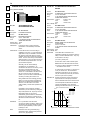
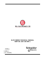
ELITE SERIES TECHNICAL MANUAL
PART NO. 4201-180 REV J
Head Office:
81 Austin Street
P.O. Box 741
Napier
New Zealand
Tel.: +64-6-843-5855
Fax.: +64-6-843-5185
Elite Series Technical Manual
PDL Part No.4201-180 Rev J
4201-003 Rev C
Page 2 of 8
Elite Series Technical Manual
PDL Part No.4201-180 Rev J
IMPORTANT NOTES
SAFETY WARNINGS:
–
It is the installer’s responsibility to ensure the configuration and installation of the Elite Series meets the
requirements of any site specific, local and national electrical regulations.
–
The Elite Series operates from HIGH VOLTAGE, HIGH ENERGY ELECTRICAL SUPPLIES. Stored charge is
present after switch off.
–
Due to the high leakage currents inherent to AC drives, earth connection of both the motor and the Elite Series is
essential before connection to the supply. The Elite Series must be permanently connected to the supply.
–
For safety reasons, normal operation of the Elite Series requires front covers/doors to be in place and secured
closed.
–
Do not attempt to isolate the motor while the Elite Series is running.
–
Some parameter settings may cause the Elite Series to start automatically after power failure.
–
Motor overspeed operation may be limited by mechanical constraints.
RELIABILITY WARNINGS:
–
Always screen control wiring.
–
Ensure that the Elite Series is not mounted in an adverse environment.
SERVICING WARNINGS:
–
Service only by qualified personnel.
–
Always isolate and allow to discharge before servicing.
–
Never replace ceramic fuses with glass types.
–
Always wear safety glasses when operating with the cover removed.
–
The Elite Series contains static sensitive printed circuit boards. Use static safe procedures when handling these
boards.
–
Never work on live equipment alone.
–
Observe all recommended practices.
NOTES:
This manual and the screen list contained within this document relate to Elite Series software version 3.7. Refer
to Screen Z2 for the software version of your Elite Series.
–
It is the responsibility of the end user/purchaser to ensure that operators understand how to use this equipment
safely. Please read this manual thoroughly.
–
The latest revision of this manual is available from our web-site www.pdl.co.nz.
4201-003 Rev C
Page 3 of 8
–
Elite Series Technical Manual
PDL Part No.4201-180 Rev J
DEDICATION TO QUALITY
AC Motor Control Products can dramatically improve your process control, productivity and energy efficiency, but only if they are
working correctly.
Which is why we at PDL Electronics go to great lengths in our design and manufacturing, to ensure that our products operate
correctly first time, every time.
An extensive research and development investment ensures that this product is one of the most technically advanced in the
world, with built-in strength and robustness to suit your application and environment.
Our AS/NZS ISO 9001 certification gives you the confidence of our international, independently certified Quality Assurance
program. All staff are actively involved in continuous improvement programs with a customer focus.
The components that go into our products are selected from the best in the world - and must pass our rigorous and demanding
test program.
Finally, every new drive design is run through a rigorous test program, including full load operation at above rated
temperature, under the most demanding load conditions.
Our dedication to quality makes the PDL Electronics product, regardless of price, less expensive than other controllers in
the long run.
COMPREHENSIVE SUPPORT PROGRAM
The PDL Electronics customer support program demonstrates our confidence in our Quality Assurance system. We have total
faith in our products and their reliability, and so provide a comprehensive warranty.
Fully trained engineers and technicians, with a wealth of experience and easy access to information, can assist in solving
any of your drive application projects.
Our service staff are available for commissioning, after sales service, and repairs, 24 hours a day, seven days a week.
We select capable and highly qualified representatives to act as our distributors and service agents. Only after passing PDL
Electronics' intensive training program are they accredited for repair or on-selling of our products.
To further support our products and customers, we run a series of comprehensive training programs focusing on self
maintenance and application advice. These are available on-site and at our Head Office.
REVISION HISTORY
4201-003 Rev C
Page 4 of 8
Date:
Revision:
April
Nov.
May
March
Dec.
1997
1997
1998
1999
2000
D
E
F
G
H
Oct.
April
2001
2002
I
J
Description:
Process Control and Fibre Optic Mode added.
Elite Software Version 2.0
Ultradrive specifications added
Add large Ultradrive specifications
Update to software revision 3.5. UL listings added.
500V ratings & Open Loop Vector added.
New 500V ratings and parallel drive fault codes added
UL Cables sizes added
Copyright 2000, PDL Electronics Ltd., Napier, New Zealand. Microdrive Elite SeriesRTM and Ultradrive Elite SeriesRTM are PDL registered trademarks
Elite Series Technical Manual
PDL Part No.4201-180 Rev J
4201-003 Rev C
Page 5 of 8
CONTENTS
1
INTRODUCTION TO THE ELITE SERIES AC MOTOR CONTROLLER
9
1.1
THE CONCEPT
9
1.2
THE ELITE SERIES RANGE
9
1.3
THE BASIC PRINCIPLE OF FLUX VECTOR CONTROL
9
1.4
CONFIGURATION OF CONTROLLER TYPE
9
1.5
CONTROL CONFIGURATION OPTIONS
9
2
ELITE SERIES SPECIFICATIONS
10
2.1
ELITE SERIES SPECIFICATIONS
10
3
DESCRIPTIONS
13
3.1
DESCRIPTION OF THE ELITE SERIES HARDWARE
3.1.1 Overview
3.1.2 Power Conversion
3.1.3 Control Board
3.1.4 The Display Unit and Controls
3.1.5 Control Inputs and Outputs
13
13
15
15
18
18
3.2
DESCRIPTION OF THE ELITE SERIES CONTROL SYSTEM
3.2.1 Structure of the Inputs and Outputs
3.2.2 Structure of the Motor Control System
20
20
21
4.1
THE MOTOR
4.1.1 Sizing the Motor and Elite Series
25
25
4
APPLICATION RECOMMENDATIONS
25
4.1.2
4.1.3
4.1.4
4.1.5
25
25
25
26
Operation Above Motor Rated Speed
Operation of More Than One Motor
Thermal Protection of the Motor
Large Frame-size Motor Considerations
4.2
THE ENCODER
4.2.1 Choice of Encoder
4.2.2 Connection of the Encoder
26
26
26
4.3
SWITCHING
4.3.1 Power Switching
4.3.2 Motor Switching
26
26
26
4.4
TORQUE AND SPEED CONTROL MODES
4.4.1 Torque Control Mode
4.4.2 Speed Control Mode
4.4.3 Switching Between Torque and Speed
Control Modes
26
26
27
4.5
DYNAMIC BRAKING
27
5
UNPACKING, INSTALLATION AND CONNECTION
28
5.1
UNPACKING
28
5.2
INSTALLATION
28
5.3
MANUFACTURER'S RECOMMENDATIONS
28
5.4
POWER WIRING CONNECTIONS
28
5.5
CONTROL WIRING CONNECTIONS
29
5.6
SHAFT ENCODER CONNECTIONS
29
5.7
FIBRE OPTIC CONNECTION
29
5.8
DYNAMIC BRAKE DETAILS
29
Elite Series Technical Manual
27
PDL Part No.4201-180 Rev J
5.9
ANCILLARY EQUIPMENT
29
5.10
COMMISSIONING DETAILS
29
6
SERVICE AND MAINTENANCE
33
6.1
FAULT FINDING
6.1.1 Electrical Failure
6.1.2 Protective Fault Operation
6.1.3 Encoder Failure
6.1.4 Incorrect Set-up or Adjustment
6.1.5 Poor Vector Control Tuning
6.1.6 Failure of External Control Device
6.1.7 Failure of the Display Unit
33
33
33
33
33
33
33
33
6.2
THE FAULT SCREEN
6.2.1 Control of the Fault Screen
6.2.2 Fault Messages
34
34
34
6.3
USE OF LED INDICATORS
37
6.4
FUSE FAILURE
38
7.1
DISPLAY UNIT CONTROLLABILITY
39
7.2
MENU STRUCTURES AND SCREENS
7.2.1 Screen Lists
7.2.2 Scrolling, Unfolding and Folding
39
39
39
7
THE ELITE SERIES DISPLAY UNIT
39
7.2.3 Parameter Conventions
7.2.4 Adjusting a Screen Value
7.2.5 Off to Modify
39
39
40
OPERATING MODES
7.3.1 Summary of Operating Modes
40
7.3.2 Swapping Between OPERATION and COMMISSIONING Modes
7.3.3 MENU SET-UP Mode
40
40
41
8.1
PDL VYSTA® FOR WINDOWS CONFIGURATION SOFTWARE
42
8.2
CUSTOM SCREEN CONFIGURATION
42
8
CUSTOMISATION OF CONTROL
42
8.3
PDL DRIVELINK FOR WINDOWS SOFTWARE PACKAGE
42
8.4
MODBUS COMMUNICATIONS CONNECTIONS BETWEEN PC AND DRIVE
8.4.1 The Elite Series to PC Connection
8.4.2 Configuring the Connection
8.4.3 Down-loading from a PC to the Elite Series
42
42
42
42
9
THE DEFAULT SCREEN LIST
43
10
APPLICATION EXAMPLE - SIMPLE FAN SPEED CONTROL
85
7.3
86
COMMISSIONING CONFIGURATION CONTROL — TERMINALS
88
ELITE SERIES SPARES LIST
89
ULTRADRIVE ELITE SPARES 400VAC (FRAMES 5-7)
91
ULTRADRIVE ELITE SPARES 500V (FRAMES 5-7)
92
4201-003 Rev C
Page 6 of 8
COMMISSIONING CONFIGURATION RECORD — SCREENS
Elite Series Technical Manual
PDL Part No.4201-180 Rev J
4201-003 Rev C
Page 7 of 8
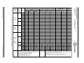
FIGURES
Figure 2.1:
Figure 2.2:
Figure 3.1:
Figure 3.2:
Figure 3.3:
Figure 3.4:
Figure 3.5a:
Figure 3.5b:
Figure 3.5c:
Figure 3.5d:
Figure 3.6:
Figure 3.7a:
Figure 3.7b:
Figure 3.8:
Figure 3.9:
Figure 3.10:
Figure 4.1:
Figure 4.2:
Figure 4.3:
Figure 5.1:
Figure 5.2:
Figure 5.3:
Figure 5.4:
Figure 5.5:
Figure 5.6:
Figure 5.7:
Figure 5.8:
Figure 7.1:
Figure 7.2:
Figure 7.3:
Figure 7.4:
Figure 7.5:
Figure 7.6:
Figure 9.1a:
Figure 9.1b:
Figure 9.1c:
Figure 9.1d:
Figure 9.2:
Figure 9.3:
Figure 9.4:
Figure 9.5:
Figure 9.6:
Figure 9.7:
Figure 9.8:
Figure 9.9:
Figure 9.10:
Figure 9.11:
Figure 9.12:
Figure 9.13:
Figure 9.14:
Figure 9.15:
Figure 9.16:
Figure 9.17:
Figure 9.18:
Figure 9.19:
Figure 9.20:
Figure 9.21:
Figure 9.22:
Figure 9.23:
Figure 9.24:
Figure 9.25:
Figure 9.26:
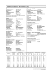
Elite Series 400V Nominal and Re-rated Specifications
Elite Series 500V Nominal and Re-rated Specifications
Microdrive Elite Series Dimensions
Ultradrive Elite Frame 4 Dimensions
Ultradrive Elite Frames 5 to 7 Dimensions
Elite Series Electrical Overview
Power Electronics - Microdrive Elite Frames 1 & 2
Power Electronics - Microdrive Elite Frame 3
Power Electronics - Ultradrive Elite Frame 4
Power Electronics - Ultradrive Elite Frames 5 to 7
The Display Unit and Keys
Control Terminals T1-T21
Control Terminals T22-T42
Structure of the Elite Series Input/Output Processing System
Structure of the Elite Series Motor Control System
Process Control
Elite Series Thermal Overload Characteristics
Typical Motor Thermal Derating
Dynamic Brake Resistor Ratings (Typical)
Elite Series Power Terminal tightening Torque
Elite Series Power Connection
Shaft Encoder Connection Details
Microdrive Elite Series Cable Configuration
Ultradrive Elite Frame 4 Cable Configuration
Ultradrive Elite Frame 5 Cable Configuration
Ultradrive Elite Frame 6 Cable Configuration
Ultradrive Elite Frame 7 Cable Configuration
The Display Unit
Screen Unfolding and Folding
Setting Commission Mode after a Password has been set
Setting a Password for the First Time
Entering and Exiting Menu Set-up Mode
Typical Screen Display in Menu Set-up Mode
Screen List A-H
Screen List I-N
Screen List O-P
Screen List R-Z
Comparator Source Selection
Local Start/Stop-Reset Control
Speed Reference Source Selection
Torque Reference Source Selection
Analogue Input Format Selection
Analogue Input Scaling and Torque/Speed Limits
Analogue Input Reference Zero Band
Input Mode Selection
Active High/Active Low Selection
Multi-function Input Functions (Selectable Functions)
Fibre Optic Control Mode Selection
Skip Speeds
Special Functions using Multi-Reference Setpoints
Multi-Reference 2 Wire Functions
Function of Multi - Reference 3 Wire
Analogue & Fibre Outputs Source Selection
Analogue Output Format Selection
Analogue Output Scaling
Relay Table Selection
Process Control Setpoint Source
Process Control Feedback Source
Dual Acceleration/Deceleration Rates
Stopping Modes
Start and Off Delay Times
Initialisation Levels
Elite Series Technical Manual
11
12
13
14
15
16
17
17
17
17
18
19
20
22
23
24
25
25
27
29
29
30
30
31
31
32
32
39
39
40
40
41
41
43
44
45
46
49
53
54
54
55
55
56
57
58
59
59
61
62
62
63
65
66
66
67
68
69
70
73
73
80
PDL Part No.4201-180 Rev J
SYMBOLS USED
Caution, risk of electric shock
ISO 3864, No. B.3.6
Caution (refer to accompanying documents)
3
Three-phase alternating current
ISO 3864, No. B.3.1
IEC 617-2, No. 02-02-06
________
__ __ __
Direct Current IEC 417, No. 5031
Protective Earth (PE) Terminal
IEC 417 No. 5019
Earth (ground) Terminal IEC 417 No. 5017
M
Induction motor, three phase, squirrel cage
IEC 617-2, No. 06-08-01
4201-003 Rev C
Page 8 of 8
3
Elite Series Technical Manual
PDL Part No.4201-180 Rev J
9
1
1.1
INTRODUCTION TO THE ELITE SERIES AC MOTOR CONTROLLER
THE CONCEPT
The AC induction motor is the preferred choice of motive
power for many industrial applications. With the
development of electronic variable voltage variable frequency
(VVVF) controllers, it became possible to control the speed
of the induction motor. PDL Electronics has been at the
forefront of development of VVVF controllers for the past 25
years.
However standard VVVF controllers have certain
performance limitations, specifically in applications where
high torque is required at standstill and very low speeds, and
in applications where extremely fast dynamic response is
required. To address these limitations, PDL Electronics has
developed the Elite Series of controllers. Advanced flux
vector control techniques enables extended performance to
be obtained from the AC induction motor, including full torque
at standstill, and a speed response rivalling that of
servomotors.
The Elite Series further evolves the hardware and software
technology of previous ranges. The same Elite Series
induction motor controller can be used without motor
feedback for general industry applications, or with a shaft
encoder (pulse tacho) driven by the motor to give the full
performance associated with flux vector orientation control.
1.2
THE ELITE SERIES RANGE
The Elite Series has been developed from PDL's previous
AC motor controller series, the Microdrive and Microvector. It
inherits the Microdrive's simplicity and well proven electrical
design. The Elite Series improves on the already highly
flexible digital controls which have become the hallmark of
the Microdrive and Microvector series.
The Elite Series range currently consists of 37 models
spanning the range from 0.75 kW to 355kW (1hp to 500hp),
with extensions to the range presently under development.
All models are constructed to meet IP54, for protection
against the ingress of dust and splashing water.
Alternatively, IP20 rated models are also available for the
Microdrive Elite Series.
Elite Series models up to frame 4 have attained UL listing in
the categories of Power Conversion Equipment and Power
Conversion Equipment Certified for Canada.
1.3
THE BASIC PRINCIPLE OF FLUX VECTOR
CONTROL
Field orientated flux vector control (or simply vector control) is
a technique for controlling the torque developed by an AC
induction motor. By independently controlling the magnitude
of the air gap flux and the rotor current, and maintaining their
orthogonality, it becomes possible to directly control the
torque output of the motor. This is achieved by controlling
the torque-producing and flux-producing components of the
motor stator current. This is similar to controlling the
armature and field currents in a separately excited DC motor.
To achieve this level of control, the shaft speed and position
must be sensed using a shaft encoder on the motor.
to estimate the rotor position. Speed and torque accuracy
are sacrificed, and very low speed operation may not be
possible.
1.4
CONFIGURATION OF CONTROLLER TYPE
When the Elite Series is set up for Closed Loop Vector
control, it is set up as a torque controller. If further
configured to "torque control" mode, it provides accurate
output torque from the motor, in response to an external
torque reference signal. This torque is available down to zero
speed. This mode is most suited for use in torque control
applications, e.g., power winder and rewinder systems. It
can also be used in position control applications, with an
external speed-position controller. A quadrature shaft
encoder will be required on the motor, to provide rotor
position feedback.
Closed Loop Vector control “speed control” mode is
recommended for servomotor type applications, or anywhere
that a speed controller with fast dynamic response or
accurate speed holding is required. This mode is suitable for
elevators or crane hoists, and other applications where full
torque capability at zero speed are required. In this mode,
the Elite Series can also be used in conjunction with an
external position controller to do position control applications.
A quadrature shaft encoder will be required on the motor, to
provide rotor position and speed feedback.
Open Loop Mode control operating mode is for general
purpose speed control applications, e.g., pumps, fans,
conveyors, mixers etc. This mode gives equivalent or better
performance to that of drives using previous VVVF
technologies. In this mode, a quadrature shaft encoder on
the motor is not necessary.
The V/Hz control operating mode is also suitable for general
purpose speed control applications e.g., pumps, fans,
conveyors, mixers etc. This mode gives equivalent or better
performance to that of drives using previous VVVF
technologies. When multiple motors are to be driven from
the output of the Elite Series, the V/Hz control operating
mode must be utilised.
The Elite Series will also function as an accurate sensor of
torque, power and speed. The accuracy of this sensing is
improved by using in Closed Loop Vector control operating
mode. The outputs are available in analogue or digital
format, or can be applied to internal comparators and limits.
1.5
CONTROL CONFIGURATION OPTIONS
The functions and formats of the six digital and two analogue
inputs, and three digital and two analogue outputs, can be
configured in a number of different ways.
Full details of the available screens and control functions are
given in Section 9 of this manual.
The Elite Series employs this technique in its Closed Loop
Vector control mode. However if a shaft encoder is not used
on the motor, Open Loop Mode control operation is available.
This uses sophisticated monitoring and modelling techniques
Elite Series Technical Manual
PDL Part No. 4201-180 Rev J
10
2
2.1
ELITE SERIES SPECIFICATIONS
ELITE SERIES SPECIFICATIONS
INPUT
Input frequency range
Input current
Input displacement factor
Input current THD
Power loss ride through
Input voltage
48 to 62Hz
< output current
> 0.99
< 40%
> 2 seconds at nominal
voltage
(model dependant) refer
Figures 2.1 and 2.2 for
details.
OUTPUT
Output voltage to motor
Microdrive Elite Series
Ultradrive Elite Series
Current overload capability
Frequency range
Closed Loop Mode
Open Loop Mode
V/Hz Mode
Efficiency (full load, 50Hz)
Suit motor rated kW
Suit motor rated voltages
Suit motor rated frequencies
Modulation method
Modulation frequency
Cable Length
0 to VIN -3V @ 100% load
0 to VIN -15V @ 100% load
150% for 30 secs (when hot)
at 50°C at nominal rating
150% for 60 secs (when hot)
at 40°C at nominal rating
0 to ±100Hz
0 to ± 100Hz
0 to ± 400Hz
>97%
typically 50 to 150% of Elite
Series nominal rating
5 to 500Vac
10 to 400Hz
Space vector modulation
Up to 16kHz Whisper Wave
or Narrow Band
(model dependant)
Maximum cable length is
typically 150m, but it is
dependant on cable type and
switching frequency. For
more information please refer
to PDL Document 4216-035,
(The effect of long cable runs
on inverter outputs).
Altitude
Altitude derating (>1000m)
Display unit protection
MOTOR AND DYNAMIC BRAKE PROTECTION
Motor thermal model trip
PTC thermistor trip
Overload warning
Shear pin trip (configurable)
Dynamic brake resistor thermal model trip
Torque limit and time-out (configurable)
Speed limit and time-out (configurable)
ELITE SERIES PROTECTION
Supply loss
Software thermal model
IGBT overload
Output current limit
DC bus voltage limiting
Software
Hardware
Phase Fault
Low DC bus voltage
Hardware failure
Refer to Figures 2.1 and 2.2.
Protected against dust and
splashing water. Maximum
pollution degree 2.
IP20/NEMA 1
Protected against
accidental
electrical contact.
Maximum
pollution degree 1.
Operating temperature
0°C to 50°C
Temperature re-rating of output current @ 40°C
Input phase loss
Heatsink overheat
Internal air overheat
Output current trip
400V
500V
720Vdc
820Vdc
750Vdc
850Vdc
Ground fault
Regeneration limit
CONTROL
Control method
Analogue inputs
Digital inputs
Analogue outputs
Relay outputs
ENVIRONMENTAL
Protection standard
IP54/NEMA 12
1000m
-1% per 100m; 3000m max
IP54, dust and splashing
water protected
Display unit controls
Closed Loop Mode,
Open Loop Mode,
V/Hz Mode
2 inputs, configurable as
0–10Vdc, ±10Vdc, 4–20mA
or 0–20mA
6 inputs, configurable as
active high/low, inch, speed
or torque select, direction
invert functions; front panel
configurable to provide stop,
start, reset
2 outputs, configurable as
0-10Vdc, ±10Vdc, 4-20mA or
0-20mA, with multiple
function selections for each
1 changeover, 2 normally
open, rated 250Vac or 30Vdc
2A non-inductive, with
multiple function selections
for each
2 lines x 16 characters liquid
crystal display, start, stopreset push-buttons.
Increase, decrease, select
push-buttons. Display unit
can be removed and
relocated up to 3m distance.
For quadratic torque applications, the Elite Series may be uprated when operated with a maximum ambient temperature of
40°C. Refer to Figures 2.1 and 2.2.
Storage temperature
Relative humidity
-25°C to +80°C
<90%, noncondensing
Specifications are subject to change without notice
Elite Series Technical Manual
PDL Part No. 4201-180 Rev J
11
Elite Series 400V Ratings
Rated Voltage (VIN)
Supply type
380Vac to 440Vac (-10% to +10%)
3 phase earthed neutral
RECOMMENDED CABLE SIZING
PER PHASE
380V-440V (Note 1)
ENCLOSURE
RATING
FRAME
1
Nema 12 &
Nema 1
models
available
IEC IP54 &
IP20 models
available
2
3
Nema 12
IEC IP54
Electronics
Enclosure
Nema 1 IEC
IP20
Termination
6
7
Parallel
Drives
Note
Note
Note
Note
Note
1:
2:
3:
4:
5:
I[A] @ 50°C
(Note 2)
MOTOR kW
@ 400V 50°C
(Note 3)
ME-2.5
2.5
0.75
3.1
14 to 12
2.5 to 4
6
ME-6.5
6.5
3
8.1
12 to 10
2.5 to 4
16
ME-10.5
10.5
4
13.1
12 to 10
2.5 to 4
25
ME-12
12
5.5
15
10 to 8
4 to 6
32
ME-18
18
7.5
22.5
10 to 8
4 to 6
40
ME-22.5
22.5
11
28
10 to 8
4 to 6
50
ME-31
31
15
39
8 to 6
6 to 10
80
ME-38
38
18.5
47
6 to 4
10 to 16
100
ME-46
46
22
57
4 to 3
16 to 25
100
UE-60
60
30
75
3 to 1
25 to 35
150
UE-75
75
37
94
1 to 1/0
35 to 50
200
UE-90
90
45
112
1/0 to 3/0
50 to 70
200
UE-115
115
55
144
2/0 to 4/0
70 to 95
300
UE-140
140
75
175
4/0 to 250
95 to 120
300
UE-170
170
90
187
3/0 to 300
95 to 150
350
4
5
Nema 12
IEC IP54
Electronics
Enclosure
MODEL
I[A] @40°C
F>25Hz
(Note 4)
FU S E S
PER PHASE
AWG/kcmil
mm2
A
(Notes 5)
UE-210
210
110
230
250 to 400
120 to 240
350
UE-250
250
132
275
350 to 500
185 to 2400
350
UE-305
305
160
335
2 by 500
2 by 240
2 by 350
UE-340
340
160
374
2 by 500
2 by 240
2 by 350
UE-420
420
225
462
2 by 500
2 by 240
2 by 350
UE-480
480
250
528
2 by 500
2 by 240
2 by 350
UE-575
575
315
632
3 by 500
3 by 240
3 by350
UE-660
660
355
726
3 by 500
3 by 240
3 by 350
UE-830
830
450
910
4 by 500
4 by 240
4 by 350
UE-1000
1000
560
1100
4 by 500
4 by 240
4 by 350
UE-1140
1140
630
1250
6 by 500
6 by 240
6 by 350
Frames sizes 1-4 are also available to suit a 230Vac (-20+10%) supply.
Current rating is constant across the voltage range.
Power rating applies to typical 4-pole machines only. Check your motor specification before selecting.
Decrease linearly to nominal at 0Hz.
Fuse must be selected to protect circuits with a maximum 200kA symmetrical short circuit supply.
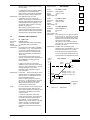
Figure 2.1:
Elite Series Technical Manual
Elite Series 400V Nominal and Re-rated Specifications
PDL Part No. 4201-180 Rev J
I[A]
(Note 2)
1
2
3
PDL Part No. 4201-180 Rev J
Elite Series 500V Nominal and Re-rated Specifications
Nema 12
IEC IP54
Electronics
Enclosure
4
5
Nema1
IEC IP20
Termination
Nema 12
IEC IP54
Electronics
Enclosure
6
7
Parallel
Drives
Note 1:
Note 2:
Note 3:
Note 4:
Note 5:
MOTOR kW
500V (Note 3)
@40°C
MOTOR HP
460V (Note 3)
I[A]
F>25Hz (Note 4)
MOTOR kW
500V (Note 3)
MOTOR HP
460V (Note 3)
RECOMMENDED
CABLE SIZING PER PHASE
FU S E S
PER PHASE
AWG/kcmil
(Notes 5-6)
A
(Notes 7-10)
mm2
ME-2D
2.5
1.1
1.0
3.1
1.5
1.5
14 to 12
2.5 to 4
6
ME-6D
6
2.2
3.0
7.6
4
5
12 to 10
2.5 to 4
16
ME-9D
9
4
5
12
7.5
7.5
12 to 10
2.5 to 4
25
ME-11D
11
5.5
7.5
14
9
10
10 to 8
4 to 6
32
ME-16D
16
7.5
10
21
11
15
10 to 8
4 to 6
40
ME-21D
21
11
15
27
15
20
10 to 8
4 to 6
50
ME-30D
30
18.5
20
37.5
22
25
8 to 6
6 to 10
80
ME-35D
35
22
25
45
30
30
6 to 4
10 to 16
100
ME-41D
41
22
30
52
33
40
3 to 1
16 to 25
100
UE-60D
60
37
40
75
45
50
6 to 3
16 to 36
150
UE-75D
75
45
50
94
55
60
4 to 1
20 to 50
200
UE-90D
90
55
60
112
75
75
3 to 1/0
25 to 50
200
UE-115D
115
75
75
144
90
100
1 to 3/0
50 to 95
300
UE-140D
140
90
100
175
110
125
2/0 to 4/0
70 to 120
300
UE-170D
170
110
125
205
132
150
3/0 to 300
95 to 150
350
UE-205D
205
132
150
250
160
200
250 to 400
120 to 240
350
UE-250D
250
160
200
305
200
250
350 to 500
185 to 2400
300
UE-305D
305
200
250
370
250
300
2 by 500
2 by 240
2 by 350
UE-370D
370
250
300
440
315
350
2 by 500
2 by 240
2 by 350
UE-440D
440
315
350
540
355
450
2 by 500
2 by 240
2 by 350
UE-540D
540
355
450
620
400
500
2 by 500
2 by 240
2 by 350
UE-620D
620
400
500
700
500
600
3 by 500
3 by 240
3 by 350
UE-700D
700
500
600
850
630
680
3 by 500
3 by 240
3 by 350
UE-760D
760
560
600
930
630
680
4 by 500
4 by 240
4 by 350
UE-930D
930
630
680
1070
710
845
4 by 500
4 by 240
4 by 350
UE-1070D
1070
710
845
1200
800
952
6 by 500
6 by 240
6 by 350
UE-1200D
1200
800
952
1000
1207
6 by 500
6 by 240
6 by 350
Frames 1-4 are UL/cUL approved to 480Vac.
Frames 5-7 & Parallel drives (inside delta) are UL/cUL approved to 500V.
Frames 1-4 are also available to suit a 230Vac (-20+10%) supply.
Current rating is constant across the voltage range.
Power rating applies to typical 4-pole machines only.
Check your motor specification before selecting.
Decrease linearly to nominal at 0Hz.
To comply with UL/cUL, use copper conductors only.
1470
Note 6:
Note 7:
Note 8:
Note 9:
Note 10:
Frame 1 maximum cable size for UL/cUL compliance is 5.3 mm2 (10WG).
Frames 1-2 input fuses must be of type gG (distribution) or gR/UR (semiconductor) .
Frames 3-4 input fuses must be type gR/UR (semiconductor).
Input fuses with UL recognition type gR/UR (semiconductor) are supplied pre-fitted for Frames
5-7 & Parallel drives.
If UL/cUL is to be complied with UL/cUL recognised fuses must be fitted.
Fuses must be selected to protect circuits with a maximum 200kA symmetrical short circuit
supply.
440Vac to 500Vac (-10% to +10%)
3 phase earthed neutral
Figure 2.2:
Nema 12
IEC IP54
Electronics
Enclosure
@ 50°C
MODEL
12
FRAME
Elite Series 500V Ratings
ENCLOSURE
RATING
Rated Voltage (VIN)
Supply type
Elite Series Technical Manual
440-500V (Note 1)
13
3
3.1
DESCRIPTIONS
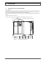
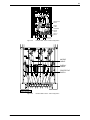
DESCRIPTION OF THE ELITE SERIES HARDWARE
3.1.1 Overview
The Elite Series range is a family of advanced AC induction motor controllers, presented in seven frame styles. All models are
available with IP54 ingress protection rating, suitable for installation in an environment where dust and splashing water may be
present. Alternatively, IP20 rated models are also available for the Microdrive Elite Series.
Ensure the correct model was specified for the intended environment. For detailed dimensional drawings, refer to Figures 3.1 to
Figure 3.3.
An electrical overview is shown in Figure 3.4.
10 (0.4)
Full details of mounting are provided in the Elite Series Getting Started Manual, Part No. 4201-179.
FRAME 3
All dimensions in millimetres and (inches)
FRAME 1 & 2
W
D
ON
START
RUN
4 (0.16)
OK
STOP
6.5 (0.26 )
30 (1.2 )
MODEL
FRAME 1 & 2
FRAME 3
Figure 3.1:
Elite Series Technical Manual
446.5 (17.6)
H
289.8 (11.5)
407 (16)
RESET
4808-013 REV I
H mm (ins)
W mm (ins)
D mm (ins)
Weight kg (lbs)
430 (17)
430 (17)
139 (5.5)
279 (11)
262 (10.3)
262 (10.3)
10-14 (22-31)
27 (60)
Microdrive Elite Series Dimensions
PDL Part No. 4201-180 Rev J
28 (1.1)
14
Lifting
Lugs
All dimensions in millimetres and (inches)
136 (5.4)
675 (26.6)
970 (38.2)
AC MOTOR CONTROLLER
168.5 (6.6)
116 (4.6)
313 (12.3)
347 (13.7)
4808-090 REV F
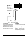
Net
Weight kg (lbs)
Packaged
Weight kg (lbs)
UE-60, UE-75
73.5 (162.04)
90 (198.42)
UE-90
77.5 (170.86)
94 (207.24)
UE-115, UE-140
80.5 (177.47)
97 (213.85)
MODELS
Figure 3.2:
Elite Series Technical Manual
Ultradrive Elite Frame 4 Dimensions
PDL Part No. 4201-180 Rev J
15
DIMENSIONS
W
500V
400V
MODELS MODELS mm (inches)
WALL MOUNT
BRACKETS
THROUGH
THE WALL
MOUNTING
UE-170D
UE-170
545 (21.5)
160 (353)
UE-205D
UE-210
545 (21.5)
160 (353)
UE-250D
UE-250
545 (21.5)
175 (386)
UE-305D
UE-305
965 (38)
320 (668)
UE-370D
UE-340
965 (38)
320 (668)
UE-440D
UE-420
965 (38)
350 (734)
UE-540D
UE-480
965 (38)
350 (734)
UE-620D
UE-575
1385 (54.6)
525 (1005)
UE-700D
UE-660
1385 (54.6)
525 (1005)
All dimensions in millimetres and (inches)
COOLING AIR
405 (15.95)
W
Net Weight
kg (lbs)
7 (0.28)
237 (9.33)
THROUGH
THE WALL
MOUNTING
1426 (56.14)
AC MOTOR CONTROLLER
4808-099 REV. E
Figure 3.3:
FLOOR MOUNT BRACKETS
COOLING AIR
FLOW
Ultradrive Elite Frames 5 to 7 Dimensions
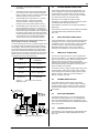
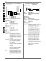
3.1.2 Power Conversion
3.1.3 Control Board
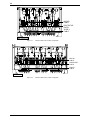
Key electrical circuit elements of the Elite Series range are
shown in Figure 3.5.
The control processor (control board) is supplied from the DC
bus via a DC to DC converter. In this way the control system
uses the DC bus to provide brief energy storage to achieve
significant immunity to small mains supply interruptions or
variations. Provision is made for energising of the control
board from an external power supply.
AC power is fed to the Elite Series input via external input
fuses. Here it is rectified to DC, filtered by chokes and
capacitors and reconverted ("inverted") to AC current at the
appropriate frequency, phase and voltage to supply the
motor.
DC bus terminals are provided for connection of dynamic
braking modules or direct supply from a DC source (external
soft charge needed for DC supply).
A Display Unit (3 LEDs, 16 x 2 character alphanumeric
display, 3 keys, and START and STOP-RESET push-buttons)
provides the primary user interface to the Elite Series. Detail
follows in Section 3.1.4. The Elite Series can be configured
from this Display Unit. Alternatively custom configuration can
be achieved by use of the external PDL Vysta® for Windows
software package, on a PC running Microsoft Windows.
The push-buttons can be configured to be inactive, or to
provide stand-alone START/STOP-RESET control.
Analogue and digital inputs and outputs are provided as
detailed in Section 3.1.5. More details can be found in the
Elite Series Getting Started Manual, Part No. 4201-179.
Elite Series Technical Manual
PDL Part No. 4201-180 Rev J
16
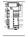
+HVDC
U
V
W
L1
L2
L3
POWER ELECTRONICS
ENCODER
MOTOR
PE
-HVDC
PE
DISPLAY
ON
RUN
+24V
OK
PTC/TRIP
INPUT
DATA
START
0V
STOP
RESET
SHAFT ENCODER INPUT
FOR DIFFERENTIAL OR
SINGLE-ENDED ENCODERS
+5V / +24V
USER +24V I/O 500mA
SUPPLY
0V
PROGRAMMABLE
ANALOGUE
INPUTS
POT.
SUPPLY
A
_
A
10mA
0-10V
±10V
B
_
B
0-20mA 4-20mA
COMMON
CONTROL
0V
BOARD
RLY 1
MFI 1
PROGRAMMABLE
MULTI-FUNCTION
INPUT SWITCHES
MFI 2
MFI 3
RLY 2
MFI 4
MFI 5
PROGRAMMABLE
RELAY OUTPUTS
RATING 250Vac/30Vdc 2A
NON-INDUCTIVE
RLY 3
MFI 6
+24V
PROGRAMMABLE
ANALOGUE OUTPUTS
0-10V, ±10V @5mA MAX.
4-20mA, 0-20mA
0V
ISOLATED RS485
SERIAL
COMMS. RS232
FIBRE OPTIC OUT
FIBRE OPTIC IN
4808-018 Rev J
Figure 3.4:
Elite Series Technical Manual
Elite Series Electrical Overview
PDL Part No. 4201-180 Rev J
17
B
DYNAMIC BRAKE
RESISTOR
(OPTIONAL)
L3
RFI FILTER
L1
L2
RFI FILTER
+HVDC
U
V
W
PE
PE
-HVDC
RECTIFIER
INVERTER
4808-093 Rev C
Figure 3.5a:
Power Electronics - Microdrive Elite Frames 1 & 2
L2
L3
RFI FILTER
L1
RFI FILTER
+HVDC
U
V
W
PE
PE
-HVDC
RECTIFIER
INVERTER
4808-094 Rev C
Figure 3.5b:
Power Electronics - Microdrive Elite Frame 3
L3
RFI FILTER
L1
L2
RFI FILTER
+HVDC
U
V
W
PE
PE
-HVDC
RECTIFIER
INVERTER
4808-095 Rev B
Figure 3.5c:
Power Electronics - Ultradrive Elite Frame 4
RFI
SUPPRESSION
+HVDC
L1
L2
L3
U
V
W
PE
PE
- HVDC
RECTIFIER
INVERTER
4808-098 Rev E
Figure 3.5d:
Elite Series Technical Manual
Power Electronics - Ultradrive Elite Frames 5 to 7
PDL Part No. 4201-180 Rev J
18
Power
On
No Fault
(Flashing=Fault)
Drive
Running
Alternatively, the START push-button can be configured to be
in parallel with an external START switch, and the STOPRESET push-button in series with an external STOP-RESET
switch.
Backlit LCD
Display
Details on configuring these push-buttons are given in
Section 9 of this manual.
Status Line
Control Line
SCREEN ORGANISATION
Screens can be arranged in folded format. Each screen
group has a main screen with the group identifying letter and
description. Folded under this main Screen can be a number
of subscreens, each of which has a single parameter or
mode for viewing or adjustment. These subscreens cannot
be viewed until unfolded using the “∗” key. The entire set of
screens is known as a Screen List.
Control Keys
4808-040 Rev D
Figure 3.6:
The Display Unit and Keys
3.1.4 The Display Unit and Controls
The Display Unit of the Elite Series may be removed from the
front of the unit, and refitted in any orientation, or mounted
remotely from the unit (up to three metres away). The
display is in an IP54 enclosure, thus is protected against
ingress of dust and moisture.
The following descriptions refer to Figure 3.6.
THE LED INDICATORS
Once unfolded, some subscreens in a Screen List have a
numerical parameter which may be adjusted. Others may
have a list of options, with each option separately viewable
and selectable.
Each screen or subscreen has a viewing attribute. This
attribute defines if the screen is “read only”, “read–write” or
“hidden”.
Note that the main screen or subscreen will be visible only if
its attribute is configured to be “read” or “read-write”. If a
screen is configured as “hidden” it will only be visible when
the Elite Series is in “commissioning” mode.
Details on controlling these screens and adjusting
parameters and modes are given in Section 7 of this manual.
Full details of the Screen List are given in Section 9 of this
manual.
ON
Indicates mains power is supplied to the Elite Series
Display.
RUN
Indicates the Elite Series is running (driving a motor).
CUSTOMISATION OF CONFIGURATION
OK
Steady: Indicates that the Elite Series is operating
normally.
OK
Flashing: Indicates that the Elite Series has tripped
on fault protection.
The Elite Series Control Board processor has a number of
logic and processing blocks integrated into the firmware.
These can be configured using PDL VYSTA® for Windows
to enhance the existing default configuration, or for
configuring a completely new control system. These blocks
include logic gates, counters, timers, analogue signal
processors, PID controllers, inputs and outputs.
THE LCD DISPLAY
The Elite Series has a sixteen character by two line (16x2)
LCD display.
The lines each have different functions:
•
The STATUS LINE is always present and shows the
Elite Series status, the output current or torque and
the motor speed.
•
The CONTROL LINE of the display is used to view
and/or adjust the many parameters of the Elite
Series.
THE CONTROL KEYS
The “+” and “–” keys are used to scroll between screen
groups. The “∗” key can be used to unfold a screen group,
then the “∗” and “+” or “–” keys used to adjust the parameter
or mode on display on the control line. Refer to Section 7 of
this manual for full details of screen organisation and control.
THE START AND STOP-RESET PUSH-BUTTONS
These push-buttons may be configured to enable starting and
stopping of the motor from the display unit if required, and
also to reset the Elite Series in the event of a fault trip.
Elite Series Technical Manual
To suit any custom configuration, a custom Screen List can
also be designed. This Screen List may be a modified
version, or a foreign language version, of the default Screen
List provided.
More details on customisation of control are given in Section
8 of this manual.
SECURITY PROTECTION
For reasons of security, the Elite Series must be in
commissioning mode (Screen Z) before certain
adjustments can be made. Some adjustments also cannot
be made unless the Elite Series is in a OFF state (this is for
safety reasons).
If commissioning mode is enabled, any user can adjust all
settings and configurations. To enable this mode, scroll to
Screen Z, and enter the correct password. Further details
are given in Section 9 of this manual.
3.1.5 Control Inputs and Outputs
Figure 3.7 provides the complete electrical specification of all
Elite Series control inputs and outputs. Each input and
output is individually described below. Further information
(including specific examples of connection) is presented in
the detailed descriptions of the relevant control screens.
PDL Part No. 4201-180 Rev J
19
For further connection information to these terminals, refer to
Elite Series Getting Started Manual, Part No. 4201-179.
Terminals T1 to T7 - Configurable Relay Outputs
These are low power relay contacts offering operation at
signal or 250Vac levels (referenced to the protective earth PE). Selection of their function is made through Screen
Group O. Avoid settings which cause the relays to switch
excessively as this will reduce their life expectancy. The
software places a 250ms minimum pulse width to prevent
relay chatter.
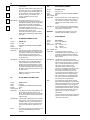
Terminals T8, T9 - Dynamic Brake Control
If a dynamic brake is to be installed in conjunction with the
Elite Series, it can be controlled from these terminals. For
drives up to and including ME-22.5, these terminals will be
internally connected to the inbuilt dynamic brake transistor.
Dynamic brake resistor thermal protection can be configured
from Screen Group D.
Terminal T10 to T12 - Display Unit
The connections to the Display Unit are made via these
terminals. The Display Unit may be removed from its
position within the drive and be mounted remotely, The
maximum allowable length of wiring is 3 metres.
Terminals T13 to T18 - Multi-function Inputs
The function of these inputs can be programmed from the
keyboard, from Screen Group I. Alternatively they can be
customised via the PDL Vysta® for Windows software running
on a personal computer.
Screen all control cables
O/P
Relay 1
Relay Outputs
Rating
250Vac /
30Vdc
2A
Non-inductive
T1
T2
T3
O/P
Relay 2
O/P
Relay 3
275Vac
T4
3x
Programmable
Volt Free
Relay Outputs
2 x N.O.
1 x C.O.
275Vac
275Vac
T5
T6
275Vac
T7
T8
External
Dynamic
Brake
Switch
T9
External Dynamic Brake Control
+24V
ON
RUN
OK
RED
YELLOW
Display
START
STOP
GREEN
T10
T11
Int.+24V
Display
Data
RESET
T12
T13
Programmable
Inputs
Load
Current: 3mA
Max. Low
Threshold: 7.5V
Min. High
Threshold: 15V
Control
Voltage: +24/0V
T14
T15
T16
T17
16k5
Active
Low
Active
High
16k5
16k5
16k5
6x
Multifunction
Inputs
16k5
16k5
T18
Motor PTC
or external trip input
T19
Active Low
T20
Active High
T21
Fibre Optic Output
FO
Motor
PTC Input
+24V
Figure 3.7a:
4808-037 Rev I
Control Terminals T1-T21
Their operating format may be set for active high or active
low. These inputs are factory preset for active high operation
(that is, they are internally connected to bias low). Sampling
rate:4ms
Terminal T22 - Analogue Output 0V Connection
Terminal T19 - External trip/Motor PTC
Terminals T23, T24 - Configurable Analogue
Outputs
This is a digital input committed to causing a protective trip
should the resistance between this terminal and the selected
common exceed 2.1kOhms. This is characterised for a set
of standard motor PTC thermistors. The operating mode of
the input can be changed between active high and active low.
Opening this circuit will always trip the Elite Series, removing
power from the motor. Open this circuit in the event of a
“loss of control” situation. Sampling rate: 4ms
Terminals T20, T21 - Input Switch 0V & +24Vdc
Connections
These terminals provide a return point for the seven digital
inputs connected to terminals T13 to T19. If active high is
selected, the common points of the switches connect to
Terminal T21. If active low is selected, the common points of
the switches connect to Terminal T20.
This 0V is a suitable return point for the two analogue outputs
connected to Terminals T23, T24. This ground is internally
linked to the other control grounds with the exception of T40.
These two analogue outputs may have their formats and
sources configured. Formats can be 0 to 10Vdc, -10 to
+10Vdc; 5mA max or 0 to 20mA or 4 to 20mA. Configuration
is done from Screen Group O. Accuracy: ± 2%; Resolution: 8
bits.
Terminal T25 - Analogue Input 0V Connection
This 0V connection is a suitable return point for the two
analogue outputs connected to Terminals T26, T27. This
ground is internally linked to the other control grounds with
the exception of T40.
Terminals T26, T27 - Analogue Inputs
These inputs are configurable as to their function, also their
formats and scaling may be set. Formats can be 0 to 10Vdc,
-10 to +10Vdc, 0 to 20mA or 4 to 20mA. Configuration is
done from Screen Group I. Accuracy: ± 2%; Resolution: 10
bits.
Terminals T28, T29 - Potentiometer Supply
A 10mA constant current source provides up to 10Vdc for a
1k Ohm potentiometer.
Terminals T30 - +5Vdc
This terminal is provided for the encoder power supply.
Maximum load is 100mA.
Elite Series Technical Manual
PDL Part No. 4201-180 Rev J
20
Terminals T31 to T34 - Incremental Quadrature
Encoder Inputs
Screen all control cables
The Elite Series is designed to accept input from a standard
quadrature encoder designed to operate from +5Vdc to
24Vdc and having single ended open collector outputs,
push-pull open collector outputs, or differential logic driver
outputs. This encoder is only required if operating in Closed
Loop Vector control mode. The encoder type and pulses
per revolution may be configured from Screen Group N.
T22 0V
Analogue
T23 Output 1
Analogue
T24 Output 2
250 Ohm
T25 0V
Format:
0V to +10V
-10V to +10V
4 to 20mA
or 0 to 20mA
T28 10mA to feed
1k Ohm pot
Analogue
T26 Input 1
Analogue
T27 Input 2
250 Ohm
10mA
Terminal T35 - Encoder 0V
This terminal is provided for the encoder power supply 0V
return. This ground is internally linked to the other control
grounds with the exception of T40.
T29 0V
Encoder
+5V
T30
T31 A
A
--
2k7
These are provided for powering of user controls, encoder
power supply or for back feeding a backup power supply to
energise the control board in the event of mains failure.
This output is fuse protected.
T32 A
2k7
T33 B
B
2k7
T34
Decoder
Int.
+24Vcc
Maximum output current capability: 500mA
Minimum input current capacity of backup supply: 1A.
Backup supply voltage: 24Vdc ±10%
Encoder
Single-ended/
Differential
Terminals T38 to T42 - RS232 / RS485
Connections
30V
User
+24Vcc
Fuse
F1
T35
RS
485
T38 RS485 A
T39 RS485 B
RS
232
RS232 / RS485
T41 RS232 Rx
T42 RS232 Tx
4808-038 Rev H
FI
Screening - it is essential that all control inputs and
analogue outputs are screened. There are no exceptions if
you expect reliability!
0V
+24V In/Out
T36 User
500mA max.
T40
Iso
IMPORTANT NOTES REGARDING RELIABILITY
OF CONTROL CIRCUITS
Screening
-B-
Incremental
Quadrature
Encoder
Max. Freq.
200 kHz
T37 0V
+5V Iso
Rx
Tx
These terminals are provided for serial communications
connections, for control, monitoring or configuration from a
PC or other remote host. These terminals are optically
isolated from the Elite Series potential.
+5V max.100mA
2k7
Decoder
Terminals T36, T37 - User 24Vdc In/out, 0V
Format:
R L >500 Ohm:
0V to +10V or
-10V to +10V; 5mA max
R L <500 Ohm:
4 to 20mA
or 0 to 20mA
Figure 3.7b:
3.2
Fibre Optic Input
Control Terminals T22-T42
DESCRIPTION OF THE ELITE SERIES
CONTROL SYSTEM
3.2.1 Structure of the Inputs and Outputs
Cable Separation
The following descriptions refer to Figure 3.8.
Do not run control signals together with power input or
output cables to the motor - space at least 300mm away,
and cross at right angles.
ANALOGUE INPUTS
Relay Signals
Output relay signals do need to be screened. If power
switching, do not include output relay signals in the same
screened cable with control signals. Do not overload relays.
Switch Inputs
Switch (multifunction) Input circuits are designed for 24Vdc
operation. Do not apply any other voltage.
Two analogue inputs are provided. The format and scaling of
these inputs are configurable from the front panel.
The format of each is configurable by Screens I6a, I6d,
without links, to be 0 to 10Vdc, –10 to +10Vdc, 0 to 20mA or
4 to 20mA.
Analogue Processing -Screen I6g may be used to introduce a
zero baud to the analogue signal. This is used to ease
setting of absolute zero values. Scaling determines the
percentage (of motor speed or torque) demanded by the
minimum and maximum settings. This is done by Screens
I6b, I6c, I6e, I6f.
Earthing of Control 0V
To comply with the requirement of a Class 1 earthing
system, the Elite Series control 0V must be linked to earth
at some point. Connection of multiple earth points may
cause earth loops and should be avoided. An earth link is
provided, and must be removed if not required. Removal
will allow the 0V point to float up to ±50Vdc (30Vac) from
chassis earth.
More comprehensive connection information is given in the
Elite Series Getting Started Manual (PDL Part No.
4201-179).
Elite Series Technical Manual
OUTPUTS
Potentiometer Supply - A 11mA constant current source
provides 10V to a 1kOhm potentiometer.
Relay Outputs - Each of three relay outputs may be controlled
from a large number of sources using Screens O2a, O2c,
O2e. Each may be individually inverted. RLY1 is of
changeover configuration, RLY2 and RLY3 have normally
open contacts.
Analogue Outputs - Each of the two analogue outputs can
have its source, format and scaling configured from the
PDL Part No. 4201-180 Rev J
21
display unit. Each analogue output can have its format
configured, with a choice of 0 to 10Vdc (unipolar), –10 to
+10Vdc (bipolar), 0 to 20mA or 4 to 20mA using Screens O1a
to O1h.
COMPARATOR
Comparator -Two software comparators allow relay outputs to
respond to analogue levels. The comparators may be
individually selected to any analogue output source.
Individual ON and OFF levels may be set. A window function
may also be selected. Configuration is by Screens C1 to C6.
Additionally a special torque limit (L8 MAX REGEN) is
provided which controls the maximum level of regenerated
power.
TORQUE REFERENCE PROCESSING
The torque set point may be selected from eight possible
torque references. Additionally a second alternative reference
selection may be made. The chosen torque set point may
optionally be inverted. Minimum and maximum torque limits
are provided. An optional torque filter completes the
processing. The torque set point is then routed to the flux
vector controller source selector.
SWITCH INPUTS - MULTI-FUNCTION INPUTS
Switch Inputs - Six switch inputs are provided. These inputs
set digital levels and are collectively known as Multi-function
Inputs (MFI).
The multi-function inputs are factory set from the Display Unit
to bias low for active high switching, which is considered to
be a "fail-safe" mode. Alternatively the inputs may be set for
active low switching using Screen I7b.
The six multi-function inputs perform control functions
according to the input mode selected on Screen I7a. When
certain modes are selected the function of some (or all) of the
inputs may be individually programmed to act as one of a
wide range of possible controls, by use of Screens I7c to I7h.
The switch inputs are processed together with keyboard
controls (and set point references - multi-references) to
provide a number of internal digital controls as well as the
control of two analogue reference signals (motorised
potentiometer and multi-reference).
3.2.2 Structure of the Motor Control System
Referring to Figure 3.9, unless the Elite Series is operating
in V/Hz mode, the structure of the Elite Series control system
may be considered as a torque controller, (the flux vector
control system), the input of which selects either a speed
referencing or torque referencing processor. This torque
controller may be operated with a shaft encoder mounted on
the motor for the best response and low speed operation.
Alternatively it may be used without an encoder (Open Loop
Mode control mode) for less critical applications.
SPEED REFERENCE PROCESSING
The speed set point may be selected from eight possible
sources. Additionally a second alternative reference selection
may be made. The chosen speed reference may optionally
be inverted. At this point the speed set point may be
overridden by fixed speed demands such as inch references.
Minimum and maximum speed limits are provided followed by
Skip speeds (set by Screens L10 to L12) to allow the user to
avoid mechanical resonances. The speed set point is then
processed by the acceleration, deceleration and speed filter
controls according to various rate (R) screen settings.
As the flux vector controller is a torque control system, the
speed control signal cannot be applied directly to the vector
controller. Instead it must be applied to a speed feedback
loop, the output of which is a torque demand. Thus, the
speed set point is finally applied to a PID speed controller.
The set point is compared to the actual speed, fed back from
the shaft speed encoder. The resulting torque command
signal is routed to the flux vector controller source selector.
PROCESS CONTROL
The inclusion of a full three term PID regulator allows the Elite
Series to perform process control (e.g., constant pressure
pumping etc.). External auto/manual selection is also
available to assist during start-up conditions. Refer to Figure
3.10
THE FLUX VECTOR (TORQUE) CONTROLLER
Unlike conventional AC motor speed controllers, the Elite
Series is primarily a torque control system. The flux vector
control method requires complete knowledge of motor
parameters, together with feedback of the rotor shaft speed.
A high resolution encoder fixed to the motor shaft directly
feeds back accurate indication of motor speed. This is
scaled according to the pulse per revolution rating of the
encoder (typically 2000 ppr) and the motor rated speed. The
encoder additionally feeds back speed to the speed control
loop, and overspeed protection override.
To ensure accurate operation, all the motor and shaft
encoder parameters must be entered using the N screen
group. Also vector loop tuning parameters (the X screens)
must also be entered. The X screens can most easily be set
up by using the autotuning facilities available (Screen X2).
Open Loop mode operation is also available, where a motor
shaft encoder is not used. A reduction in performance may
be expected when running in this mode. Torque control is not
available when operating in Open loop Mode.
The source of the torque demand reference is selected
according to the desired (speed or torque) operating mode.
The torque reference is subject to overspeed limits set on
Screens L2 and L3, and minimum and maximum torque limits
set on Screens L4 and L5.
Elite Series Technical Manual
PDL Part No. 4201-180 Rev J
22
Elite Series Technical Manual
SWITCH INPUTS
OUTPUT TERMINALS
I7c MFI1 SEL
I7d MFI1 SEL
I7e MFI2 SEL
I7f MFI3 SEL
I7g MFI4 SEL
I7h MFI5 SEL
I7b POLARITY
RLY3
O2e RLY3 SEL
I7a I/P MODE
O2c RLY2 SEL
INTERNAL CONTROL
SIGNAL OUTPUTS
STOPR
O2a RLY1 SEL
RELAY
SOURCES
22
/
ALTERN ACCEL
Figure 3.8:
MFI1
MFI2
MFI3
MFI4
MFI5
MFI6
INVERT
ALL
INPUTS
6
/
5
/
MULTI-FUNCTION
INPUTS
PDL Part No. 4201-180 Rev J
Structure of the Elite Series Input/Output Processing System
START
INPUT MODE
CONTROLLER
AND
START/STOP
LOGIC
INVERT SPEED
INVERT TORQUE
WINDOW COMP
SP/TQ MODE
C1 COMP SEL
REMOTE/LOCAL
COMP 1 OUTPUT
C2 ON
C3 OFF
MOTOR POT
ANALOGUE
OUTPUTS
18
/
POTENTIOMETER SUPPLY
+10V, 10mA
ANALOGUE INPUTS
I6a AIN1
0-10V
±10V
4-20mA
0-20mA
I6b AIN1 LO
I6c AIN1 HI
M1
M2
M3
M4
M5
M6
M7
MREF1
MREF2
MREF3
MREF4
MREF5
MREF6
MREF7
FIBRE
OPTIC
O3a FIBRE O/P
O1e A02 O/P
O1f AO2
O1a A01 O/P
18
/
I6g ZERO BAND
O1g AO2 LO
O1h AO2 HI
0-10V
±10V
4-20mA
0-20mA
SCALE
FORMAT
AO2
AIN1
FORMAT
COMP 2 OUTPUT
C5 ON
C6 OFF
18
/
MULTI REF.
R
RLY1
O2b RLY1 INV
INCH
3
/
STOP
RESET
O2d RLY2 INV
C4 COMP 2 SEL
2
/
A1 LOCAL MODE
I1 LOCAL ST/STP
RLY2
ALTERN REF
18
/
PROGRAM
INPUTS
O2f RLY3 INV
SCALE
O1b AO1
AIN1 SCALED
I6d AIN2
0-10V
±10V
4-20mA
0-20mA
+
AIN1+2 SCALED
I6e AIN2 LO
I6f AIN2 HI
O1c AO1 LO
O1d AO1 HI
0-10V
±10V
4-20mA
0-20mA
SCALE
FORMAT
AO1
AIN2 SCALED
AIN2
FORMAT
SCALE
I8a FI LO
I8b FI HI
4808-047 REV F
FIBRE
OPTIC
- DIGITAL SIGNALS
SCALE
- ANALOGUE SIGNALS
- TERMINALS
INPUT PROCESSING
OUTPUT PROCESSING
Elite Series Technical Manual
Figure 3.9:
PROCESS CONTROL
A2 LOCAL TQ
NULL = 0
FIBRE
MOTOR POT
MULTI REF.
AIN1+2 SCALED
AIN2 SCALED
AIN1 SCALED
TORQUE REFERENCE
PROCESSING
PROCESS CONTROL
A3 LOCAL SP
NULL = 0
FIBRE
MOTOR POT
MULTI REF.
AIN1+2 SCALED
AIN2 SCALED
AIN1 SCALED
SPEED REFERENCE
PROCESSING
I3 REF T
I5 AREF T
TORQUE REFERENCE
SELECTION
I2 REF S
I4 AREF S
SPEED REFERENCE
SELECTION
ALTERN
REF
ALTERN
REF
INVERT
TORQUE
X
INVERT
SPEED
X
L4 MIN T
L5 MAX T
INCH
SPEED
SETPOINT
OVERRIDE
LCD LINE 2
A4 T=
INVERT
INCH
SKIP
SPEEDS
L2 MIN S
L3 MAX S
X4f Kp w
X4g Ki w
X4h Kd w
X5i Kfw
PID
FB
SPEED
CONTROLLER
TORQUE
CONTROL
SPEED
LOOP
ALTERN.
ACCEL
SP
- TERMINALS
- ANALOGUE SIGNALS
- DIGITAL SIGNALS
TORQUE
FILTER
R8 TQ FILT
STOPR
ACCEL
CONTROL
+ SRAMP
R1 ACC
R2 DEC
R3 AACC
R4 ADEC
R5 BRK S
R6 STOPR
R7 SP FILT
LCD LINE 2
A4 S=
L3 MIN S
L3 MAX S
L4 MIN T
L5 MAX T
MODE
SOURCE
SELECTOR
LCD LINE 1
T=
LIMIT
CALCULATIONS
INCREMENTAL
ENCODER
n
N1 MTR CUR
N2 MTR VOLT
N3 MTR FRQ
N4 MTR KW
N5 MTR RPM
X1 CTRL TYPE
X3a Lm
X3b Rs
X3c Rr
X3d SIGMA
X3e FLD WEAK
X5g Kp I
X5h Ki I
4808-046 Rev J
M
TACHO INPUT
A A B B
ENCODER
SCALING
N5 MTR RPM
N8 ENCODER
FLUX
VECTOR
TORQUE
CONTROLLER
BUS VOLTS
CURRENT
POWER
LCD LINE 1
S=
L8 MAX REGEN
OVERSPEED
OVERRIDE
FLUX VECTOR
(TORQUE) CONTROLLER
23
Structure of the Elite Series Motor Control System
PDL Part No. 4201-180 Rev J
24
FEEDBACK
SELECTION
P2 FB SRC
AIN1 SCALED
P3 Kc
AIN2 SCALED
P5 Td
P4 Ti
P7 INVERT
AIN1+2 SCALED
FIBRE
SETPOINT
SELECTION
P1 PR SRC
PID
PROCESS CONTROL
AIN1 SCALED
AIN2 SCALED
AIN1+2 SCALED
4808-070 Rev F
FIBRE
LCD Line 2
P6 Error=
A3 LOCAL SP
MULTI REF.
MOTOR POT
Figure 3.10:
Elite Series Technical Manual
Process Control
PDL Part No. 4201-180 Rev J
25
4
APPLICATION RECOMMENDATIONS
4.1
THE MOTOR
2.1, if the Elite Series is to be operated in an environment of
an ambient temperature not exceeding 40°C.
4.1.1 Sizing the Motor and Elite Series
The Elite Series is suitable for controlling all standard three
phase induction motors. In sizing the Elite Series, the torque
requirements of the load must first be assessed. Under flux
vector control conventional induction motors are able to
provide at least 200% of rated torque (often 250%). Choose
a motor capable of supplying the required torque and a Elite
Series capable of supplying the motor's current requirements.
In applications requiring high peak torques, the Elite Series is
required to supply current approximately in proportion to the
torque. The Elite Series should be chosen according to its
short term overload limit of 150% (30 seconds).
Note: Figure 4.1 is presented as a guide only, refer to Figure
2.1 for the 400V ratings and Figure 2.2 for the exact ratings
of the 500V models.
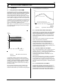
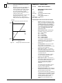
TORQUE (%)
100
80
AREA OF CONTINUOUS OPERATION
60
40
20
TORQUE CURVE FOR MAXIMUM TEMPERATURE RISE
TORQUE CURVE FOR THE RATED TEMPERATURE RISE (40˚C AMBIENT)
0
0
20
40
60
80
100
120
140
160
180
200
MOTOR RATED FREQUENCY (%)
4807-300 Rev. C
Figure 4.2:
Typical Motor Thermal Derating
4.1.2 Operation Above Motor Rated Speed
Inverter
Current (%)
Short Term Overload 30 seconds at 50˚C
60 seconds at 40˚C
Continuous Rating at 40˚C - Elite Frames 1 to 4(All)
125
Continuous Rating at 40˚C - Elite Frames 5 to 7(400V)
110
Continuous Rating at 50˚C - (All Models)
100
150
75
50
25
0
0
25
50
75
400
Hz
4808-048 Rev F
Figure 4.1:
Elite Series Thermal Overload
Characteristics
In applications operating continuous loads or providing
significant torque at low speeds, the motor must be chosen
on a basis of continuous dissipation. It may be necessary to
oversize, or force cool the motor for applications operating
with significant torque at low speeds (Figure 4.2). In such
applications the Elite Series should be chosen according to
its continuous rating.
For pump and fan applications having a quadratic torque
requirement where a high overload margin is not usually
required, the Elite Series may be re-rated according to Figure
Elite Series Technical Manual
The Elite Series can be operated above motor rated speed in
V/Hz and closed loop mode only, however the torque that is
able to be generated declines (1/f) as there is insufficient
voltage to provide correct stator flux. The torque response
also reduces significantly in this mode of operation for the
same reasons.
Check that the motor is suitable for operation above rated
speed. Consult the motor manufacturer.
A popular solution to achieve a wider speed range is to
reconfigure the motor for lower voltage operation (e.g.,
connect a 400Vac star motor as a 230Vac delta , or
specially wind the motor). Full performance is achieved at
increased speeds (until the supply voltage is reached), at the
penalty of increased motor current.
4.1.3 Operation of More Than One Motor
When running the Elite Series in Open or Closed Loop mode,
operation of more than one motor from the Elite Series is
generally impractical. In certain applications utilising identical
motors with identical loads (e.g., load sharing or
mechanically locked) connection of more than one motor
may be possible.
When running the Elite Series in V/Hz Mode , it is possible to
run more than one motor in parallel off one Elite Series. If
running parallel motors, the rating of the Elite Series should
exceed the sum of the individual motor currents. Each motor
will require individual thermal protection. Performance will be
reduced.
4.1.4 Thermal Protection of the Motor
The Elite Series maintains a thermal model of the motor as
its primary means of detecting overload and providing
protection. Nevertheless the use of a temperature protecting
PTC embedded in the motor windings provides ultimate
protection and is recommended. The thermal model will not
PDL Part No. 4201-180 Rev J
26
be effective if the Elite Series is running more than one
motor.
will also accept input pulses from an encoder operating off a
supply up to 24Vdc.
4.1.5 Large Frame-size Motor Considerations
4.2.2 Connection of the Encoder
Large frame-size motors (typically greater than 315 frame)
have additional installation requirements when used with AC
motor controllers. These motors may exhibit rotor voltage
build-up due to parasitic capacitance. Unless protective
measures are taken, this voltage may discharge through the
anti-friction bearings possibly leading to degradation of the
bearing via electrical discharge machining (EDM).
The encoder orientation shown in the drawings in this manual
(i.e., the connection of the A and B outputs) assumes the
encoder is to be connected directly to the non-drive end (nonshaft end) of the motor and that motor wiring orientation is
normal (motor terminals U1, V1 and W1 are connected to
Elite Series terminals U, V, W, respectively). In this case, an
increasing count (Screen Z9 ) should correspond to rotation
in the positive direction (motor shaft rotates clockwise when
the motor is viewed from the drive end), in response to a
positive speed reference.
The preferred solution is to fit insulated bearings (or an
insulated bearing housing) with a rotor earthing brush.
Careful selection of the rotor earthing brush is required, as
this brush must provide a low impedance earth for high
frequency pulses. Rotor shaft earthing brushes are now
commercially available to suit this low voltage, low current
application. These brush systems are designed for long life
with minimal maintenance. Contact PDL Electronic or its
agent for further information on suitable earthing brushes. An
alternative solution is available from PDL Electronics in the
form of PDL’s EDM Filter. The EDM filters out the common
mode voltage applied to the motor. Contact PDL Electronics
or its agent for further information on the EDM Filter.
4.2
THE ENCODER
4.2.1 Choice of Encoder
If the Elite Series is to be used in Closed Loop Vector control
mode, a shaft encoder will need to be connected to the
motor. A specification for a suitable encoder for a 50 or 60Hz
motor is:
Encoder type:
Incremental, quadrature (bi-phase), differential or singleended output. Push-pull output preferred to maximise range.
Recommended ppr:
1000 to 2000 ppr per motor pole pair, for directly driven
encoder
Minimum ppr:
500 ppr per motor pole pair (4 pole motor = 1000 ppr)
Supply requirement:
5Vdc, 100mA maximum
The shaft encoder should be fitted directly to the motor (using
a flexible coupling) or indirectly via a toothed (zero slip) belt
drive or similar. There must be zero slip or backlash, and
high shaft loads or loose couplings must be avoided.
The encoder MUST be connected using shielded twisted
cable. The shield should be earthed at the Elite Series end
only, to avoid the possibility of earth loops. The maximum
cable length is inversely proportional to the required
maximum pulse rate. A push-pull output encoder gives a
better range than a single ended open collector type, and is
recommended for cable runs exceeding 30 metres. If using
an open collector type of encoder, when wired with typical
shielded cable with capacitance of 200pF/metre, the product
of cable length (metres) x max. frequency (kHz) should not
exceed 1500.
If the encoder direction is inverted (e.g., by mounting at the
drive end or using an inverting belt coupling), A and B, or for
a differential encoder, A and A signals should be swapped.
Refer Figure 5.4.
4.3
SWITCHING
4.3.1 Power Switching
Generally it is better practice to leave electronic equipment
(including the Elite Series) permanently connected to the
mains supply. Switching the mains on and off to control the
Elite Series is bad practice and should be avoided (use the
control terminals). Mains switching must not occur more
often than once every five minutes to avoid overheating the
charging circuits.
4.3.2 Motor Switching
Because the Elite Series acts as a variable frequency
(including DC) current source :WARNING:
Motor isolation MUST NOT BE OPENED
while the Elite Series is running.
Although the Elite Series will not be damaged, standard
industrial switchgear (AC1 or AC3) is not designed to operate
at or near DC conditions, and there is great danger of
damage or fire due to arcing under these conditions.
4.4
TORQUE AND SPEED CONTROL MODES
4.4.1 Torque Control Mode
Unlike conventional AC motor speed controllers, the Elite
Series is primarily a torque controlling device. When used in
Closed Loop Vector torque mode, a reference torque
demand signal sets the output torque level which the Elite
Series will try to achieve from the motor. This level may be
positive or negative and is quite independent of the motor
speed (within speed limits). Web control systems which
require constant tension applied to the web, regardless of
speed, are a typical torque control application.
While in torque mode, speed limits are used to limit
overspeed such as may occur from temporary loss of load
(e.g., a web break in the above example). The speed
reference signal is disregarded while in torque control mode.
A differential output encoder has a high common-mode noise
rejection capability, thus is recommended for electrically
noisy environments. The encoder inputs to the Elite Series
Elite Series Technical Manual
PDL Part No. 4201-180 Rev J
27
To run in torque control mode, it is necessary to employ
Closed Loop Vector control mode and use a shaft encoder
on the motor.
DB RESISTOR
POWER RATING
(MIN-kW)
ELITE SERIES
DB RESISTOR
MINIMUM (Ohms)
ME-2.5
500
1.1
ME-2D
500
1.4
ME-6.5
180
3
ME-6D
180
3.8
ME-10.5
130
4
ME-9D
130
5.3
ME-12
100
5.3
ME-11D
100
6.7
ME-18
50
10.6
ME-16D
50
13.5
ME-22.5
50
10.6
ME-21D
50
13.5
4.4.2 Speed Control Mode
In Open Loop or Closed Loop vector mode PID settings are
used to adjust the response of the speed control loop. Apart
from this, speed control is implemented and settings made in
a similar way to conventional AC drives.
A reference speed control signal sets the output speed which
the Elite Series will try to achieve at the motor. The direction
may be positive or negative, and is independent of load
torque (within torque limits).
While in speed control mode, torque limits are used to limit
over- torque such as may occur due to process changes or
fault conditions.
For best performance in speed control mode, employ Closed
Loop Vector control mode and use a shaft encoder on the
motor. This gives improved speed regulation, faster dynamic
response, and full torque capability at zero speed.
If such high performance is not required, Open Loop Mode or
V/Hz control mode may be employed. In these modes a
shaft encoder on the motor is not necessary.
4.4.3 Switching Between Torque and Speed
Control Modes
When switched, transition from torque control mode to speed
control mode and the inverse, is achieved without
discontinuity (i.e., smoothly). Torque Control mode may
only be selected when the Elite Series is used in Closed
Loop Vector control mode.
4.5
DYNAMIC BRAKING
Regeneration is achieved through the motor being driven by
the load (e.g., lowering crane hoists or rapid deceleration of
high inertia loads). While being driven, the motor acts as a
generator and energy is transferred back into the DC bus
capacitors of the Elite Series. In its standard form the Elite
Series can only dissipate this energy as losses and so can
only provide limited braking of 5-10%.
Where higher levels of braking are needed, an additional
dynamic brake module must be fitted. Dynamic brakes are
controlled power switches which are used to dump energy
from the DC bus into resistive loads. Generally such brakes
and resistors must be sized to suit the requirements of the
application according to considerations of both peak and
continuous power dissipation requirements. Refer to the
supplier for more information regarding specific dynamic
brake modules, or to the dynamic brake manual if already
supplied.
The Elite Series frame 1 to 2 models have a dynamic brake
transistor built into the unit. Simply connect the appropriately
sized resistor between the positive DC bus terminal “+” and
the dynamic brake resistor terminal “B”.
Elite Series Technical Manual
Figure 4.3:
(Typical)
Dynamic Brake Resistor Ratings
For application advice on resistor sizing and cabling
requirements please request assistance from PDL
Electronics or its agent.
Dynamic Brake Resistor Wiring
Due to the high voltage switching and the currents involved,
special wiring practices must be observed when connecting
the dynamic brake resistor.
For the dynamic brake resistor connection a multicore cable
with screen is recommended. Alternatively, two separate
cables securely tied together at 200mm intervals without
gaps between the cables may be used. This minimises the
cable inductance. Keep the cable length to a minimum to
reduce overall cable inductance.
The resistor bank MUST be of non-inductive construction.
Do observe normal wiring practices of separating control and
power cables.
The dynamic brake resistor cable must have sufficient
dialectic strength to withstand 1000 Vdc (conductor to
conductor rating for multicore cables).
On the Elite Series, set Screen D1 (DB Time Constant) to the
time it would take to reach 64% of the resistor’s final
temperature if continuously energised.
Set Screen D2 (DB Duty) to the average percentage of time
that the resistor may be operated for.
PDL Part No. 4201-180 Rev J
28
5
UNPACKING, INSTALLATION AND CONNECTION
5.1
5.3
UNPACKING
Full details on the unpacking procedure are given in the Elite
Series Getting Started Manual (Part No. 4201-179). Ensure
that all of the listed items are supplied, and that there is no
visible damage. The packaging material must be disposed of
thoughtfully.
Failure to adhere to the manufacturer's recommendations for
installation, environmental conditions and electrical
specifications may result in damage to the Elite Series (and/
or external equipment) and may void the warranty.
5.4
5.2
INSTALLATION
Full details on the installation of the Elite Series are given in
the Elite Series Getting Started Manual (Part No. 4201-179).
The Elite Series IP54 models are protected against an
environment contaminated to pollution degree 2 (damp or
dusty air). The IP20 models should be situated in an
environment not exceeding pollution degree 1. The Elite
Series can handle an ambient air temperature not exceeding
50°C. However the cleaner and cooler the environment, the
longer the lifetime that can be expected from the unit. If used
in an ambient temperature not exceeding 40°C, the Elite
Series may have its output current re-rated according to
Figure 2.1 (125% for Elite frame sizes 1 to 4, 110% for Elite
frame sizes 5 to 7 ) for motor speeds exceeding 25Hz. This
is useful for pump and fan applications with quadratic torque
requirements.
Figure 5.2 provides a summary of required power
connections. Note the following requirements:
1
The Elite Series is designed for operation from a
three phase earthed neutral supply. Input fuses are
required. Details of the recommended fuse size are
given in Figure 5.3. In all cases, observe all site,
local and national wiring and safety regulations.
2
Power factor capacitors are not required on the Elite
Series input, and must not be connected to the Elite
Series output.
3
An off load isolation switch or contactor may be fitted
to the Elite Series output. Never attempt to operate
this switch under load. Never open a contactor on
the output while the Elite Series is running as the
Elite Series operates as a current source. Opening
the output while running could cause extensive
damage or fire in the switchgear.
4
The Microdrive Elite Series and Ultradrive Elite frame
4 are fitted with electromagnetic interference (EMI)
filtering as standard. External supply side EMI filters
are required for the Ultradrive Elite frames 5 to 7. To
maximise the effectiveness of these filters, screened
cable (minimum - neutral screen, steel conduit;
preferred - copper tape and/or mesh) must be used
on the Elite Series output. Bond the screen solidly to
the Elite Series and motor chassis. Failure to use
screened output cables may lead to disruption of
other electronic equipment. The output cables
should be run separately from the input cables, to
reduce the chance of EMI cross-coupling between
cables. Refer to Figures 5.5 to 5.7 for screen
connection details.
5
The Elite Series protects the motor with an electronic
overload, so an external overload relay is not
necessary. Where multiple motors are attached,
separate overload protection must be applied to each
motor. The Elite Series or the motor must be isolated
before operating on the motor terminals.
6
The Elite Series output switching voltage waveform
can give rise to high (capacitive) earth leakage
currents. Permanent earth connection of the motor
and the Elite Series is essential before connection to
the supply. Screened cable must be used between
the Elite Series output and the motor to reduce the
chances of radio frequency interference problems. A
suitable cable is three phase neutral screened
(minimum), with the screen wired as the earth return.
Steel conduit may also be suitable.
7
For applications where regeneration is likely to occur,
a dynamic brake resistor may be required. The
resistor must be positioned where the expected heat
The Ultradrive Elite Series frames 5 to 7 are designed for
floor mounting only (vertical upright) Secure using the wall
supports for earthquake protection.
The IP20 Elite Series must be protected against electrically
conductive (wet or dry) dust (e.g.. carbon, fibre, salt, etc.) and
free of spraying water. As with all electronic equipment, the
cleaner, cooler and more vibration free environment, the
longer and more trouble free will be the life of the Elite Series
AC Motor Controller.
If the environment cannot be guaranteed to the pollution
degree 1 or less, then the IP20 Elite Series must be mounted
inside an IP54 or equivalent enclosure. The enclosure must
be such that the interior air temperature does not exceed
50°C while the Elite Series is operating at normal levels.
Frame
380-440V Models
(note 1)
440-500V Models
(note 2)
1
ME-2.5 to ME-12
ME-2D to ME-11D
2
ME-18 to ME-22.5
ME-16D to ME-21D
3
ME-31 to ME-46
ME-30D to ME-41D
4
UE-60 to UE-140
UE-60D to UE-140D
5
UE-170 to UE-250
UE-170D to UE-250D
6
UE-305 to UE-480
UE-305D to UE-540D
7
UE-575 to UE-660
UE-620D to UE-700D
Note1: Frames 1-4 are also available to suit a 230Vac
(-20+10%) supply
Note 2: Frames 1-4 are UL/cUL approved to 480Vac
Elite Series Technical Manual
POWER WIRING CONNECTIONS
Full electrical connection details are given in the Elite Series
Getting Started Manual (Part No. 4201-179).
The Microdrive Elite Series range is designed for wall
mounting, either vertical upright, vertical inverted, with back
or side to the wall.
The Ultradrive Elite Series frame 4 is designed for wall
mounting (vertical upright). Do not Invert.
MANUFACTURER'S RECOMMENDATIONS
PDL Part No. 4201-180 Rev J
29
generated by it will not ignite or damage its
surroundings.
5.5
8
The location and order of the power terminals varies
from model to model. Refer to the terminals labels
before connection. Figure 5.1 provides recommended
tightening torques for the power terminals.
Control wiring should be done using screened cable. The
screen is earthed at one end only (at the Elite Series end).
For safety reasons, the Elite Series control 0V should be
linked to earth at some point. Avoid connection of multiple
0V points to earth as this will cause earth loops.
9
The 400V Elite series, frame sizes 5 to 7, are fitted
with AC cooling fans. These fans are phase
sequences sensitive. Please ensure the input
phases have the correct phase rotation sequence.
Note that the control inputs and output are highly
configurable, so the desired configuration should be planned
and designed before attempting connections.
10
The 500V Elite series, frame sizes 5 to 7, are fitted
with UL approved DC cooling fans. These fans are
powered from a DC power supply. The AC supply to
the fan power supply transformer must be matched to
the incoming supply voltage. Ensure that the phase
to phase voltage of the incoming supply goes into the
correct position on the Fan Supply terminal block.
These drives are factory wired for 500V operation.
Mismatching the fan power supply and line voltage can
lead to inefficient cooling, or fan damage.
To achieve full IP54 and UL Type 12 ingress protection rating,
it is important to pass all external wiring through the gland
plate supplied. Glands must be correctly fitted to the cables
and the gland plate screws tightened to the recommended
torque refer to the Elite Series Getting Started Manual (PDL
Part No. 4201-179). Also once connections are made, ensure
that the terminal cover is fitted correctly and all screws and
locks tightened to the recommended torque.
Model
Torque
N.m (lbs.ins)
ME frames 1 to 2
1.7 - 2.3 (15-20)
ME frame 3
10.2 - 12.4(90-110)
UE frame 4
M8 22 - 29 (195-257)
M10 43 - 56(381-496)
UE frames 5 to 7
43 - 56(381-496)
CONTROL WIRING CONNECTIONS
Communications connections can be made to the RS232 or
RS485 ports.
Control wiring connections and recommendations are detailed
in the Elite Series Getting Started Manual (Part No.
4201-179).
5.6
SHAFT ENCODER CONNECTIONS
If using the Elite Series in Closed Loop Mode a shaft encoder
is required on the motor. Shaft encoder recommendations
are detailed in Section 4.2 of this manual. Figure 5.4 details
encoder connections. Refer to the Elite Series Getting
Started Manual (PDL Part No. 4201-179) for details on
achieving correct orientation of encoder and motor wiring.
5.7
FIBRE OPTIC CONNECTION
The fibre optic cable used can be any low cost plastic fibre
with 1mm core diameter. The maximum recommended cable
length is 50m at 50°C ambient. Note that if the fibre optic
cable is located near power cables, the local ambient
temperature may exceed 50°C. Signal attentuation increases
with temperature thereby decreasing the maximum cable
length for reliable communication.
Connection is made by cutting a suitable length using a knife
(recommended) or side cutters, inserting through a rubber
control cable grommet into the fibre optic port and screwing
tight the connector. There is no need to strip back the
sleeving of the fibre optic cable.
5.8
Figure 5.1:
Elite Series Power Terminal
tightening Torque
DYNAMIC BRAKE DETAILS
The possible need for dynamic braking is discussed in
Section 4.5 of this manual. If a dynamic brake is required,
the brake resistor must be mounted in a position where the
expected heat generated by it will not ignite or damage its
surroundings.
DYNAMIC BRAKE
MODULE (OPTIONAL)
7
+
--
8
! WARNING:
READ NOTES 1 TO 8
BEFORE CONNECTING TO
POWER TERMINALS
U
V
W
E
E
L1
L2
L3
ANCILLARY EQUIPMENT
The Ultradrive Elite frames 5 to 7 has mounting points for
small items of ancillary equipment. Do not drill additional
holes in the Elite metalwork as swarf (metal filings etc) may
short internal components leading to irreparable damage and
danger to personnel.
4808-024 Rev. A
2
2
NO!
NO!
3
1
L3
L2
L1
E
5.9
6
F3
F2
F1
5.10
M
6
Figure 5.2:
4
5
COMMISSIONING DETAILS
Full information on the commissioning of the Elite Series are
given in the Elite Series Getting Started Manual (Part No.
4201-179).
Elite Series Power Connection
Elite Series Technical Manual
PDL Part No. 4201-180 Rev J
30
_
_
SWAP A ,A TO REVERSE PULSE DIRECTION
+5V
+5V
T30
A T31
_
A T32
A
_
A
B T33
_
B T34
B
_
B
T35
0V
0V
DIFFERENTIAL
OUTPUT
ENCODER
4808-042 Rev.D
GROUND SCREEN AT DRIVE END ONLY
(a) DIFFERENTIAL ENCODER
+VE CONNECTION TO SUIT ENCODER RATING
+24V
+5V
T36
SWAP A ,B TO REVERSE PULSE DIRECTION
T30
+VE
A T31
_
A T32 NC
A
B T33
_
B T34 NC
B
T35
0V
0V
SINGLE ENDED
OUTPUT
ENCODER
4808-042 Rev. D
GROUND SCREEN AT DRIVE END ONLY
(b) SINGLE-ENDED ENCODER
Figure 5.3:
Shaft Encoder Connection Details
PROTECTIVE
EARTH
SHIELD
CLAMP
SUPPLY
CABLE
SCREENED
MOTOR
CABLE
4808-108 Rev A
Figure 5.4:
Elite Series Technical Manual
Microdrive Elite Series Cable Configuration
PDL Part No. 4201-180 Rev J
31
PROTECTIVE
EARTH
SHIELD
CLAMP
SCREENED
MOTOR
CABLE
SUPPLY
CABLE
4808-110 Rev A
Figure 5.5:
U
OUTPUT
Ultradrive Elite Frame 4 Cable Configuration
V
HVDC
INPUT
L1
L2
L3
MOTOR
CABLE
SUPPLY
CABLE
PROTECTIVE
EARTH
4808-128 Rev A
Figure 5.6:
Elite Series Technical Manual
Ultradrive Elite Frame 5 Cable Configuration
PDL Part No. 4201-180 Rev J
32
OUTPUT
HVDC
U
W
V
+HVDC
INPUT
L3
L2
MOTOR
CABLE
PE
PE
PROTECTIVE
EARTH
SUPPLY
CABLE
4808-129 Rev A
Figure 5.7:
OUTPUT
U
Ultradrive Elite Frame 6 Cable Configuration
HVDC
W
V
+ HVDC
INPUT
L1
L2
L3
MOTOR
CABLE
PE
PE
PROTECTIVE
EARTH
SUPPLY
CABLE
4808-130 Rev A
Figure 5.8:
Elite Series Technical Manual
Ultradrive Elite Frame 7 Cable Configuration
PDL Part No. 4201-180 Rev J
33
6
SERVICE AND MAINTENANCE
WARNING:
6.1
Observe the safety precautions detailed at
the beginning of this manual.
FAULT FINDING
Faults in the Elite Series will fall into one of five major
categories:
•
•
•
•
•
Failure of an external control device, e.g., switch or
analogue input device.
Protective fault operation with resulting display
message.
Incorrect settings, set up or adjustment resulting in
unsatisfactory performance.
Encoder failure.
Electrical failure within the drive.
6.1.1 Electrical Failure
Electrical failure is rare but can occur in the power electronic
circuits or in the control circuits. A problem with the power
electronics will usually evidence itself as an input fuse failure,
and subsequent loss of power to the Elite Series, or as a
“Desaturation fault” or “ Current Trip fault” which is persistent
or can not be reset. Note that the desaturation fault
indication also can be caused by wiring faults or load related
problems. Often severe electrical faults will cause physical
damage which must be checked for and corrected before any
attempt is made to restart the Elite Series.
Electrical failure is generally not repairable by the user.
Repair is achieved by returning the faulty unit to PDL
Electronics or their authorised Service Agent. Before
disconnection, try to record commissioning parameters either
on paper or by uploading to a PC running PDL Drivecomm for
Windows. If, due to the nature of the fault, you cannot power
up the unit to do this recording, it may be possible to liven the
Control Board by back-feeding with 24Vdc. Refer to the Elite
Series Getting Started Manual (4201-179) for instructions.
6.1.2 Protective Fault Operation
The Elite Series is designed to trip when a fault or user
programmed trip function is detected. The fault message will
be displayed on the LCD display. Refer to Section 6.2 for
detailed descriptions.
6.1.3 Encoder Failure
The Elite Series cannot continue to operate in Closed Loop
mode if the encoder signals are missing or excessively
corrupted by noise. Should the signals be lost, the unit will
indicate 0% speed. If the Elite Series is operating in speed
control and the encoder signal is lost then the output
frequency and shaft speed will drop to only a few percent and
the unit will typically indicate torque or current limit.
If you cannot run the Elite Series above a certain speed in
spite of a high speed reference signal, and torque limit is
indicated at this speed, this may indicate that the encoder
signals are becoming unreadable by the Control Board. The
usual cause of this is excess encoder cable capacitance.
This can be overcome by using a screened cable of lower
capacitance per metre, using a shorter cable run, or by
selecting a complementary output or differential output type
shaft encoder. These types of encoder can drive a higher
capacitance than a single-ended open collector type.
To check the encoder connection and function use V/Hz
control mode (by setting Screen X1) and monitor the encoder
Screen Z9.
Elite Series Technical Manual
If the motor speed or torque is erratic; check that the encoder
is mounted correctly to the rotor and is not slipping.
6.1.4 Incorrect Set-up or Adjustment
Many problems will stem from an inappropriate configuration
or maltuned control parameters.
Ensure the correct input mode and reference source is
chosen and that the programmable input selections are
appropriate. Note that some input modes are designed to
operate in conjunction with other parameters and may be
affected by the reference source selection.
In some instances the Elite Series may be unable to follow
the prescribed control signals. This will be indicated by the
various limit status indications (as seen on the Status
Screen). The torque, speed, and regeneration limits
(L screens) are user selectable within bounds and must be
set to suit the application.
All the screens apart from those which define the motor
ratings and vector control parameters (N and X screens) can
be returned to the factory default settings using the Initialise
User Parameters function in Screen Y2. The level of
initialisation can be chosen. Refer to Section 9 of this manual
for details. Use this feature if the set-up is unknown.
6.1.5 Poor Vector Control Tuning
If the parameters in the X and N screens are not correctly
adjusted the Elite Series may operate erratically. Excessive
current draw, vibration and motor noise, and the failure to
accelerate indicate possible maladjustment. Generally if
autotuning has been employed, this problem should not
occur. Autotuning can be invoked from Screen X2. Full
details on tuning options are given in the Elite Series Getting
Started Manual (4201-179).
If when running in Closed Loop Vector control mode, the Elite
Series output voltage is very sensitive to load torque and/or
the torque reading is in error and does not correspond to the
expected current (rated current at rated torque) then
parameters X3a and X3c may be incorrect. If the Elite Series
operates correctly in torque control mode but is unstable in
speed control mode then the speed control parameters X4f,
X4g, X4h and X5i may be maltuned.
All the X and N screens can be returned to the factory default
settings using the Initialise Motor Parameters function
(Screen Y2). Use this feature if the setup is unknown.
Reinitialisation will cause a “ZERO PARAM” fault indication
which can be reset only after the N nameplate parameters
are reprogrammed.
6.1.6 Failure of External Control Device
A problem with the signal processing circuitry may cause
erratic and possibly rough operation or cause the Elite Series
to fail to respond to control signals. External wiring faults or
incorrect setup can also stop the Elite Series responding to
control signals in the desired manner. Therefore special
provision has been made to simplify the checking of the
incoming signals and input circuitry. Refer to Screens Z3 to
Z12 for diagnostic information.
6.1.7 Failure of the Display Unit
Should the Elite Series fail to communicate with the Display
Unit, the message NO COMMS will be displayed. This
indicates that the 24Vdc supply to the Display Unit is
functioning but invalid (or no) communications has been
received by the Display Unit. Check the connection to the
Display Unit from the Elite Series unit.
PDL Part No. 4201-180 Rev J
34
6.2
THE FAULT SCREEN
(See also Status Messages, Screen AA)
6.2.1 Control of the Fault Screen
Fault messages are automatically displayed on the Fault
Screen (Screen F).
There is a fault log folded as subscreens of the fault screen.
This fault log records the previous five faults, with the first
screen being the most recent fault. This fault log may be
inspected at any time.
When a fault is cleared and the Elite Series is reset, the fault
message will be moved to the first of the screens folded
behind the fault screen. All existing messages on the fault
log will be moved down one screen, with the oldest message
being discarded. The fault message on the main fault
screen will be replaced by NO FAULT.
6.2.2 Fault Messages
Fault conditions, their interpretation and suggested remedies
are listed below.
Fault
NO FAULT
Detail
No fault detected
Possible cause Normal operation
Action
None required
Fault
Detail
01 LOW Vdc
Mains voltage has dropped too low
( =LOW V TRIP - Screen S5).
Sense level
Model dependant
Possible cause Mains interruption, dip.
Action
Check supply conditions. Disable Low Volts
Trip (refer detailed description of Screen S7).
Fault
Detail
02 HIGH Vdc
DC bus voltage has risen to a dangerous
level
Sense level
750Vdc (400V)
850Vdc (500V)
Possible cause Very high mains surge. Excessive
regeneration from regenerative load or
excessive deceleration rate (refer detailed
description of Screen R2). Earth fault on
motor.
Action
Reduce deceleration rate. Check motor
circuit for earth fault. Apply Speed Filter via
Screen R7.
Fault
Detail
03 HI Vdc T/O
DC bus voltage has risen to a dangerous
level
Sense level
720Vdc for greater than 5 seconds (400V)
820Vdc for greater than 5 seconds (500V)
Possible cause Mains too high for too long. Earth fault on
motor.
Action
Check mains supply voltage. Check motor
circuit for earth fault.
Fault
Detail
Sense level
04 SUPPLY FLT
Input supply phase voltage imbalance
40Vac ripple voltage in Elite Series DC bus.
Phase imbalance is most sensitive under
heavy load conditions. Under light load
conditions, the Elite Series will run
satisfactorily with only two phases
connected.
Possible cause Loss of phase, fuse, motor phase loss,
motor winding fault.
Action
Check supply conditions, check wiring to
motor, check motor.
Elite Series Technical Manual
Fault
05 S/W DL FLT
Detail
Incorrect software down loaded.
Possible cause Data transmission error; incompatible
software and hardware revisions.
Action
Down load correct software.
Fault
06 EEPROM FLT
Detail
Nonvolatile memory (EEPROM) is faulty
Possible cause IC failure
Action
Seek service.
Fault
Detail
07 I LIM FLT
Output current has reached a dangerous
level.
Sense level
220% of Elite Series rated current.
Possible cause Short circuit; wiring fault; circuit fault; motor
fault.
Action
Check entire output circuit and motor for
wiring or winding faults. Check output circuit
contactors or isolators for correct operation.
Fault
08 U+ DESAT
09 V+ DESAT
10 W+ DESAT
11 U– DESAT
12 V– DESAT
13 W– DESAT
14 NEG DESAT
Detail
Automatic protection of the internal power
switching semiconductor device has
operated.
Possible cause Short circuit; extreme overcurrent; wiring
fault; circuit fault; motor fault; IGBT
desaturation; IGBT failure.
Action
Check entire output circuit and motor for
wiring or winding faults. If fault persists when
output leads are disconnected, replace or
service the Elite Series.
Fault
Detail
15 ELITE O/L
The temperature calculated by the Elite
Series inverter thermal model has reached a
dangerous level.
Sense level
150% of rated Elite Series rated current for 30
seconds at 50° C. Maximum continuous
operation possible without trip is 105% of
Elite Series rating.
Possible cause Continuous overload of Elite Series.
Action
Check load requirements.
Fault
Detail
16 MOTOR O/L
The temperature calculated by the thermal
model of the motor has reached a dangerous
level.
Sense level
110%
Possible cause Excessive load on motor (current draw too
high); motor load exceeds cooling capacity at
the operating speed; motor phase loss; motor
winding fault; motor thermal model
parameters incorrectly set. Refer also to the
detailed descriptions of Screens N1 and N6.
Action
Check load and thermal model settings in
Screens N1 and N6.
PDL Part No. 4201-180 Rev J
35
Fault
Detail
17 BRAKE O/L
The temperature calculated by the thermal
model of the dynamic brake resistor has
reached a dangerous level.
Sense level
Set by dynamic brake thermal model in
Screens D1 and D2.
Possible cause Excessive regeneration for the resistor
specified in Screens D1 and D2. Incorrect
values entered.
Action
Check values (refer detailed descriptions of
Screens D1 and D2). Reduce regeneration
via Screen L8. Select a bigger braking
resistor. Reduce deceleration rate
(Screen R2).
Note:
Active whether a dynamic brake is connected
or not.
Possible cause Poor ventilation; obstructed ventilation path,
Elite Series heatsink and internal cooling fan
failure; local ambient temperature exceeds
50°C.
Action
Check heatsink and internal cooling fans are
operating; Check ventilation and thermal
conditions. Improve cooling. Seek service.
Fault
25 COMMS TRIP
Detail
Host computer generated trip.
Sense level
–
Possible cause Trip generated by the host computer via
serial communications.
Action
No action required.
18 DATA FLT
Nonvolatile memory (EEPROM) reading error.
This fault can only be cleared using Screen
Y2 to initialise user and motor settings. Be
sure motor is isolated before resetting fault
and entering correct data.
Sense level
Check sum in memory
Possible cause Spurious fault; faulty memory.
Action
If fault recurs, replace Elite Series.
26 COMMS T/O
Time since last valid serial communication
has exceeded timeout period on Screen H2.
Sense level
Set by communications timeout value on
Screen H2.
Possible cause Serial communications wiring faults; host
computer fault; incorrect settings on Screens
H1 to H4.
Action
Check complete serial communications
system; Check screen settings, Seek
Service.
Fault
Detail
Fault
Detail
Fault
Detail
19 ZERO PARAM
Zero parameters (N screens) have been
detected.
Possible cause Elite Series has been reinitialised; ex-factory
state; error in set up.
Action
Enter all N values correctly.
Fault
Detail
20 PARAM FLT
Inconsistent set of parameters (N screens, L9
screen) selected.
Possible cause Error in set up; wrong values chosen.
Action
Enter consistent set of N values.
Fault
21 GROUND FLT
Detail
Excessive current flow to ground.
Sense level
Internally set.
Possible cause Motor or cable insulation fault.
Action
Check motor and cables (isolate from Elite
Series first). Refer to Screen L13.
Fault
Detail
22 EXT/PTC
External trip device has operated. External
motor winding temperature sensor (PTC,
thermostat etc.) circuit (Terminal T19) has
operated.
Sense level
Circuit resistance exceeds 4kOhms.
Possible cause Operation of external trip device; Motor has
become too hot (motor load exceeds cooling
capacity at the operating speed); Fault in
sensor wiring.
Action
Check motor temperature and sensor wiring.
Check external trip switch (if fitted).
Fault
23 H/S TEMP
Detail
Elite Series heatsink too hot.
Sense level
90°C.
Possible cause Poor ventilation; obstructed ventilation path,
Elite Series cooling fan failure; local ambient
temperature exceeds 50°C.
Action
Check fan is operating; Check ventilation and
thermal conditions. Improve cooling. Clean
fins with compressed air. Seek service.
Fault
Detail
Sense level
24 INT TEMP
Elite Series internal temperature too hot.
80°C.
Elite Series Technical Manual
Fault
Detail
27 FIBRE T/O
Time since last valid fibre optic input has
exceeded timeout period on Screen I8d.
Sense level
Set by Fibre T/O value on Screen I8d.
Possible cause Speed or torque reference (Screens I2 to I5)
selected from fibre optic port with no fibre
optic cable connected; fibre optic cable
connected to fibre optic output port instead of
input port; fibre optic cable fault.
Action
Check fibre optic cable; Check screen
settings; Seek service.
Fault
Detail
Sense level
28 OVERSPEED
Maximum output speed has been exceeded.
300% of motor rated frequency; absolute
maximum 450Hz.
Possible cause Loss of control of the motor while being
driven by load; excessive load.
Action
Check actual operating conditions to
determine cause. Adjust load or set up to
eliminate problem.
Fault
29 TQ LIM T/O
Detail
At torque limit for longer than specified.
Sense level
Set by Screen L7.
Possible cause Load condition or inappropriate setting of
Screen L7; encoder failure.
Additional causes for this fault occurring
during Open Loop mode starting are:
Insufficient start torque (Screen X4c)
Too high an acceleration rate (Screen R1, &
R3), and
Insufficient start delay ( Screen S5).
Another possible cause is the motor is
overloaded while in Open Loop normal
mode.
Action
Check load condition or alter Screen L7.
For Open Loop mode starting fault adjust any
of the three screens mentioned above as
follows:
Increase start torque (Screen X4c),
Decrease acceleration rate (Screen R1),
Increase the torque limit (Screen L4 & L5).
Increase Rs(Screen X3b)
Fault
Detail
Sense level
30 SP LIM T/O
At speed limit for longer than specified.
Set by Screen L6.
PDL Part No. 4201-180 Rev J
36
Possible cause Load condition or inappropriate setting of
Screen L6.
Action
Check load condition or alter Screen L6.
Fault
Detail
31 CAL FLT
Internal reference voltage levels are
incorrect.
Possible cause Elite Series fault. Seek service.
Fault
32 S/W T/O
Detail
Internal timing requirements exceeded.
Possible cause PDL Vysta® for Windows configuration too
complex.
Action
Simplify configuration.
Fault
33 LVDC FLT
Detail
Failure of the low voltage dc power supplies.
Possible cause Heatsink cooling fan failure, control PCB
failure.
Action
Seek service.
Fault
Detail
34 VYSTA TRIP
Custom configuration developed using PDL
Vysta® for Windows has deliberately tripped
the Elite Series.
Possible cause Refer to custom configuration schematic.
Action
Refer to custom configuration schematic.
Fault
Detail
35 NO DISPLAY
The Elite Series has detected that the display
unit is disconnected or faulty. The Elite
Series will trip on this fault only if the display
unit is enabled via Screen I1
(I1 LOCAL S/STP= 1,2,3).
Possible cause Display removed by personnel; display
mounted more than 3m distance from the
Elite Series unit; faulty display unit.
Action
Connect display unit and disable keyboard
mode using Screen I1 (I1 LOCAL S/STP=0);
reduce distance, replace display unit.
Fault
Detail
36 EPLD TRIP
An unrecognised fault has been detected by
the control board EPLD.
Possible cause Power supply fault.
Action
Reset fault; if fault persists, seek service or
replace the Elite Series.
Fault
Detail
37 WATCHDOG
An unknown fault has reset the Control Board
microcontroller.
Possible cause Power supply fault., PDL Vysta® for Windows
configuration too complex.
Action
Reset fault; if fault persists, seek service or
replace the Elite Series; simplify PDL Vysta®
for Windows configuration.
Fault
Detail
Action
38 NO VYSTA PRG
User Program not set
Reload Program via Drivelink software
Fault
Detail
39 FIBRE TRIP
The Elite Series has tripped due to a fault
being reported via the Fibre Optic Network
See other Elite Series connected to the
network
Reset fault on the other Elites
Cause
Action
Fault
Detail
40 ILIMIT T/O
The hardware current limit has been active
for longer than 30 seconds.
Possible CauseA partial short circuit in the cabling or motor.
Action
Check cables and motor for possible short
circuit.
Elite Series Technical Manual
Fault
Detail
41 STOP T/O
The system has not stopped within the timeout set by Screen S11
Possible Cause Parameters set incorrectly: Stop Timeout
(Screen S11), Decel rates ( Screen R2, R4,
R6), Speed filter (R7). Mal-tuned speed pid in
vector systems.
Action
Check all parameters. Check Dynamic brake.
Fault
43 MAS U+ DES
44 MAS U- DES
45 MAS V+ DES
46 MAS V- DES
47 MAS W+ DES
48 MAS W- DES
49 SLV U+ DES
50 SLV U- DES
51 SLV V+ DES
52 SLV V- DES
53 SLV W+ DES
54 SLV W- DES
Detail
Internal protection of a semiconductor
switching device has occurred.
MAS = Master Ultradrive Elite.
SLV = Slave Ultradrive Elite.
DES = DESAT.
Possible CauseOutput short circuit, extreme output over
current, wiring fault, IGBT Desaturation, IGBT
failure.
Action
Check entire output circuit and motor for
wiring or winding faults. If fault persists
when output leads are disconnected, replace
or service the Ultradrive Elite.
Fault
Detail
55 MAS I FLT
The MASTER Ultradrive Elite output current
has reached a dangerous level.
Possible CauseShort circuit, wiring fault, circuit fault, motor
fault.
Action
Check entire output circuit and motor for
wiring or winding faults. Check output circuit
contactors and or isolators for correct
operation.
Fault
Detail
56 SLV I FLT
The SLAVE Ultradrive Elite output current
has reached a dangerous level.
Possible CauseShort circuit, wiring fault, circuit fault, motor
fault.
Action
Check entire output circuit and motor for
wiring or winding faults. Check output circuit
contactors and or isolators for correct
operation.
Fault
Detail
57 DESAT/OCT
The SLAVE drive indicates a common desat
or over current fault.
Possible CauseShort circuit, wiring fault, circuit fault, motor
fault.
Action
Check entire output circuit and motor for
wiring or winding faults. Check output circuit
contactors and or isolators for correct
operation.
Fault
Detail
58 CURR IMB
The MASTER and SLAVE Ultradrive Elite
output current is out of balance.
Sense Level
10% of actual individual Drive output current.
Possible CauseMismatch of IGBTs, output impedances or
input rectifier.
PDL Part No. 4201-180 Rev J
37
Action
Check entire output circuit including IGBTs
output bus work, DC bus fuses and input
rectifier.
Fault
Detail
59 SLV HS FLT
The SLAVE Drive has detected either
MASTER or SLAVE drive heatsink is TOO
HOT.
Sense Level
80°C.
Possible CausePoor ventilation; obstructed ventilation path,
Elite Series cooling fan failure; local ambient
temperature exceeds 50°C.
Action
Check fan is operating; check ventilation and
thermal conditions. Improve cooling. Clean
fins with compressed air. Seek service.
Fault
Detail
60 SLV DC HI
The SLAVE Ultradrive Elite dc bus voltage
has risen to a dangerous level.
Sense Level
820Vdc
Possible CauseDC bus inter-link cable fault.
Action
Check dc bus inter-link.
Fault
Detail
61 SLV EPLD
The SLAVE Ultradrive Elite internal
processing units have faulted.
Possible CauseFaulty or unprogramed SLAVE drive control
board.
Action
Reset all Drive parameters using the
INILTILISE ALL VAR at screen Y2; replace
SLAVE drive control board.
Fault
Detail
62 CONNECT FLT
The MASTER and/or SLAVE Ultradrive Elite
looming connections are incorrect.
Possible CauseThe fibre optic connections are plugged in
incorrectly or not working.
Action
Check all the wiring connections.
Fault
Detail
63 SLV WDT
An unknown fault has reset the SLAVE drive
control board.
Possible CausePower supply fault., Software fault.
Action
Reset fault; seek service or replace the
SLAVE drive control board.
Fault
Detail
64 SLV EEPROM
The SLAVE drive control board’s nonvolatile
memory (EEPROM) is faulty.
Possible CauseIC failure.
Action
Seek service.
Fault
Detail
65 SLV PSU
The SLAVE Ultradrive Elite Control board
power supply failure.
Possible CauseFault IC.
Action
Seek service.
Fault
Detail
66 SLV DATA
The SLAVE Ultradrive Elite control board’s
nonvolatile memory (EEPROM) reading error.
This fault can only be cleared using Screen
Y2 to initialise settings. Isolated motor before
resetting fault.
Sense level
Check sum in memory.
Possible CauseSpurious fault.; faulty memory.
Action
If fault recurs, replace SLAVE paralleling
card.
Fault
Detail
67 SLV CAL
The SLAVE Ultradrive Elite drive select
modules are incorrect.
Possible CauseIncorrect combination of drive select modules
are plugged into the SLAVE drive select card.
Elite Series Technical Manual
Action
Check both drive select modules are identical
on the SLAVE drive control board.
Fault
Detail
68 SLV SW VER
SLAVE Ultradrive Elite has incorrect software
loaded.
Possible CauseThe SLAVE drive control board data
transmission error; incompatible software and
hardware revisions.
Action
Download correct software to SLAVE drive
control board.
Fault
Detail
69 SLV PCBTEM
The SLAVE Ultradrive Elite internal
temperature is too hot.
Sense level
70°C
Possible CausePoor ventilation; obstructed ventilation path;
fan failure; local ambient temperature
exceeds 50°C.
Action
Check fan is operating; Check ventilation and
thermal conditions; Seek service.
Fault
Detail
70 DC FUSE FLT
Fuse monitoring device has operated.
External fuse monitoring circuit on SLAVE
Ultradrive Elite Parallel Board T30 has
operated.
Sense level
Possible CauseOne of the monitored fuses has failed and
the monitoring switch has opened.
Action
Check for continuity on fuse monitoring
circuit, look for open circuit in wiring.
Fault
Detail
Sense level
71 DWM1 TRIP
Drive web interface watchdog timer trip
Time out set by Driveweb server during
configuration
Possible CauseEthernet interface link to drive has been lost.
Driveweb interface has not been polled within
the watchdog time specified.
Action
Check Ethernet interface wiring.
Fault
Detail
72 DWMI BLOCKS
Driveweb interface is fitted and drive has
detected Vysta program blocks are loaded.
Possible CauseNo Vysta blocks are allowed in a drive fitted
with a Driveweb interface.
Action
Remove Vysta program from drive (download
standard screen list) or remove Driveweb
interface.
6.3
USE OF LED INDICATORS
The LED indicators on the Display Unit provide visual
indication of the unit's status as follows:
LED ON
Functional indication
Actual indication
Implication
Mains power is supplied and stored
charge is present.
+24V functioning on the Display Unit.
Primary and secondary switchmodes
functioning.
LED RUN
Functional indication
Actual indication
Implication
Elite Series is running.
Output devices enabled.
Elite Series is functional.
LED OK (Steady)
Functional indication
Actual indication
Implication
Elite Series is operating normally.
Elite Series ready to operate.
No fault is present.
LED OK (Flashing)
Functional indication
Actual indication
Fault trip.
Output disabled.
PDL Part No. 4201-180 Rev J
38
Implication
6.4
A fault (Screen F) has tripped the
Elite Series.
FUSE FAILURE
The Elite Series incorporates electronic protection. The few
fuses included are for SAFETY back up.
Supply fuses Fitted by customer at point of supply
Possible reason for failure
Wrong fuses; Supply surge; Age or cyclic
stress failure; Fault in supply cable to Elite
Series; Elite Series failure.
Action
Check supply cable; check Elite Series unit .
Isolate Elite Series and replace fuses. If OK
reconnect Elite Series and re-test. If failure
persists replace Elite Series or request
service.
+24Vdc User supply fuse (F1)
Fitted beneath the expansion board cover
beneath the normal Display Unit position.
Possible reason for failure
Overload of the +24Vdc supply or low voltage
supplies derived from +24Vdc. Faulty
external equipment connected to the User
+24Vdc supply. 230Vac accidentally
connected to the +24Vdc input supply.
Action
Possible reason for failure
Action
WARNING:
Fault in switch mode power supply or loom to
Power PCB.
Replace fuses. If failure persists, replace
Ultradrive Elite Series Power PCB assembly,
or request service.
These fuses must not be replaced with glass
fuses (glass fuses will rupture and cause
catastrophic damage). Use only the specified
440Vac 2A ceramic fuse.
Ultradrive Elite frames 5 to 7
10A 440Vac heatsink fan supply fuses
Fitted on the Ultradrive Elite frames 5 to 7
SCR PCB to protect against transient
suppression overload; and to protect against
heatsink fan failure.
Possible reason for failure
Supply surge; faulty heatsink cooling fan.
Action
Replace fuse, check fan operation. If failure
persists, replace heatsink cooling fan(s), or
request service. Use only the specified 440Vac
ceramic fuses.
WARNING:
These fuses must not be replaced with glass
fuses (glass fuses will rupture and cause
catastrophic damage). Use only the specified
440Vac 2A ceramic fuse.
Check external equipment connected to the
+24Vdc supply. Replace fuse. If failure
persists request service.
Microdrive Elite Series Supply fuses
These fuses must be fitted at the point of input
termination to the Elite Series. Refer to Table
5.2 for recommended fuses. These fuses are
fitted to limit fault energy let-through to protect
cables and upstream switchgear.
Possible reason for failure
Wrong fuses; supply surge; age or cyclic stress
failure; fault in supply cable to Elite Series;
Elite Series failure.
Action
Check input cables and Elite Series for any
signs of a fault. Isolate Elite Series and
replace with correct fuses. Test. If OK,
reconnect Elite Series and re-test. If failure
persists replace Elite Series, or request
service.
Ultradrive Elite frames 5 to 7
DC bus fuses
These fuses are fitted to limit fault energy and
prevent damage to the Power PCB.
Possible reason for failure
Supply surge; age or cyclic stress failure;
wrong fuses; fault in output cable to motor;
Ultradrive Elite Series failure.
Action
Isolate Ultradrive Elite Series. Check output
cables; check Ultradrive Elite Series; Unless
confident fault found and cured, contact service
agent. Replace fuses. Reconnect Ultradrive
Elite Series and test. If failure persists replace
Ultradrive Elite Series, or request service.
Ultradrive Elite frames 5 to 7
F1/F2 2A 440Vac SMPS DC Bus Fuses
Fitted on Ultradrive Elite frames 5 to 7 DC
Fuse PCB to protect the Power PCB and DC
bus cable loom to the Power PCB.
Elite Series Technical Manual
PDL Part No. 4201-180 Rev J
39
7
7.1
THE ELITE SERIES DISPLAY UNIT
DISPLAY UNIT CONTROLLABILITY
The Display Unit, as described in Section 3.1.4, is shown in
Figure 7.1. The degree of control and monitoring available
from this display will be as set up at the time of
commissioning.
subscreen. Only subscreens that do not have attributes set
to “hidden” will be visible.
Scroll down the subscreens by using “+” key. Scroll up using
“–” key. When the top subscreen is reached, press “–” key to
fold up the subscreens and return to the main screen.
The status (top) line of the display will display the drive status,
overload status, output current or torque and speed
magnitude and direction, and operation mode (speed or
torque control).
STATUS
SCREEN
"+"
Each screen will have a pre-configured attribute, controlling
whether it is hidden, read only, or read-write. The attribute will
apply only when the Elite Series is in Operation Mode (refer
Section 7.3 following). When in Commissioning Mode, all
screens will be read-write. Before control adjustment is
available from the Display Unit when in Operation Mode, the
respective screen must have its attribute set to read-write.
Power
On
Drive
Running
" "
Increasing Nesting Level
"*"
SCREEN
"+"
" "
"+"
" "
SCREEN
SCREEN
"+"
"+"
(Hidden)
SCREEN
" "
No Fault
(Flashing=Fault)
"*"
SCREEN
" "
" "
"+"
SCREEN
SCREEN
"+"
"+"
" "
SCREEN
" "
SCREEN
4808-039 Rev F
ON
RUN
Figure 7.2:
OK
Status Line
Control Line
Screen Unfolding and Folding
7.2.3 Parameter Conventions
USE OF %
Control Keys
START
STOP
RESET
4808-002 Rev.F
Figure 7.1:
The Display Unit
The Display Unit is considered to be the LOCAL controller.
Therefore for local control, the START and STOP-RESET are
usually enabled via Screen I1 (I1 LOCAL S/STP=3) and the
speed reference is usually set to come from the Display Unit
Screen A3 (I2 REF S=LOCAL).
The digital inputs are usually disabled by setting to local mode
(I7a I/P MODE=00 DISABLED). This is the factory default
mode.
Where possible, all adjustments are normalized to the motor
parameters - i.e., they are given as a percentage of a motor
rating.
The motor ratings themselves are entered in engineering
units (volts, amps, etc.).
USE OF “+” AND “–”
“+”
Is used to describe speed or torque in the forward
direction of the motor.
“–”
Is used to describe speed or torque in the reverse
direction of the motor.
According to IEC34-7, the motor rotates forward (clockwise)
when:
•
viewed from the drive (shaft) end
•
and terminals U1, V1, and W1 or U2, V2 and W2 are
connected to Elite Series phases U, V, W
respectively
7.2.1 Screen Lists
•
and the Elite Series is operating with “+” speed.
The Elite Series screen list is comprised of multiple screens.
Each individual screen, its function and options are discussed
in detail in Section 9 of this manual.
7.2.4 Adjusting a Screen Value
7.2
MENU STRUCTURES AND SCREENS
A Screen List may also be a foreign language translation of
the default screen list as discussed above. When operating in
a specific configuration, the required Screen List may be
selected (when in Commissioning Mode) from Screen Y1.
7.2.2 Scrolling, Unfolding and Folding
Each screen list is organised in a hierarchical structure, as
shown in Figure 7.2.
Scrolling between main screens is by use of “+” or “–” keys.
When the main screen of interest is reached, press then
release “∗” key. This will unfold any subscreens under the
main screen, and pressing the “+” key will scroll to the first
Elite Series Technical Manual
Before a screen value can be changed, the screen on view
must have its attribute set to “read-write”.
To adjust a numeric parameter, press “∗” and “+” to make it
more positive. Press “∗” and “–” to make it more negative.
The new value is stored to nonvolatile memory (EEPROM)
on release of “∗” key.
To adjust a two-state parameter (e.g., HI/LO, Y/N) use “∗”
and “+” or “–” to toggle the state of the parameter.
To select from a list, use “∗” and “+” or “–” keys to scroll
through the choices. Release of “∗” key will store the
displayed choice to EEPROM.
PDL Part No. 4201-180 Rev J
40
7.2.5 Off to Modify
Z COMMISSION = N
For maximum flexibility, most screens can be adjusted while
the Elite Series is running.
For reasons of safety, however, certain settings may not be
adjusted while running. Attempts to do so will cause the
display of the message OFF TO MODIFY.
To cancel setting
Press " " and "+" or " "
password, press
*
"+" or " "
Z1 PASSWRD = ZZZZZ
Press and hold " ",
*
adjust using "+ " or " "
Z1 PASSWRD = XXXXX
7.3
*
Commissioning Mode
In this mode, each screen is visible and commissioning
parameters may be adjusted, irrespective of the screen’s
attribute. Some parameters are not adjustable while the drive
is started or running.
Access to Commissioning Mode may be controlled by a
password.
Menu Set-Up Mode
This mode is accessible when in commissioning mode, and
enables the attributes of each screen to be set, The attribute
controls access to the screen when in Operation Mode, as
follows:
*
PASSWORD
CORRECT?
NO
Operation Mode
This is the normal operating mode of the drive. Each screen
will have a pre-configured attribute, controlling whether it is
hidden, read only, or read-write. Thus operator access to
screens can be controlled.
To exit
Commissioning mode
press " " and "+ " or " "
Release " "
OPERATING MODES
7.3.1 Summary of Operating Modes
Operation
Mode
YES
Commissioning
Mode
Z COMMISSION = Y
4808-032 Rev J
Figure 7.3:
Setting Commission Mode after a
Password has been set
Selecting OPERATION Mode:
To change from COMMISSIONING Mode to OPERATION
Mode, scroll to Screen Group Z.
The display’s control line will read:
Z COMMISSION= Y
Use “∗” and “+” or “–” to toggle to :
Z COMMISSION = N
Setting a Password for the First Time
Hidden:
The screen cannot be viewed or changed.
Refer to Figure 7.4.
Once set to COMMISSIONING mode as described above, a
password may be set up. Unfold Screen Group Z and scroll
to Screen Z1. The display will read:
Z1 PASSWORD= OFF.
Read Only:
The screen can be viewed, but not changed.
Press “∗” and “+” or “–” to set the required password.
Read-Write:
The screen can be viewed and the parameter
changed when in Operation Mode.
7.3.2 Swapping Between OPERATION and
COMMISSIONING Modes
Z COMMISSION = N
Press " " and "+ " or " "
*
Setting to COMMISSIONING mode before a
Password has been set:
Scroll to Main Screen Z.
Z COMMISSION= N
Press “∗” and “+” or “–”. The status line should change to:
Z COMMISSION= Y
All screens will now be visible, and all parameters adjustable.
Selecting COMMISSIONING mode after a Password
has been set:
Figure 7.3 illustrates the procedure for swapping between
OPERATION and COMMISSIONING modes using a
password.
Scroll to Main Screen Z. The display’s control (bottom) line
will read:
Z COMMISSION= N
Press “∗” and “+” or “–”. The screen will automatically display:
PASSWORD= ZZZZZ
Now press “∗” and “+” or “–” until the correct password is
reached. Then release the keys.
All screens will now be visible, and all parameters adjustable.
Elite Series Technical Manual
Operation Mode
Press "* " and "+ " or " "
Z COMMISSION = Y
Press" " to open submenu
*
"+" to go to first screen
in submenu
Commissioning
Mode
Press " "
(Back up to Commission Screen)
Z1 PASSWRD = OFF
Z1 PASSWRD = XXXXX
Set up new password
using " " and "+ " or " "
*
4808-017 Rev F
Figure 7.4:
Setting a Password for the First Time
What happens if a password is unknown or
forgotten?
Once a password has been entered, a special hashing
number is displayed on Screen Z when trying to enter
COMMISSIONING mode.
The display will read:
Z PASSWORD= ZZZZZ
Take a note of this number and contact a PDL Electronics
Applications Engineer, who with suitable authority will be able
to pass this code through an algorithm to reconstruct the
original password.
PDL Part No. 4201-180 Rev J
41
7.3.3 MENU SET-UP Mode
Entering MENU SET-UP mode
The drive must be stopped before entering MENU SET-UP
Mode.
While in COMMISSIONING mode and displaying the
commissioning screen (Screen Z), press “∗” for five seconds.
The status (top) line of the display will be replaced with the
message: MENU SET-UP MODE
Figure 7.5 illustrates the procedure for entering to and exiting
MENU SET-UP mode.
MENU SETUP MODE
Press and Hold " "
for 5 seconds*
(Drive must be stopped)
SCREEN Z
COMMISSION= Y
COMMISSIONING
MODE
Scroll to Screen Z
Press and Hold " "
for 5 seconds *
or: after power down
or: after 5 minute timeout
Figure 7.5:
Mode
Control line parameter
on any screen will be
replaced by
= R/W/H
Change with
" " and "+" or "-" keys
*
4808-033 Rev D
Entering and Exiting Menu Set-up
Figure 7.6 shows a typical screen display when in MENU
SET-UP mode.
M
E
N
1
N
U
M
S
T
E
R
T
-
U
P
M
C
U
R
=
?
O
D
E
Where ? = R (read only) or W (read-write) or H (hidden or
invisible)
Figure 7.6:
up Mode
Typical Screen Display in Menu Set-
All screens will be unhidden, but the parameter value on each
control line will be replaced by R or W or H (for read only/
read-write/Hidden). The attribute can be altered by “∗” and
“+” or “–”.
Exiting MENU SET-UP Mode
This is achieved by pressing “∗” for more than five seconds.
Exit also occurs after more than five minutes of inactivity, or
on start-up after power-down.
Initlialising user parameters in Screen Y2 will return the menu
setup to the default configuration.
Elite Series Technical Manual
PDL Part No. 4201-180 Rev J
42
8
8.1
CUSTOMISATION OF CONTROL
PDL VYSTA® FOR WINDOWS
CONFIGURATION SOFTWARE
assigned when configuring processing blocks, or system
names.
Customisation of Control
8.3
PDL DRIVELINK FOR WINDOWS
SOFTWARE PACKAGE
The Elite Series Control Board processor has a number of
logic and processing blocks integrated into the firmware.
These can be configured to enhance one of the existing
default configuration, or for configuring a completely new
control system. These blocks include logic gates, counters,
timers, analogue signal processors, PID controllers, inputs
and outputs.
The DRIVELINK software package allows Vysta for Windows
configuration to be downloaded to the Elite Series drives. It
also allows the system code within the Elite to be updated
with later revision software as it is developed.
This package is available for Microsoft Windows 95, and
Windows NT. PDL Part No. 0407.
PDL Vysta® for Windows Editor
Configuration of these processing blocks is done by PDL
Vysta® for Windows. PDL Vysta® for Windows is an editing
software package which can be installed on a personal
computer running Microsoft Windows. Each processing block
is represented by an icon.
The icons can be placed on the screen and interconnected as
required. Each icon has an associated dialogue box for
naming and defining parameters. Each type of icon can be
used as many times as required, within the limits of user
memory within the Elite Series. The resultant schematic
diagram can have comments and text attached, and a title
block attached. The schematic can be printed.
Compilation and Decompilation of PDL Vysta® for
Windows Schematics
A configuration schematic designed using the PDL Vysta® for
Windows editor is compiled into a text-based Netlist. This list
stores sufficient information to identify the blocks, their
associated names, inputs, outputs, variables, interconnection
information, and associated screens. When a file is saved
inside the PDL Vysta® for Windows editor, it is saved in
Netlist format.
When a saved file is opened, the Netlist is decompiled and
icons will be regenerated for display on the screen.
The PDL Vysta® for Windows is available for Microsoft
Windows 95/98 and Windows NT. PDL Part No. VYSTA
8.2
CUSTOM SCREEN CONFIGURATION
Screen Editor
The PDL Vysta® for Windows configuration software has a
screen editing utility included. This enables a new Screen
List to be created and down loaded to the Elite Series.
Creating or Modifying a Screen List
When creating a new Screen List, a dialogue box is
presented to name and number the list. Then a Screen
Window is presented enabling the hierarchical structure of the
Screen List to be designed. Screen groups and subscreens
can be inserted, deleted, or edited.
8.4
MODBUS COMMUNICATIONS
CONNECTIONS BETWEEN PC AND DRIVE
8.4.1 The Elite Series to PC Connection
The Modbus serial communications format is used for data
transfer between the Elite Series and a personal computer.
The Elite Series is equipped with RS485 and RS232 ports,
either of which (but not both) can be used.
For long range communication (more than five metres), or
where connection to more than one drive is required, RS485
is the recommended connection. An RS485/RS232 protocol
converter will be required, located near to the PC.
For one-to-one communication over a short range and
downloading system code, the RS232 connection should be
satisfactory. It is more noise sensitive than RS485, and can
only be connected to a single drive. However direct
connection is possible, without the need for a protocol
converter.
8.4.2 Configuring the Connection
Each Elite Series unit connected to the serial communications
link will require a Modbus Address. Program this address on
Screen H3a. This address must be unique to each drive on
the same link.
The baud rate must be set on Screen H3b of the Elite Series.
This should be set to the maximum (9600 baud). However if
regular communications failures are noted, the baud rate may
require reducing.
Configure the PDL Drivelink baud rate to match that of the
connected drive(s). Configure the serial port to COM 1 if the
9-pin serial connector is available on the PC. If this port is
used (e.g., by the mouse), configure the serial port to COM 2
(usually a 25-pin connector on the PC).
8.4.3 Down-loading from a PC to the Elite Series
Once the serial connection is established and configured, a
custom control configuration and custom Screen List can be
down loaded from the PC to the Elite Series. On transfer, the
Netlist files stored in the Elite are converted to Modbus code
and transmitted via the configured RS232 port. The Netlist
file can then be stored for future reference.
Editing a Screen
When a screen is selected for editing, a dialogue box
appears. The screen title, attributes and text may be
inserted. When down loaded to the Elite Series, this text will
appear in the control line (second line) of the display.
The text can include variables, which can be set up as read
only, or modifiable from the front panel of the Elite Series.
These variables can be defined as the variable names
Elite Series Technical Manual
PDL Part No. 4201-180 Rev J
43
9
THE DEFAULT SCREEN LIST
The Elite Series provides as a default a very flexible set of formats and functions for control inputs and outputs.
The Elite Series can be operated in Open Loop mode as a speed controller, or in Closed Loop mode as a torque or speed controller.
The Screen List available in the default configuration is shown in Figure 9.1.
READ-WRITE
RUN t+100% S +100%
A1 LOCAL MODE=SP
READ ONLY
HIDDEN
A2 LOCAL TQ= +0.0%
A3 LOCAL SP=+100.0%
A4 TQ=+100%SP=+100%
A5 +7.5kW +1480RPM
A6 +16A +50.0Hz
A6a O/P CURRENTS
A7 Tm=100% Ti=100%
A7a TH=
Ti=
A8 565Vdc 400Vac
C COMPARATOR
C1 COMP1 SEL= 02
C2 1 ON= +100%
NULL
FULL SCALE
OUTPUT CURR
OUTPUT VOLTS
BUS VOLTAGE
MOTOR POWER
MOTOR SPEED
MOTOR TORQUE
REF SPEED
REF TORQUE
MOTOR TEMP
INVERTER TEMP
ANALOG IN 1
ANALOG IN 2
ANALOG IN 1+2
FIBRE IN
PROCESS REF
PROCESS FB
PROCESS ERROR
C3 1 OFF= + 90%
C3 to +250%
C4 COMP2 SEL= 02
-250% to C2
C5 2 ON= +100%
C6 2 OFF= + 90%
C6 to +250%
-250% to C5
D DYNAMIC BRAKE
D1 DB TIME= 10s
D2 DB DUTY= OFF
0 to 250sec
OFF/1to100%
F NO FAULTS
F1 NO FAULTS
F2 NO FAULTS
F3 NO FAULTS
F4 NO FAULTS
4808-049 Rev. L
F5 NO FAULTS
F6 CLEAR HIST = N/Y
H SERIAL COMMS
H1 PROTOCOL = M
MODBUS
DEVICENET
H2 COMM T/O= OFF
1s/5s/25s/OFF
H3 MODBUS
H3a COMMS ADR= 10
H3b BAUDRATE= 9600
OFF /1200/2400/
4800/9600
H3c PARITY= EVEN
EVEN/ODD/NONE
H4 DEVICENET
H4a Mac ID= 63
H4b Baud= 125kbps
125/250/500kbps
50/51/52/53/54/60/61/
70/71/101
H4d Ass Out= 20
1/2/3/4/5/20/21/100
H4e CTRL SRC= 00
DNET DECIDES
DNET CTRL
LOCAL CTRL
H4g DNET STATUS
Elite Series Technical Manual
0 to 63
H4c Ass In= 70
H4f REF SRC= 00
Figure 9.1a:
1 to 240
DNET DECIDES
DNET REF
LOCAL REF
Screen List A-H
PDL Part No. 4201-180 Rev J
44
NONE
RESET ONLY
STOP-RESET
START/STOP-RST
NULL
AIN1
AIN2
AIN1+2
FIBRE
LOCAL
MREF
MTRPOT
PROCESS
I INPUTS
I1 LOCAL S/STP=3
I2 REF S=LOCAL
I3 REF T=NULL
I4 AREF S=AIN1
I5 AREF T=NULL
I6 ANALOGUE I/P
I6b AI1 LO=+0%
0-10V
+/-10V
4-20mA
0-20mA
I6c AL1 HI=+100%
-400% to 400%
I6d AI2=0-10V
DISABLED
3 WIRE
ALL PROG
MULTIREF 2 WRE
MULTIREF 3 WRE
MOTOR POT
I6a AI1=0-10V
I6e AI2 LO=+0%
I6f AI2 HI=+100%
I6g ZERO BAND=N/Y
HI/LO
I7 DIGITAL I/P
I8c FIBREMODE=0
UNUSED
START
STOP
ASTOP - RESET
STOP-RESET
START/STOP
STP/STRT-RST
RESET
INCH 1
INCH 2
INV SPEED
INV TORQUE
INV TRQ/SPD
INV INCH
ALT ACCEL
ALT REF
SP/TQ MODE
REMOTE / LOCAL
STRT/STP-RST
ASTOP
I8d FIB T/O = OFF
-400% to 400%
I7a I/P MODE=0
I7b POLARITY=Hi
I7c MFI1 SEL=00
I7d MFI2 SEL=00
I7e MFI3 SEL=00
I7f MFI4 SEL=00
I7g MFI5 SEL=00
I7h MFI6 SEL=00
I8 FIBRE I/P
I8a F LO=-100%
I8b F HI=+100%
NO CONTROL
MASTER
SLAVE
SLAVE TRIP
SLAVE RUN
SLAVE RUN-STP
1s/5s/25s/OFF
L LIMITS
L2 MIN S= -110%
-250% to L3
*
L3 MAX S=+110%
L2 to +250%
L4 MIN T=-150%
-250% to L5
L5 MAX T=+150%
L4 to +250%
L6 SP T/O= INF
0 to 25s,INF
L7 TQ T/O= INF
0 to 250%
L8 REGEN= 150%
L9 I LIMIT=3.0A
25 to 150%
*
L10 SKIP 1= 0.0%
-250 to +250%
L11 SKIP 2= 0.0%
0 to 20%
L12 SK BW=0.0%
L13 GND ILT=12A
OFF/0.1 TO 9999A
*
YES/NO
L14 MIN SP RUN=Y
M MULTIREFS
M1 MREF1=+0.00%
M2 MREF2=+0.00%
M3 MREF3=+0.00%
-250% to+250%
M4 MREF4=+0.00%
M5 MREF5=+0.00%
M6 MREF6=+0.00%
4808-050 Rev.L
M7 MREF7=+0.00%
N NAMEPLATE
N1 MTR CUR= 14.6A
20 TO 150%l(RATED)
*
N2 MTR VOLT= 400V
0 to 999V
N3 MTR FRQ= 50Hz
N4 MTR P=7.5kW
0 to 400Hz
0 to 650kW
*
N5 MTR RPM= 1476
0 to 24000rpm
N6 MTR COOL= 40%
20 to 100%, OFF
N8 ENCODER= 0
0 to 8191ppr
DIFF/SING
N9 ENC I/P= DIFF
*
Figure 9.1b:
Elite Series Technical Manual
MODEL DEPENDANT
Screen List I-N
PDL Part No. 4201-180 Rev J
45
0-10V
+/-10V
4-20mA
0-20mA
O OUTPUTS
O2d RELAY2 INV=N/Y
ALWAYS OFF
ALWAYS ON
NO FAULTS
DRIVE FAULT
SUPPLY FAULT
O/L FAULT
O/L WARNING
START
RUN
ZERO SPEED
AT SET SPEED
TORQUE SIGN
SPEED SIGN
TQ REF SIGN
SP REF SIGN
SPEED LIMIT
TORQUE LIMIT
VOLTAGE LIMIT
CURRENT LIMIT
COMPARATOR 1
COMPARATOR 2
WINDOW COMP
BRK RELEASE
VISTA CONTROL
O2e RELAY3=08
-250% to+250%
O2f RELAY3 INV=N/Y
NULL
FULL SCALE
OUTPUT CURR
OUTPUT VOLTS
BUS VOLTAGE
MOTOR POWER
MOTOR SPEED
MOTOR TORQUE
REF SPEED
REF TORQUE
MOTOR TEMP
INVERTER TEMP
AIN1 ECHO
AIN2 ECHO
AIN1+2 ECHO
FIBRE ECHO
PROCESS REF
PROCESS FB
PROCESS ERROR
VISTA CONTROL
O1 ANALOGUE O/P
O1a AO1 O/P=06
O1b AO1=+/-10V
O1c AO1 LO=-100%
O1d AO1 HI=+100%
O1e AO2 O/P=02
O1f AO2=+/-10V
O1g AO2 LO=-100%
O1h AO2 HI=+100%
O2 DIGITAL O/P
O2a RELAY1=02
O2b RELAY1 INV=N/Y
O2c RELAY2=05
O3 FIBRE O/P
O3a FIBRE O/P=06
P PROCESS
P1 PR SRC=NULL
P2 FB SRC=NULL
P3 Kc=0.1
P4 Ti=INF
P5 Td=0.0s
P6 ERROR=0%
P7 INVERT PID
NULL
AIN1
AIN2
AIN1+2
FIBRE
LOCAL
MREF
MTRPOT
NULL
AIN1
AIN2
AIN1+2
FIBRE
0.1 to 10
1.0 to 1000s,INF
4808-051 Rev. M
0.0 to 250s
YES/NO
Figure 9.1c:
Elite Series Technical Manual
Screen List O-P
PDL Part No. 4201-180 Rev J
46
R RATES
R1 ACC= 10.0%/s
R2 DEC= 10.0%/s
R3 AACC= 10.0%/s
0.02 to 1300%/s
R4 ADEC= 10.0%/s
OFF/0.1 to 250%
R5 BRK S= OFF
0.02 to 1300%/s
R6 STOPR= 1300%/s
0 to 60sec
R7 SP FILT= 0.000s
0 to 10sec
R8 TQ FILT= 0.00s
NORMAL
SPIN
S START/STOP
S4 ASTOP= NORMAL
NORMAL
RAMP
SPIN
STOP R
OFF
DC BRK
S5 STR DLY= 0.00s
0.00 to 5.00s
S6 OFF DLY T= 1.0s
0 to 3600sec
S1 START=NORMAL
S2 STOP= NORMAL
S7 LOW V TRIP= N /Y
S8 BRAKE I= 0%
0 to150%
S9 HOLD V= 0.0%
0 to 25%
S10 HEAT I= OFF
OFF/1 to 30%
S11 STP T/O= 30s
OFF/1 to 3600s
X1 CTRL TYPE = V/Hz
O/L VECTOR
C/L VECTOR
V/Hz
X TUNING
X2 AUTOTUNE = N
Y/N
X3 MOTOR TUNE
X3a Lm = 190%
40 to 800%
X3b Rs = 3.0%
0 to 15%
X3c Rr = 6.0%
X3d SIGMA = 6.0%
0 to 20%
X3e FL WEAK =100%
50 to 100%
X4 LOAD TUNE
40 to 100%
X4a MIN FLX = 100%
X4b STR TYP = AUTO
FIXED BOOST
AUTO BOOST
CURRENT CONTROLLED
X4c STR TQ = 0%
0 to 250%
X4d STR BND = 10%
0 to 99%
X4f Kp W = 20%
0 to 300%
X4g Ki W = 30%
0 to 999%
X4h Kd W = 0%
0 to 999%
X4i LS FL BO = 0%
0 to 99%
X4j HS FL BO = 0%
0 to 99%
X4k INERTIA K = 1
1 to 10
X5 CONTROLLER TUNE
X5a ILT SLP = 2.0%
0.0 to 10%/OFF
X5b VLT SLP = 2.0%
0.0 to 20%
X5c DAMPING = 2.0%
0.0 to 20%
X5d SLIP COMP = N/Y
X5e FREQ = AUTO
AUTO/4000 to 16000Hz
X5f SWITCH FR = WW
WW/NB
X5g Kp I = 25%
0 to 100%
X5h Ki I =13%
3 to100%
X5i Kf W = 50%
ENGLISH
DEUTSCH
ESPAÑOL
Y MENU OPTIONS
Y1 LANGUAGE= 1
Y2 INITIALISE
NO INIT
INIT USER PARAMS
INIT MTR PARAMS
INIT ALL
Y3 PROG 1 OF 1
Z COMMISSION= NO
Z1 PASSWRD=OFF
OFF/1 to 65535
Z2 S/W1.1 H/W1.1
Z3 Al1=99=+9.9V
Z4 Al2=99=+20mA
Z5 AO1=99=+9.9V
Z6 AO2=99=+20mA
4808-052 Rev. O
Z7 MFI:XOOXOX X
Z8 FI:X SERIAL:O
Z9 ENCODER= 0000
Z9a TACHO= 0.0%
Z10 RLY:OXX DB:X
Z11 F I/P=+0.0%
Z12 F O/P=+0.0%
Figure 9.1d:
Elite Series Technical Manual
Screen List R-Z
PDL Part No. 4201-180 Rev J
47
Status Messages
STATUS LINE
Indication
STP
STOPPED
Motor stopped.
AA
STATUS LINE
Message
Notes
Screen AA
OFF
0.0%
0.0%
STP t+000% S+000%
Indication
SPG
Description
STATUS, OVERLOAD, TORQUE/
CURRENT, SPEED, INDICATION
% OF RATED MOTOR TORQUE/AMPS,
% OF RATED MOTOR SPEED
ALWAYS DISPLAYED
Message
Notes
STOPPING
Motor is stopping.
Indication
RDY
Message
Notes
READY
Elite Series is ready to run. A start command
has been received but the bus voltage is too
low to run or L14 run at minimum speed is set
to NO and setpoint is below minimum speed
(L2).
Units
Notes
FUNCTION
SCREEN
This is the top line of the display and is
permanently present. The status line shows
Elite Series status, overload condition,
output torque or current and output speed.
Indication of operational mode is also
provided.
OFF
STP
1
Table Reference
()
2
t
3
0.0%
+000%
4
S
5
0.0%
+000%
6
FUNCTION
Elite Series Status Indication
Refer to list opposite
2
Overload Status
Indicated by a lower case letter while
overload is present
4
RUN
Message
Notes
RUNNING
Motor is running.
Indication
INC
Message
Notes
INCHING
Elite Series is responding to an inch
command.
123456
REF.
1
3
Indication
Indication
ILT
Message
Notes
CURRENT LIMITING
Elite Series has altered the motor speed to
maintain the motor current at or below the
current limit setting.
Indication
VLT
i - current exceeds Elite Series rating.
The Elite Series will shut down to protect
itself if the overload persists.
Message
Notes
VOLTAGE LIMITING
Elite Series is limiting the deceleration rate to
avoid excessive regeneration (Vdc > 720V).
m - current exceeds motor capability. The
thermal model of the motor indicates the
motor will become too hot if this condition
persists. The Elite Series will eventually trip
if the overload is not eliminated.
Indication
Fnn
Message
Notes
FAULT TRIP
Elite Series has tripped on a fault. Where
“nn” indicates the fault number (refer to
Screen F for detail).
o - Elite Series and motor overload exists.
Indication
OFF
Torque Mode Indicator
TElite Series is in C/L vector torque
mode
tElite Series is in C/L vector speed
mode
I
Elite Series is in VHz speed mode
or O/L mode
Message
Notes
OUTPUT OFF
Elite Series has switched off all output power.
Motor Torque or Current Indication
In C/L vector mode this shows the actual
motor torque as a percentage of rated motor
torque. In V/Hz or O/L mode the motor
current is displayed in amps.
Indication
TLT
Message
Notes
TORQUE LIMITING
Torque is being limited to value set by
Screens L3 or L4 or L8.
Indication
ATU
Message
Notes
AUTOTUNING
Autotune in progress.
5
Speed Mode Indicator
SElite Series is in speed mode
sElite Series is in torque mode
6
Motor Speed Indication
Shows actual motor speed as a percentage
of rated motor speed
Elite Series Technical Manual
Indication
SLT
Message
Notes
SPEED LIMITING
Speed is being limited to value set by
Screens L1 or L2.
Indication
SPN
Message
Notes
SPIN STARTING
Elite Series is searching for the speed of the
motor.
Indication
HGT
Message
Notes
HEATING
DC Heat is being applied to the motor.
Indication
Message
Notes
LFX
LOW FLUX STATUS
Open loop vector controller has detected that
the motor is close to stalling and has taken
compensatory action.
PDL Part No. 4201-180 Rev J
48
SCREEN GROUP A: STATUS DISPLAYS
A1
READ-WRITE
RUN t+100% S +100%
READ ONLY
HIDDEN
A2 LOCAL TQ= +0.0%
A2
A3 LOCAL SP=+100.0%
A4 TQ=+100%SP=+100%
A5 +7.5kW +1480RPM
4808-072 Rev C
A1 LOCAL MODE=SP
A6 +16A +50.0Hz
A6a O/P CURRENTS
A7 Tm=100% Ti=100%
A3
A7a TH=
Ti=
A8 565Vdc 400Vac
A4
A5
A3
LOCAL SPEED REFERENCE
Screen
LOCAL SP=+100.0%
Description
Range
Units
LOCAL SPEED REFERENCE
-250% to +250%
% OF MOTOR RATED SYNCHRONOUS
SPEED
Default Value 100%
OFF to Modify NO
Attribute
Read-Write
FUNCTION
Local keyboard control of reference speed.
SETTING UP
The reference speed source (Screen I2 or I4)
must be set to LOCAL before this screen has
an effect. Although it can be adjusted to
±250% of motor rated synchronous speed,
the reference speed is constrained between
the minimum and maximum speeds (set by
Screens L2 and L3).
REFERENCE TORQUE, REFERENCE
SPEED
A1
LOCAL CONTROL MODE
Screen
LOCAL MODE=SP
Description
Range
Default Value
OFF to Modify
Attribute
LOCAL KEYBOARD MODE SELECT
SPEED/TORQUE
SPEED
NO
Read Only
A4
FUNCTION
Sets the operating mode of the Elite Series if
not otherwise selected (i.e., as a Multifunction input. Refer Screen I7a).
Screen
TQ=+100.0% SP=+100%
SETTING UP
Select the desired operating (speed or
torque) mode.
Description
Note:
The selected mode is indicated on the Status
Screen by means of a uppercase “S” (speed
mode) or uppercase “T” (torque mode).
TORQUE REFERENCE, SPEED
REFERENCE
-250% TO +250%;
-250 TO +250%
% OF MOTOR RATED TORQUE;
% OF MOTOR RATED SYNCHRONOUS
SPEED
Read Only
A2
LOCAL TORQUE REFERENCE
Screen
LOCAL TQ=+0.0%
Description
Range
Units
Default Value
OFF to Modify
Attribute
LOCAL TORQUE REFERENCE
-250% to +250%
% OF MOTOR RATED TORQUE
0%
NO
Read-Write
FUNCTION
Local keyboard control of reference torque.
SETTING UP
The reference torque source (Screen I3 or
I5) must be set to LOCAL before this screen
has an effect. Although it can be adjusted to
±250% of motor rated torque, the reference
torque is constrained between the minimum
and maximum torque (set by Screens L4 and
L5).
Elite Series Technical Manual
Range
Units
Attribute
FUNCTION
Shows reference torque and speed. This
screen is displayed after power up or external
reset.
A5
MOTOR POWER, MOTOR RPM
Screen
+7.5kW +1480RPM
Description
Range
MOTOR POWER, MOTOR RPM
-999kW TO +999kW;
-12000RPM TO +12000RPM
kW - KILOWATTS;
RPM - REVOLUTIONS PER MINUTE
Read Only
Units
Attribute
FUNCTION
Shows estimated motor power and motor
speed in revolutions per minute (RPM). In
Open Loop Mode and V/Hz control modes,
the speed will be estimated.
SETTING UP
The motor rated kW (Screen N4) and rated
RPM (Screen N5) must be entered for correct
calibration of this screen.
PDL Part No. 4201-180 Rev J
49
A6
MOTOR CURRENT, STATOR
FREQUENCY
Screen
+16A
Description
Units
Attribute
MOTOR CURRENT, FREQUENCY OF AC
APPLIED TO STATOR
Amps; HERTZ
Read Only
+50.0Hz
A6a
PHASE OUTPUT CURRENTS
Screen
1.2A 1.2A 1.2A
Description
Range
Units
Attribute
PHASE OUTPUT CURRENTS
0 to 1999A
Amps
Read Only
FUNCTION
This screen displays the individual phase
currents of the Elite Series.
A7
MOTOR, INVERTER TEMPERATURES
Screen
Tm=100% Ti=100%
Description
ESTIMATED MOTOR TEMPERATURE;
ESTIMATED INVERTER TEMPERATURE
0 TO 150%;
65 TO 150%
% OF RATED MOTOR TEMPERATURE;
% RATED INVERTER TEMPERATURE
Read Only
Range
Units
Attribute
FUNCTION
Note:
A7a
Shows motor temperature as estimated by
the motor thermal model, and Elite (inverter)
temperature as estimated by the inverter
thermal model.
The inverter thermal model is non-linear,
starting at 66%, determined by the 30 second
overload rating at 150% of rated inverter
current in a 50°C ambient. Refer Section
4.1.1.
ACTUAL HEATSINK & INTERNAL
TEMPS
Screen
Th=23° Ti=26°
Description
HEATSINK TEMPERATURE;
INTERNAL TEMPERATURE
°C
Read only
Units
Attribute
FUNCTION
A8
BUS AND OUTPUT VOLTAGES
Screen
565Vdc 400Vac
Description
Units
Attribute
DC BUS VOLTAGE ; OUTPUT VOLTAGE
Vdc;Vac
Read only
FUNCTION
Shows the internal DC voltage of the Elite
Series, and the AC voltage applied to the
motor.
Note:
The control system of the Elite Series will
attempt to apply whatever voltage is
necessary to achieve the calculated current
requirement - therefore output voltages
displayed with the motor disconnected or
isolated may not relate to the voltage applied
once the motor is connected.
NO.
SOURCE
UNITS
00
NULL
minimum signal output
01
FULL SCALE
maximum signal output
02
OUTPUT CURR
% of motor rated current
03
OUTPUT VOLTS
% of motor rated voltage
04
BUS VOLTAGE
% of motor rated voltage x 1.414
05
MOTOR POWER
% of motor rated power
06
MOTOR SPEED
% of motor rated speed
07
MOTOR TORQUE
% of motor rated torque
08
REF SPEED
% of motor rated speed
09
REF TORQUE
% of motor rated torque
10
MOTOR TEMP
% of motor rated temperature
11
INVERTER TEMP
% of inverter rated temperature
12
ANALOG IN 1
%
13
ANALOG IN 2
%
%
14
ANALOG IN 1+2
15
FIBRE IN
%
16
PROCESS REF
%
17
PROCESS FEEDBACK
%
18
PROCESS CONTROL
%
Figure 9.2:
Comparator Source Selection
This screen displays the actual measured
heatsink and internal temperatures of the
Elite.
Elite Series Technical Manual
PDL Part No. 4201-180 Rev J
A6
A6a
A7
A7a
A8
50
C1
SCREEN GROUP C: LEVEL COMPARATOR
Group Attribute Hidden
SCREEN GROUP D: DYNAMIC BRAKE
CONTROLS
C3 1 OFF= + 90%
C3 to +250%
C4 COMP2 SEL= 02
-250% to C2
C5 2 ON= +100%
C6 to +250%
C6 2 OFF= + 90%
-250% to C5
C3
C COMPARATOR
C1 COMP1 SEL= 02
C4
C5
C6
D1
D2
Screen
C1 COMP1 SEL =02
C4 COMP2 SEL =02
Description
Range
Default Value
OFF to Modify
COMPARATOR SOURCE SELECTION
00-18, REFER FIGURE 9.2
02 (OUTPUT CURRENT)
NO
Screen
C2 1 ON =+100%
C5 2 ON =+100%
Description
Units
Range
Default Value
OFF to Modify
COMPARATOR ON SETPOINT
% OF FUNCTION SELECTED
C3, C6 TO +250%
100
NO
Screen
C3 1 OFF =+90%
C6 2 OFF =+90%
Description
Range
Units
Default Value
OFF to Modify
COMPARATOR OFF SETPOINT
-250% TO C2, C5
% OF FUNCTION SELECTED
90
NO
FUNCTION
Provides two highly programmable relay
output comparator functions. Each
comparator may select one of a number of
analogue levels. Screens C1 & C4, select
from the table Figure 9.2. The level at which
the relay should turn ON and turn OFF is
programmable (Screens C2, C5 and C3,C6
respectively).
SETTING UP
Note:
D DYNAMIC BRAKE
4808-073 Rev B
C2 1 ON= +100%
C2
If not required, leave set to default values.
Where required, select the appropriate
function for the Comparator (Screens C1,C4)
and set the desired ON and OFF levels
(C2,C5 and C3,C6).
The output of Comparator is only available to
the relay outputs. The desired relay must be
configured to connect to the comparator (see
Screens O2).
The output of Comparator 1 and Comparator
2 may be connected to the relay outputs to
form a window comparator. Comparator 1
sets the lower switching level and
Comparator 2 sets the upper switching level.
Screen
D1 DB TIME= 10s
0 to 100sec
D2 DB DUTY= OFF
OFF/1to100%
4808-074 Rev B
Group Attribute Hidden
NULL
FULL SCALE
OUTPUT CURR
OUTPUT VOLTS
BUS VOLTAGE
MOTOR POWER
MOTOR SPEED
MOTOR TORQUE
REF SPEED
REF TORQUE
MOTOR TEMP
INVERTER TEMP
ANALOG IN 1
ANALOG IN 2
ANALOG IN 1+2
FIBRE IN
PROCESS REF
PROCESS FB
PROCESS ERROR
D1 DB TIME= 10s
Description
TIME CONSTANT OF DYNAMIC BRAKE
RESISTOR
Range
0 TO 250 SEC
Units
SEC
Default Value 10
OFF to Modify NO
Screen
D2 DB DUTY= OFF
Description
% DUTY RATING OF DYNAMIC BRAKE
RESISTOR
Range
OFF, 0 TO 100%,
Units
% OF TIME ON
Default Value OFF
OFF to Modify NO
FUNCTION
The Elite Series includes thermal model
protection for a dynamic brake. To protect the
brake resistor the Elite Series will stop
(indicating BRAKE O/L) when the calculated
use of the resistor exceeds its rating.
The time constant of the brake resistor is the
time it would take to reach 64% of its final
temperature if continuously energised.
The percentage duty rating represents the
average percentage of time the resistor may
be operated for (when averaged over periods
long in comparison to the time constant).
SETTING UP
Leave these screens set at 10s and OFF
respectively unless a Elite Series dynamic
brake option is fitted (the model is active
whether a dynamic brake is fitted or not).
If a dynamic brake option is fitted, these
screens MUST BE CORRECTLY SET
according to the manufacturer's resistor
specifications. The dynamic brake thermal
model can only protect the resistor if it is
correctly set - never consider using larger than
specified figures.
Refer to Section 4.5 for dynamic brake
resistor selection.
If ON/OFF levels are adjusted very closely
together any noise in the signal may cause
the relays to chatter, significantly reducing
their life. Avoid this condition by ensuring a
reasonable margin between the ON and OFF
levels.
Elite Series Technical Manual
PDL Part No. 4201-180 Rev J
51
SCREEN GROUP F: FAULT HISTORY
SCREENS
Group Attribute Read-Write
SCREEN GROUP H: SERIAL
COMMUNICATION
CONTROLS
F
Group Attribute Hidden
F2 NO FAULTS
F3 NO FAULTS
F4 NO FAULTS
F5 NO FAULTS
H SERIAL COMMS
4808-075 Rev B
F1 NO FAULTS
H1 PROTOCOL = M
MODBUS
DEVICENET
H2 COMM T/O= OFF
1s/5s/25s/OFF
H3 MODBUS
1 to 240
H3a COMMS ADR= 10
F6 CLEAR HIST = N/Y
H3b BAUDRATE= 9600
OFF /1200/2400/
4800/9600
H3c PARITY= EVEN
EVEN/ODD/NONE
125/250/500kbps
H4b Baud= 125kbps
F NO FAULTS
H4c Ass In= 70
50/51/52/53/54/60/61/
70/71/101
1/2/3/4/5/20/21/100
H4e CTRL SRC= 00
DNET DECIDES
DNET CTRL
LOCAL CTRL
Description
FAULT DISPLAY SCREEN
H4d Ass Out= 20
FUNCTION
Automatic display of fault information.
H4f REF SRC= 00
The Elite Series automatically shows this
screen in the event of a fault tripping of the
drive (unless a key has been pressed in the
last 2 seconds).
H4g DNET STATUS
DNET DECIDES
DNET REF
LOCAL REF
Screen
H1 PROTOCOL= M
Description
Range
Default Value
OFF to Modify
SELECT SERIAL PROTOCOL TO USE
MODBUS/DEVICENET
MODBUS
NO
In the event of a fault, the Elite Series may be
reset by pressing the STOP-RESET button
on the display unit, or using an externally
configured RESET input.
NOTE
DeviceNet operation requires an additional
product (EDNI) to be used with the Elite
Series.
Screen
H2 COMMS T/O=OFF
Screens
F1
F2
F3
F4
F5
Description
Description
FAULT HISTORY LOG
SERIAL COMMUNICATIONS TIMEOUT
PERIOD
Range
1/5/25/OFF
Units
SEC
Default Value OFF
OFF to Modify NO
FUNCTION
Display of fault history log.
FUNCTION
The communications timeout period provides
the option of tripping the Elite Series
(indicating COMMS T/O) if the time since the
last valid serial communications data transfer
has exceeded the communications timeout
period. Serial communications with the Elite
Series is available via the RS232 serial
communications terminals, RS485 serial
communications terminals or serial
communication interface. This allows the
Elite Series to be controlled by a host
computer such as a PLC or computer from a
remote location, and enables the down
loading of customised application
configurations generated by the PDL Vysta®
for Windows PC software package. All the
controls, parameters and modes available on
the Elite Series can be monitored or adjusted
by using the serial communications option.
For example, the host controller can start
and stop the motor, control its speed,
monitor the estimated motor temperature,
and the status of the drive. In addition, the
host controller can monitor a process by
accessing unused digital and analogue
inputs on the Elite Series.
SETTING UP
When there is no host controller connected,
the communications address and baudrate
parameters have no effect. However, the
communications timeout feature remains
active, and, as such, should be set to “OFF”.
If the Elite Series serial communications
feature is required, select the required
address, baudrate, parity and timeout period.
A list of possible faults and suggested
causes are given in Section 6 of this manual.
NO
NO
NO
NO
NO
FAULTS
FAULTS
FAULTS
FAULTS
FAULTS
Nested under Screen F is a list of the five
most recent faults, in order of their
occurrence, with the most recent fault first.
This is the fault history log. It is used to
retain information for maintenance personnel.
After the clearing of the current fault and
resetting the Elite Series, the fault just
cleared will move to the first position on the
fault log. All other logged faults will move
down one position. The oldest logged fault
message will be lost.
The fault history log is retained when the
power is removed from the Elite Series.
Screen
F6 CLEAR HIST=N
Description
Range
Default Value
OFF to Modify
Attribute
CLEAR FAULT HISTORY LOG
YES OR NO
NO
NO
Read-Write
FUNCTION
Clears the fault history log.
SETTING UP
Select Yes to clear the fault history log. The
screen will automatically be set back to the
default No once the fault history log is
cleared.
Elite Series Technical Manual
H1
0 to 63
H4 DEVICENET
H4a Mac ID= 63
Screen
4808-076 Rev E
F NO FAULTS
PDL Part No. 4201-180 Rev J
H2
52
H3a
H3b
H3c
SUBGROUP H3: MODBUS
COMMUNICATION
PARAMETERS
Screen
MODBUS SERIAL COMMUNICATIONS
ADDRESS
Range
1–240
Units
Default Value 10
OFF to Modify NO
Screen
H4a
H4b
H4d
H4e
H4f
H3b BAUD=9600
Description
MODBUS SERIAL COMMUNICATIONS
BAUDRATE
Range
1200/2400/4800/9600/OFF
Units
Default Value 9600
OFF to Modify NO
FUNCTION
H4c
H3a COMM ADR=10
Description
Sets the Modbus serial communication
Baudrate.
SETTING UP
The Baudrate selection must match that of
the Modbus master who is communicating
with the Elite.
Screen
H3c PARITY=EVEN
Description
Range
Units
Default Value
OFF to Modify
MODBUS PARITY SELECTION
EVEN/ODD/NONE
EVEN
NO
FUNCTION
Sets the Modbus serial communication
parity.
SETTING UP
The parity selection must match that of the
Modbus master which is communicating with
the Elite.
SUBGROUP H4: DEVICENET
COMMUNICATIONS
PARAMETERS
These option will be valid if an Elite DeviceNet Interface
(EDNI) module has been installed.
Screen
Screen
Assembly Input Instance
50 Basic Overload/Contactor Input (1 byte)
51 Extended Overload/Contactor Input (1
byte)
52 Basic Motor Starter Input (1 byte)
53 Extended Motor Starter 1 Input (1 byte)
54 Extended Motor Starter 2 Input (1 byte)
60 Basic Softstarter Input (1 byte)
61 Extended softstarter Input (1 byte)
70 Basic Speed Control Input (4 bytes)
71 Extended Speed Control Input (4 bytes)
101 PDL Control Input (8 bytes)
Default Value 70
OFF to Modify NO
SETTING UP Select the Input Instance that gives the
required functionality. Refer to the EDNi
Technical Manual (PDL part no. 4201-212) for
further detail.
Screen
Mac Identification number
0 to 63
63
NO
FUNCTION
Defines the Mac ID for the Elite Series unit.
SETTING UP
Each unit must have a unique Mac ID.
Notes
Changes to MAC ID have no effect until EDNi
is reset via DeviceNet or the power is cycled.
Screen
H4b BAUD=125kbps
Description
Range
Units
Default Value
OFF to Modify
DeviceNet Communication Baud rate
125/250/500
kbps
125kbps
NO
Notes
Changes to MAC ID have no effect until Baud
rate EDNi is reset via DeviceNet or the power
is cycled.
Elite Series Technical Manual
H4d Ass Out=20
Description
Range
Assembly Output Instance
1 Basic Contactor Output (1 byte)
2 Basic Overload Output (1 byte)
3 Basic Motor Starter Output (1 byte)
4 Extended Contactor Output (1 byte)
5 Extended Motor Starter Output (1 byte)
20 Basic Speed Control Output (4 bytes)
21 Extended Speed Control Output (4 bytes)
100 PDL Control Output (8 bytes)
Default Value 20
OFF to Modify NO
SETTING UP Select the Input Instance that gives the
required functionality. Refer to the EDNi
Technical Manual (PDL part no. 4201-212) for
further detail.
Screen
H4e CTRL SRC=00
Description
Range
DEVICENET CONTROL SOURCE
00
DNET DECIDES
01
DNET REF
02
LOCAL REF
Default Value 00
OFF to Modify NO
FUNCTION
H4a Mac ID=63
Description
Range
Default Value
OFF to Modify
H4c Ass In=70
Description
Range
Screen
Controls where the Run & Reset commands
for the Elite Series came from. Local control
selects the normal Elite Series controls
(keyboard and multifunction inputs). DNET
Ctrl selects the commands to come from the
source selected by the “Control from Net” bit
in the input instance.
H4f REF SRC=00
Description
Range
DEVICENET REFERENCE SOURCE
00
DNET DECIDES
01
DNET CTRL
02
LOCAL CONTROL
Default Value 00
OFF to Modify NO
FUNCTION
Controls where the speed reference for the
Elite Series comes from. Local Control
selects the normal Elite Series reference.
DNET CTRL selects the drives reference to
come from DeviceNet and DNET DECIDES
allows the Elite Series speed reference to
come from the source selected by the
“Reference from Net” bit in the input instance.
PDL Part No. 4201-180 Rev J
53
H4g
Description
Range
DeviceNet Interface Status
Off Line
Interface board not
responding or network not
powered up.
No Net Power 24Volts missing on
DeviceNet network
Self-Testing
Powering up.
Standby
Network power OK but no
communications established.
Operational
Network is OK and
communication is
established.
R Fault
Recoverable network fault
has occurred.
NR Fault
Non-recoverable network
fault has occurred.
Interface Status
SCREEN GROUP I: INPUTS
H4g
Group Attribute Hidden
I1
I6b AI1 LO=+0%
NONE
RESET ONLY
STOP-RESET
START/STOP-RST
NULL
AIN1
AIN2
AIN1+2
FIBRE
LOCAL
MREF
MTRPOT
PROCESS
0-10V
+/-10V
4-20mA
0-20mA
I6c AL1 HI=+100%
-400% to 400%
I6d AI2=0-10V
DISABLED
3 WIRE
ALL PROG
MULTIREF 2 WRE
MULTIREF 3 WRE
MOTOR POT
I INPUTS
I1 LOCAL S/STP=3
I2 REF S=LOCAL
I3 REF T=NULL
I4 AREF S=AIN1
I5 AREF T=NULL
I6 ANALOGUE I/P
I6a AI1=0-10V
I6e AI2 LO=+0%
I6f AI2 HI=+100%
I6g ZERO BAND=N/S
4808-077 Rev B
Screen
HI/LO
I7 DIGITAL I/P
UNUSED
START
STOP
ASTOP - RESET
STOP-RESET
START/STOP
STP/STRT-RST
RESET
INCH 1
INCH 2
INV SPEED
INV TORQUE
INV TRQ/SPD
INV INCH
ALT ACCEL
ALT REF
SP/TQ MODE
STRT/STP-RST
I7a I/P MODE=0
I7b POLARITY=Hi
I7c MFI1 SEL=00
I7d MFI2 SEL=00
I7e MFI3 SEL=00
I7f MFI4 SEL=00
I7g MFI5 SEL=00
I7h MFI6 SEL=00
I8 FIBRE I/P
I8a F LO=-100%
I8b F HI=+100%
I8c FIBREMODE=0
-400% to 400%
I8d FIB T/O = OFF
NO CONTROL
MASTER
SLAVE
SLAVE TRIP
SLAVE RUN
SLAVE RUN-STP
1s/5s/25s/OFF
I1
LOCAL START/STOP-RESET
CONTROL
Screen
I1 LOCAL S/STP=3
Description
LOCAL START/STOP AND RESET
CONTROL
Range
0-3 See Table below
Default Value 3 START/STOP-RST
OFF to Modify NO
Attribute
READ ONLY
FUNCTION
Enables the display unit’s START, STOP and
RESET functions.
SETTING UP
C ode
Notes
0
NONE
Display START and
STOP/RESET inactive. Allows
operation without display.
1
RESET ONLY
Display START and STOP
inactive. STOP/RESET key
resets faults only.
2
STOP-RESET
Display START inactive.
STOP and RESET functions
active.
3
START/STOP-RST
Figure 9.3:
Elite Series Technical Manual
Display START, STOP and
RESET functions active.
Local Start/Stop-Reset Control
PDL Part No. 4201-180 Rev J
54
I2
I3
I4
I5
I2, I4
SPEED REFERENCE SOURCES
Screen
I2 REF S=LOCAL
NULL
NO SOURCE SELECTED
Description
Range
Default Value
OFF to Modify
SPEED REFERENCE SOURCE
REFER FIGURE 9.4
LOCAL
YES
AIN1
ANALOGUE INPUT 1
Screen
I4 AREF S=AIN1
Description
ALTERNATIVE SPEED REFERENCE
SOURCE
Range
REFER FIGURE 9.4
Default Value AIN1 (ANALOGUE INPUT 1)
OFF to Modify YES
FUNCTION
Defines which input source is used as the
speed reference (I2) or alternative speed
reference source (I4):
CODE
SPEED REFERENCE SOURCE
NULL
NO SOURCE SELECTED
AIN1
ANALOGUE INPUT 1
AIN2
ANALOGUE INPUT 2
AIN1+2
ADDITION OF SCALED ANALOGUE INPUTS 1 + 2
FIBRE
FIBRE OPTIC INPUT
LOCAL
LOCAL SPEED CONTROL (SCREEN A3)
MREF
MULTI-REFERENCE (SCREENS I7a, M1 TO M7)
MTRPOT
MOTORISED POTENTIOMETER (SCREEN I7a)
PROCESSS
PROCESS CONTROL OUTPUT
Figure 9.4:
Speed Reference Source Selection
Note:
The alternative speed reference is a
switchable second source option. This
function is enabled by selecting alternative
reference as a multi-function input, by
appropriate selection of Screens I7a and I7c
to I7h.
SETTING UP
Select the desired (and alternative, if
required) speed reference source to suit your
requirements.
Note:
If the alternative speed reference is to be
used, the Digital Input controlling this also
selects the alternative torque reference
source, so Screen I5 must also be set
appropriately.
I3, I5
TORQUE REFERENCE SOURCES
Screen
I3 REF T=NULL
Description
Range
Default Value
OFF to Modify
TORQUE REFERENCE SOURCE
REFER FIGURE 9.5
NULL (NO SOURCE SELECTED)
YES
Screen
I5 AREF T=NULL
CODE
AIN2
TORQUE REFERENCE SOURCE
ANALOGUE INPUT 2
AIN1+2
ADDITION OF SCALED ANALOGUE INPUTS 1 + 2
FIBRE
FIBRE OPTIC INPUT
LOCAL
LOCAL SPEED CONTROL (SCREEN A2)
MREF
MULTI-REFERENCE (SCREENS I7a, M1 TO M7)
MTRPOT
PROCESSS
MOTORISED POTENTIOMETER (SCREEN I7a)
PROCESS CONTROL OUTPUT
Figure 9.5:
Torque Reference Source Selection
Note:
The alternative torque reference is a
switchable second source option. This
function is enabled by selecting alternative
reference as a multi-function input, by
appropriate selection of Screens I7a and I7c
to I7h.
SETTING UP
Select the desired (and alternative, if
required) torque reference source to suit your
requirements.
Note:
If the alternative torque reference is to be
used, the Digital Input controlling this also
selects the alternative speed reference
source, so Screen I4 must also be set
appropriately.
Description
ALTERNATIVE TORQUE REFERENCE
SOURCE
Range
REFER FIGURE 9.5
Default Value NULL (NO SOURCE SELECTED)
OFF to Modify YES
FUNCTION
Defines which input source is used as the
torque reference (I3) or alternative torque
reference source (I5):
Elite Series Technical Manual
PDL Part No. 4201-180 Rev J
55
SUBGROUP I6: ANALOG INPUTS
I6a - I6f
ANALOGUE INPUT FORMATTING
AND SCALING CONTROLS
Screen
I6a AI1=0-10V
Description
Range
Default Value
OFF to Modify
ANALOGUE INPUT 1 FORMAT
REFER FIGURE 9.6
0-10V
YES
Screen
I6b AI1 LO= 0%
Description
Range
Units
Default Value
OFF to Modify
ANALOGUE INPUT 1 LOW SETPOINT
-400% TO +400%
%
0%
NO
Screen
I6c AI1 HI= +100%
Description
Range
Units
Default Value
OFF to Modify
ANALOGUE INPUT 1 HIGH SETPOINT
-400% TO +400%
%
+100%
NO
Screen
I6d AI2=0-10V
Description
Range
Default Value
OFF to Modify
ANALOGUE INPUT 2 FORMAT
REFER TABLE BELOW
0-10V
YES
Screen
I6e AI2 LO=0%
Description
Range
Units
Default Value
OFF to Modify
ANALOGUE INPUT 2 LOW SETPOINT
-400% TO +400%
%
0%
NO
Screen
I6f AI2 HI=+100%
Description
Range
Units
Default Value
OFF to Modify
ANALOGUE INPUT 2 HIGH SETPOINT
-400% TO +400%
%
+100%
NO
CODE
ANALOGUE INPUT
FORMAT
0-10V
0 to 10Vdc input
+/-10V
-10 to +10Vdc input
4-20mA
4 to 20 mA input
0-20mA
0 to 20 mA input
Figure 9.6:
SCALING
SETTING UP
Determine the required format of these
analogue inputs, and set up on Screens I6a,
I6d.
Determine the range over which analogue
control is desired. Adjust the LO setting
(Screens I6b, I6e) to the speed/torque
desired at minimum analogue input. Adjust
the HI setting (Screens I6c, I6f) to the speed/
torque desired at maximum analogue input
(+10V/20mA).
% OF SPEED
OR TORQUE
Elite Series Technical Manual
I6b
I6c
I6d
I6e
I6f
L3 MAX S
or L5 MAX T
ANALOGUE INPUT
0
L2 MIN S
or L4 MIN T
-10V
0V
4mA
0mA
+10V
10V
20mA
20mA
I6b AI1 LO
or I6e AI2 LO
4808-027 Rev E
Figure 9.7:
Speed Limits
Analogue Input Scaling and Torque/
I6g
ANALOGUE ZERO BAND
Screen
I6g ZERO BAND=N
Description
ZERO BAND OF ±2% FOR ANALOGUE
INPUT SOURCES
Range
YES/NO
Default Value NO
OFF to Modify NO
FUNCTION
To provide a definite zero region for analogue
controls, especially for speed control.
This is important in applications where
absolute zero speed (or torque) is required in
conjunction with analogue control. It
overcomes small errors in the reference
voltage about the zero reference point.
AI1 LO / AI2 LO
Sets the reference level when the minimum
analogue level is applied to the respective
input.
LO settings may be greater than HI settings,
thus providing inverse control (i.e., increasing
the reference input decreases the reference
speed, torque or process setpoint).
ANALOGUE INPUT SCALING
AND TORQUE/SPEED LIMITS
I6a
I6c AI1 HI
or I6f AI2 HI
Analogue Input Format Selection
AI1 HI / AI2 HI
Sets the reference level when the maximum
analogue level is applied to the respective
input. The Elite Series input is interpolated
linearly between the selected LO and HI
settings.
If it has been determined that one or both
analogue inputs are needed as torque or
speed reference sources, they must first be
selected (Screens I2 to I5).
SETTING UP
Not required if analogue reference inputs are
not used.
If analogue input references are to be used to
command exactly zero speed (or torque) or
the motor shaft is to be locked (i.e.,
mechanical brake) at zero speed, the zero
band must be set to YES.
If absolute zero speed (or torque) is not
critical, the shaft is not mechanically locked
at zero speed or the analogue reference
PDL Part No. 4201-180 Rev J
I6g
56
forms part of a feedback loop, set the zero
band to NO.
I7a
Note:
Zero band is provided since the digital tacho
feedback employed in the Elite Series in
Closed Loop Mode control mode is absolute i.e., it cannot lose counts. Therefore any
error in zero speed reference setting,
however small, will be integrated over time
causing the shaft to rotate.
The zero band function does not apply to the
digital speed references (e.g., Local
keyboard, fibre optic, or multi-reference
select) since such zero settings are absolute.
% OF SPEED
OR TORQUE
SUBGROUP I7: DIGITAL INPUT
I7a - I7h
DIGITAL INPUT CONTROLS
I7a
MULTI-FUNCTION INPUT MODE
SELECTION
Screen
I/P MODE=0
Description
MULTI-FUNCTION INPUT MODE
SELECTION
Range
0 TO 5, REFER FIGURE 9.9
Default Value 0 - DISABLED
OFF to Modify YES
DESCRIPTIONS OF MULTI-FUNCTION INPUT MODES
ANALOGUE INPUT REFERENCE ZERO BAND
0
Disabled - Disables all multifunction digital
inputs. If the Display Unit Start/Stop-Reset is
enabled from Screen I1, then the motor may
be started and stopped using the Display
Unit. Useful for commissioning by keyboard
control without interference from external
inputs. The PTC/Ext Trip input is still
active in this mode.
1
Remote (3 Wire) Control - Enables Start/
Stop-Reset control from external inputs.
I6c AI1 HI
or I6f AI2 HI
ANALOGUE INPUT
0
-10V
0V
4mA
0mA
+10V
10V
20mA
20mA
MFI 1
MFI 2
MFI 3
MFI 4
MFI 5
MFI 6
I6b AI1 LO
or I6e AI2 LO
If the Display Unit Start/Stop-Reset are
enabled from Screen I1, then the motor may
also be started and stopped using the
Display Unit.
4808-028 Rev D
Figure 9.8:
ASTOP-RESET
START
STOP-RESET
INVERT SPEED
INVERT TORQUE
SPEED/TORQUE
Analogue Input Reference Zero Band
2
All Programmable - Each of the six inputs
(MFI 1 to MFI 6) can individually be
programmed to one of many functions, using
Screens I7c to I7h respectively.
3
Multi-reference, 2 Wire - Two of the six
inputs (MFI 5, MFI 6) may be used to select
from the multi-reference settings (Y, Z; refer
to Screens M4 to M7), allowing a selection of
four preset references.
The remaining four inputs (MFI 1 to MFI 4)
may be individually programmed using
Screens I7c to I7f respectively.
4
Multi-reference, 3 Wire - Three of the six
inputs (MFI 4 to MFI 6) may be used to select
from the multi-reference settings (X, Y, Z;
refer to Screens M1 to M7), allowing a
selection of zero plus seven preset
references.
The remaining three inputs (MFI 1 to MFI 3)
may be individually programmed using
Screens I7c to I7e respectively.
5
Motorised Potentiometer - Offers reference
control by UP (increase reference) or DOWN
(decrease reference) push buttons.
UP (increase reference) (MFI 5) is defined as
normally open and may be parallel connected
to provide distributed control points. DOWN
(decrease reference) (MFI 6) is defined as
normally closed and may be series
connected to provide distributed control
points.
Elite Series Technical Manual
PDL Part No. 4201-180 Rev J
57
MFI 4 selects which reference is to be
adjusted (Speed = Open & Torque = Closed).
MULTI-FUNCTION SETTING UP WARNING
Altering the multi-function input mode of the
Elite Series completely reconfigures the logic
of operation of the input control terminals.
Be very sure that you understand the
operating mode that you require, and that any
inputs already connected will not cause the
unit to automatically start once your mode is
selected.
The speed reference source (Screen I2 or I4)
and/or the torque reference source (Screen
I3 or I5) must be set to the motorised
potentiometer (“MTRPOT”) selection.
MFI 1 to MFI 3 may be individually
programmed using Screens I7a to I7e
respectively.
Hints:
Adjustment is possible from minimum to
maximum as follows (refer to Screens M4 to
M7):
MREF4 MREF5 MREF6 MREF7 -
Minimum Speed
Maximum Speed
Minimum Torque
Maximum Torque
By setting the minimum speed or torque to
be greater than the maximum setting, reverse
control may be implemented.
The adjustment rate is scaled to allow full
scale adjustment in ten seconds. On power
up, the motorised potentiometer speed
reference is set to MREF4 and the motorised
potentiometer torque reference is set to
MREF6 unless the minimum and maximum
values span zero in which case the reference
is set to zero.
INPUT MODES
Mode 0 is a special “safe” multi-function
mode in which all inputs are disabled except
for the PTC/Ext Trip Input. In this mode the
Elite Series will not respond to external
terminal inputs, but it will show the state and
operation of the analogue and multifunction
inputs on the control status display screens
(Screens Z3 to Z12). Before finally selecting
your desired operating multifunction mode,
use this mode to safely inspect the status
and operation of all of your inputs. If the
previous setup of the Elite Series is not
known - remove the link from the External
Trip input (Terminal T19). This will trip the
Elite Series and prevent possible
instantaneous starting of the motor upon
applying power.
The status of the six inputs can be observed
on Screen Z7.
Notes:
The multifunction Speed/Torque reference
modes can be selected using Screens I2-I5.
CONTROL INPUT TERMINAL FUNCTIONS
NO.
NAME
INPUT 1
T 13
INPUT 2
T 14
INPUT 3
T 15
INPUT 4
T 16
INPUT 5
T 17
INPUT 6
T 18
0
DISABLED
DISABLED
DISABLED
DISABLED
DISABLED
DISABLED
DISABLED
1
3 WIRE
ASTOP-RST
START
STP-RST
INV SP
INV TQ
SP/TQ
2
ALL PROG
MFI 1
MFI 2
MFI 3
MFI 4
MFI 5
MFI 6
3
MULTIREF
2 WIRE
MFI 1
MFI 2
MFI 3
MFI 4
Y
Z
4
MULTIREF
3 WIRE
MFI 1
MFI 2
MFI 3
X
Y
Z
5
MOTORISED POT
MFI 1
MFI 2
MFI 3
SP/TQ
UP
DOWN
Figure 9.9:
Elite Series Technical Manual
Input Mode Selection
PDL Part No. 4201-180 Rev J
I7a
58
I7b
I7b
MULTI-FUNCTION INPUT INVERSION
Screen
I7b POLARITY=HI
Description
I7c
I7d
MULTI-FUNCTION INPUT LOGICAL
INVERSION
Range
HI (active high) or LO (active low)
Default Value HI (active high)
OFF to Modify YES
FUNCTION
The Elite Series has the ability to have its
input circuits operated in two modes:
ACTIVE HIGH (I7b POLARITY= HI)
Pull input high to activate
I7e
ACTIVE LOW (I7b POLARITY= LO)
Pull input low to activate
This screen changes the biasing of the digital
input circuits, to bias low when active high is
selected, or bias high when active low is
selected. It also changes the polarity of the
input logic running in the processor.
I7f
I7g
Note 1:
Changing the input polarity allows the user to
select the voltage level required to close the
input circuits — either 24Vdc (when
configured as active high) or 0Vdc (when
confirgured in active low).
I7h
Note 2:
The setting of this screen is not modified
when the Elite Series is initialised from
Screen Y2. The default (factory set) mode
for this screen is:
ACTIVE HIGH(I7b POLARITY= HI)
Pull input high to activate.
Note 3:
The setting of this screen can not be
modified unless Screen I7a is set to
DISABLED. This is to prevent possible
starting upon changing the digital input
polarity.
WARNING
It is strongly recommended that the Elite
Series on any one site should be configured
for either ACTIVE HIGH or ACTIVE LOW to
minimise the risk of non-fail-safe operation if
the Elite Series are exchanged. The mode
would probably be set up to correspond to
that used by other models of drive used on
site.
Int.+24V
Active
Low
16k5
T13
Programmable
Inputs
Load
Current: 3mA
Min. Low
Threshold: 8V
Min. High
Threshold: 16V
Control
Voltage: +24/0V
T14
T15
T16
T17
Active
High
I7c - I7h
MULTI-FUNCTION INPUT
SELECTIONS
Screen
I7c MFI 1 SEL=00
Description
MULTI-FUNCTION 1 INPUT
SELECTIONS; TERMINAL T13
Range
00 TO 19, REFER FIGURE 9.11
Default Value 00 (UNUSED)
OFF to Modify YES
Screen
I7d MFI 2 SEL=00
Description
MULTI-FUNCTION 2 INPUT
SELECTIONS; TERMINAL T14
Range
00 TO 19, REFER FIGURE 9.11
Default Value 00 (UNUSED)
OFF to Modify YES
Screen
I7e MFI 3 SEL=00
Description
MULTI-FUNCTION 3 INPUT
SELECTIONS; TERMINAL T15
Range
00 TO 19, REFER FIGURE 9.11
Default Value 00 (UNUSED)
OFF to Modify YES
Screen
I7f MFI 4 SEL=00
Description
MULTI-FUNCTION 4 INPUT
SELECTIONS; TERMINAL T16
Range
00 TO 19, REFER FIGURE 9.11
Default Value 00 (UNUSED)
OFF to Modify YES
Screen
I7g MFI 5 SEL=00
Description
MULTI-FUNCTION 5 INPUT
SELECTIONS; TERMINAL T17
Range
00 TO 19, REFER FIGURE 9.11
Default Value 00 (UNUSED)
OFF to Modify YES
Screen
I7h MFI 6 SEL=00
Description
MULTI-FUNCTION 6 INPUT
SELECTIONS; TERMINAL T18
Range
00 TO 19, REFER FIGURE 9.11
Default Value 00 (UNUSED)
OFF to Modify YES
FUNCTION
Certain input modes are able to be selected
from Screen I7a which offer programmable
input functions. There are a maximum of six
inputs and each may be programmed
individually using Screens I7c to I7h. The
selection of functions available is shown in
table opposite.
SETTING UP
Determine which input mode is required
(Screen I7a). Program each input, MFI 1 to
6, Screens I7c to I7h, as required.
Be very careful that you have selected the
correct functions.
Always check operation under safe conditions
before entering the system into service.
16k5
16k5
16k5
6x
Multifunction
Inputs
16k5
16k5
T18
Motor PTC
or external trip input
T19
Active Low
T20
Active High
T21
Motor
PTC Input
+24V
Figure 9.10:
4808-023 Rev D
Active High/Active Low Selection
Elite Series Technical Manual
PDL Part No. 4201-180 Rev J
59
No.
Input
Inactive
State
00
Unused
N/A
01
Start
Open
SUBGROUP I8: FIBRE OPTIC INPUT
Action Function/Notes
I8a - I8d
FIBRE OPTIC INPUT SCALING
CONTROLS
Commands start, latching
Screen
I8a F LO=–100.0%
Description
Range
Units
Input has no effect
02
Stop
Closed
Commands stop (Screen
S2), latching
03
Alternative StopReset
Closed
Commands alternative stop
(Screen S4) while active;
latches stop (Screen S2);
reset on opening edge
04
Stop-Reset
Closed
Commands stop (Screen
S2); latching; reset on
opening edge
05
Start/Stop
Open
Commands start when
closed; stop when open
06
Stop/Start-Reset
Open
As O5, but provides reset on
closing edge
07
Reset
Open
Reset upon closing edge
Open
Inches (jumps to speed
mode) at setting of MREF1
(Screen M1);
Inch is dominant only if
"STOP" is closed;
Closing Inch 1 and Inch 2
give Inch 3 (MREF3)
08
Inch 1
09
Inch 2
Open
Inches (jumps to speed
mode) at setting of MREF2
(Screen M2); Inch is
dominant; Closing Inch 1 and
Inch 2 gives Inch 3 (MREF3)
10
Invert Speed
Open
Inverts sign of speed
reference
11
Invert Torque
Open
Inverts sign of torque
reference
12
Invert TorqueSpeed
Open
Inverts sign of both torque
and speed references
13
Invert Inch
Open
Inverts sign of inch reference
14
Alternative
Acceleration
Open
Toggles selected
acceleration and
deceleration rates in
conjunction with Screen R5
(Accel/Decel break speed)
15
Alternative
Reference
Open
Selects alternative reference
(Screens I4, I5)
16
Speed/Torque
Mode
Open
Switches to torque control
mode
Open
Disables writes by Serial
Comms and Comms timeout
fault
17
Remote/Local
18
Start/Stop-Reset
Open
19
Astop
Closed
FIBRE INPUT LOW SETPOINT
-400% TO +400%
% OF MOTOR RATED SYNCHRONOUS
SPEED OR TORQUE
Default Value –100%
OFF to Modify NO
Attribute
HIDDEN
Screen
FIBRE INPUT HIGH SETPOINT
-400% TO +400%
% OF MOTOR RATED SYNCHRONOUS
SPEED OR TORQUE
Default Value +100%
OFF to Modify NO
Attribute
HIDDEN
FUNCTION
Defines the scaling of the Fibre Optic input.
Screen
I8c FIBRE MODE=0
Description
FIBRE OPTIC CONTROL MODE
SELECTION
Range
0-5, REFER TABLE BELOW
Default Value 0 (No Control)
OFF to Modify YES
Attribute
HIDDEN
FUNCTION
A master/slave fibre optic network enabling
synchronised starting/stopping and fault
response of the Elite Series connected via a
fibre optic loop. Refer General Application
Note 4216-045 for more detail.
SETTING UP
Only one Elite Series in the loop should be
set to master.
NO
FIBRE
MODE
FUNCTION
0
NO
CONTROL
No response to the fibre optic
control
1
MASTER
Overall control of the network
2
SLAVE
3
SLAVE TRIP
Slave control with Trip/Reset
related control only
4
SLAVE RUN
Slave control with run control
only
5
SLAVE
RUN/STP
Slave control with run control
and stop on trip
As O5, but provides rest on
opening edge
As O2, but without reset
I8b F HI=+100.0%
Description
Range
Units
Figure 9.12:
Fibre Optic Control Mode Selection
NOTE:
The setting on this screen does not affect the
transmission or reception of reference
information which is controlled by screens
I8a, I8b, and O3a.
Screen
I8d FIB T/O=OFF
Description
Range
Units
Default Value
OFF to Modify
FIBRE OPTIC INPUT TIMEOUT PERIOD
1s/5s/25s/OFF
Sec
OFF
YES
FUNCTION
Provides the option of tripping the Elite
Series (indicates “F27 FIBRE T/O”) if the
time since the last valid fibre optic input
signal has exceeded the timeout period.
Figure 9.11:
Multi-function Input Functions
(Selectable Functions)
Elite Series Technical Manual
Full slave control
PDL Part No. 4201-180 Rev J
I8a
I8b
I8c
I8d
60
L2
SCREEN GROUP L: LIMITS
connected is able to supply the current
necessary to supply the torque required. Do
not select minimum or maximum torque
which will require the Elite Series to produce
more than 150% of its rated output current.
Group Attribute READ
L LIMITS
L2 MIN S= -110%
-250% to L3
*
L3 MAX S=+110%
L2 to +250%
L4 MIN T=-150%
-250% to L5
L5 MAX T=+150%
L4 to +250%
L6 SP T/O= INF
0 to 25s,INF
L7 TQ T/O= INF
L4
L8 REGEN= 150%
L9 I LIMIT=3.0A
0 to 250%
25 to 150%
*
4808-078 Rev D
L3
When running in Closed Loop Mode control
mode, torque limiting will be indicated if the
shaft encoder signals are lost.
L6, L7
TIMEOUT CONTROLS
Screen
L6 SP T/O =INF
Description
Range
Units
Default Value
OFF to Modify
SPEED LIMIT TIMEOUT
0 TO 25 SEC AND INFINITE
SECONDS
INFINITE
NO
L10 SKIP 1= 0.0%
-250 to +250%
L11 SKIP 2= 0.0%
L5
L12 SK BW=0.0%
0 to 20%
L13 GND ILT=12A
OFF/0.1 TO 9999A
*
YES/NO
L14 MIN SP RUN=Y
MODEL DEPENDANT
L6
L7
L8
Screen
L2 MIN S=-110%
Description
Range
Units
MINIMUM SPEED
-250% TO MAXIMUM SPEED SETTING
% OF MOTOR RATED SYNCHRONOUS
SPEED
Default Value -110% Frames 1 to 4
0%
Frames 5 to 7
OFF to Modify NO
Screen
L3 MAX S=+110%
MAXIMUM SPEED
MINIMUM SPEED SETTING TO +250%
% OF MOTOR RATED SYNCHRONOUS
SPEED
Default Value +110%
OFF to Modify NO
Screen
L7 TQ T/O =INF
Description
Range
Units
Default Value
OFF to Modify
TORQUE LIMIT TIMEOUT
0 TO 25 SEC AND INFINITE
SECONDS
INFINITE
NO
FUNCTION
To provide the option of automatically tripping
the Elite Series if the speed or torque limits
are encountered for a period of time between
0 and 25 seconds.
SETTING UP
The Elite Series will automatically limit speed
or torque (Screens L2 - L5) if required. In
some processes this is normal and may
occur continuously, in which case these
screens should be set to never timeout - i.e.,
Set to infinite.
Description
Range
Units
FUNCTION
Sets the speed limits within which the Elite
Series can be commanded to operate the
motor. Commands to operate beyond these
limits will be limited to these limits.
In other processes, such activity indicates
loss of process control which may be
tolerated for a brief period of time, or may call
for immediate tripping of the process. In
such cases these screens may be set to the
appropriate time.
Note that a negative reference speed implies
motor operation in reverse.
SETTING UP
Adjust minimum and maximum speed limits
according to your application requirements.
L4, L5
TORQUE LIMITS
Screen
L4 MIN T=-150%
Description
Range
Units
Default Value
OFF to Modify
MINIMUM TORQUE
-250% TO MAXIMUM TORQUE SETTING
% OF RATED MOTOR TORQUE
-150%
NO
Screen
L5 MAX T=+150%
Description
Range
Units
Default Value
OFF to Modify
MAXIMUM TORQUE
MINIMUM TORQUE SETTING TO +250%
% OF RATED MOTOR TORQUE
+150%
NO
FUNCTION
Sets the torque limits within which the Elite
Series can be commanded to operate the
motor. Commands to operate beyond these
limits (e.g., from torque reference input, or as
a result of speed control demands) will be
limited to these limits.
SETTING UP
Adjust minimum and maximum torque limits
according to your application limits.
Note:
The motor will draw current in approximate
proportion to the torque demanded.
Therefore be sure that the Elite Series
Elite Series Technical Manual
Torque limit timeout control also protects
against shaft encoder signal loss when
running in Closed Loop Mode mode.
Zero settings equate in action to
instantaneous speed or torque shear-pin
functions.
Note:
The Torque limit timeout is also used for
Current limit timeout.
L8
REGENERATION LIMIT
Screen
L8 REGEN= 150%
Description
Range
Units
Default Value
OFF to Modify
REGENERATION LIMIT
0 TO 250%
% OF MOTOR POWER
150
NO
FUNCTION
When the sign of the load torque and motor
speed are different the motor acts as
generator (e.g., when decelerating high
inertia loads).
This function automatically limits the torque
applied (by controlling motor speed) to
control the amount of regenerated power.
The object of this is to keep the regenerated
power within the system’s capabilities
PDL Part No. 4201-180 Rev J
61
SETTING UP
(whether relying on natural losses or using a
dynamic brake).
L10, L11, L12
In utilising this function the optimum braking
performances can be achieved without
danger of loss of control due to regeneration
beyond the system’s ability to dispose of it.
Screen
L10 SKIP 1 =+0.0%
Description
Range
Default
OFF to Modify
SKIP SPEED 1
-250% to +250%
0%
No
If the application does not involve
regeneration, this screen need not be
adjusted. When relying on natural losses to
dissipate regenerated power adjust this level
to the estimated loss level (typically 5 to 10
percent) and confirm correct (i.e., trip free)
operation by experiment.
When utilising a dynamic brake, set this
screen to the appropriate (short or long term)
power limit level according to the application
requirement and brake dissipation capability.
L9
L9 I LIMIT = 16A
Description
Range
Default
OFF to Modify
FUNCTION
CURRENT LIMIT
0.25/1.50 times Elite Series nominal rating
1.2 times Elite Series nominal rating
NO
To maintain load current within controllable
bounds (status = ILT). Torque limit timeout
(L7) provides a setable maximum time of
active current limit, beyond which the Elite
Series will automatically trip (Fault status =
TQ LIM T/O)
If the torque limit timeout period is set at
zero, the current limit function effectively acts
as a “SHEARPIN”, providing rapid overtorque protection.
In Open Loop mode, the current limit is
restricted to 125% of the drive current rating
even if the value entered is higher. This is to
preserve the integrity of the current
waveshape, which is important for Open
Loop mode control.
SETTING UP
Hints:
Current limit: Where not strictly part of the
required setup for the particular application
leave this set at 1.2 x Elite Series nominal
rated current (refer Figure 2.1).
If there is a particular requirement for this
function (e.g., for torque limiting or to ensure
the motor cannot approach the overload
setting and thus will not trip out) set the
current limit to the desired value.
For normal operation, avoid choosing values
much below the motor’s rated current as
various effects (starting torque settings, rapid
acceleration or deceleration) can lead to
confusing results.
L9
L10
Screen
L11 SKIP 2 =+0.0%
Description
Range
Default
OFF to Modify
SKIP SPEED 2
-250% to +250%
0%
No
L11
Screen
L12 SKIP BW=0.0%
Description
Range
Default
OFF to Modify
FUNCTION
SKIP BANDWIDTH
0% TO 20%
0%
NO
To provide two zones of reference speeds
that cannot be set. The object is to provide
“keep out” area of operation which may be
selected so that natural mechanical system
resonances can be avoided.
Skip speeds 1 and 2 define the middle of
each skip zone. The skip bandwidth defines
the width of the zones.
L12
SETTING UP
Complete other commissioning first.
Determine points, and breadths of any (two)
mechanical resonances in your system.
Enter skip speeds and desired bandwidth.
CURRENT LIMIT CONTROLS
Screen
SKIP SPEEDS
To turn off skip speeds set SK BW to 0.0%.
Check operation and readjust as necessary.
OUTPUT
SPEED
(%)
45
SKIP SPEEDS
4808-056 Rev B
USING
DECEL
40
SKIP2
USING
ACCEL
35
30
25
USING
DECEL
20
15
SKIP1
SCREEN L10 SKIP1 = 15%
SCREEN L11 SKIP2 = 40%
SCREEN L12 SK BW = 10%
USING
ACCEL
10
5
0
0
5
10 15
Figure 9.13:
20 25 30 35
40 45
REFERENCE
SPEED
(%)
Skip Speeds
In a well set up application current limit
should never be required. Current limit acts
to override incorrect Elite Series setup or
load problems. If current limit action is
observed during normal operation of the Elite
Series or process, check that the setup is
correct - particularly check acceleration,
deceleration, motor parameters and boost
settings.
Elite Series Technical Manual
PDL Part No. 4201-180 Rev J
62
L14
L13
Screen
L13 GND ILT=12A
Description
Range
Units
Default
FUNCTION
GROUND CURRENT LIMIT
OFF/0.1 to 9999A
Amps/Phase
30% of Inverter rated current per phase
To set the limit of ground current that is
acceptable.
M1
M3
SCREEN GROUP M:MULTI-REFERENCE
SETPOINTS
Group Attribute HIDDEN
M MULTIREFS
M1 MREF1=+0.00%
M2 MREF2=+0.00%
M3 MREF3=+0.00%
-250% to+250%
M4 MREF4=+0.00%
M5 MREF5=+0.00%
L14
M2
GROUND CURRENT LIMIT
4808-079 Rev B
L13
RUN AT MINIMUM SPEED
Screen
L14 MIN SP RUN=Y
Description
Range
Default
FUNCTION
RUN MINIMUM SPEED
YES/NO
YES
If set to NO then the Elite Series will change
to the READY state if the reference speed is
reduced to below the minimum speed while
running.
M4
M5
M6 MREF6=+0.00%
M7 MREF7=+0.00%
Screens
M1
M2
M3
M4
M5
M6
M7
MREF1=+0.00%
MREF2=+0.00%
MREF3=+0.00%
MREF4=+0.00%
MREF5=+0.00%
MREF6=+0.00%
MREF7=+0.00%
Description
Range
Units
Default Value
OFF to Modify
MULTI-REFERENCE SETPOINTS
-250% TO +250%
% OF RATED MOTOR SPEED OR TORQUE
0.00%
NO
FUNCTION
These are reference setpoints into which
user values can be loaded.
SC R EEN
TITLE
SPECIAL FUNCTIONS
M1
MREF1
INCH1
M2
MREF2
INCH2
M3
MREF3
INCH3
M4
MREF4
MOTORPOT MIN SPEED
M5
MREF5
MOTORPOT MAX SPEED
M6
MREF6
MOTORPOT MIN TORQUE
M7
MREF7
MOTORPOT MAX TORQUE
M6
M7
Figure 9.14:
Special
Functions using MultiReference Setpoints
Note:
Figure 9.14 shows special functions that can
assigned to the multi-reference setpoints
using either the motorised Pot input mode or
all programmable input mode with multifunction input selection in Screens I7c to I7h.
MULTI-REFERENCE FUNCTIONS
SC R EEN
TITLE
MFI4
(T16)
X
MFI5
(T17)
Y
MFI6
(T18)
Z
M4
MREF4
X
O
O
M5
MREF5
X
O
X
M6
MREF6
X
X
O
M7
MREF7
X
X
X
Figure 9.15:
Note:
Elite Series Technical Manual
Multi-Reference 2 Wire Functions
Figure 9.15 shows special functions assigned
to Multi-reference setpoints M4-M7 when
using Input Mode O3 (MRef 2W).
Multireference setpoints M1-M3 are available
as in Figure 9.14.
PDL Part No. 4201-180 Rev J
63
SC R EEN
TITLE
MFI4
(T16)
X
MFI5
(T17)
Y
MFI6
(T18)
Z
ZERO
O
O
O
MREF1
O
O
X
SCREEN GROUP N: MOTOR NAMEPLATE
DATA
Attribute
N1 MTR CUR= 14.6A
*
M2
MREF2
O
X
MREF3
O
X
X
M4
MREF4
X
O
O
M5
MREF5
X
O
X
M6
MREF6
X
X
O
M7
MREF7
X
X
X
O= Open X = Closed
Figure 9.16:
N4 MTR P=7.5kW
O
M3
Function of Multi - Reference 3 Wire
Note:
Figure 9.16 shows special functions assigned
to multi-reference setpoints M1-M7 when
using Input Mode O4 (MRef 3W).
SETTING UP
Adjustment is only necessary when a
function requiring multi-references is
selected.
Determine the speed or torque reference
level needed for each state and enter this
value.
N2
20 TO 150%l(RATED)
N2 MTR VOLT= 400V
0 to 999V
N3 MTR FRQ= 50Hz
M1
0 to 400Hz
*
0 to 650kW
N5 MTR RPM= 1476
0 to 24000rpm
N6 MTR COOL= 40%
20 to 100%, OFF
N8 ENCODER= 0
0 to 8191ppr
N9 ENC I/P= DIFF
DIFF/SING
*
N1 MTR CUR=0.0A
Description
Valid Range
Units
Default Value
OFF to Modify
RATED (NAMEPLATE) MOTOR CURRENT
20% TO 150% OF ELITE SERIES SIZE
AMPS
75%(Dependant on Elite Series model)
NO
Screen
N2 MTR VOLT=0V
Description
Valid Range
Units
Default Value
OFF to Modify
RATED (NAMEPLATE) MOTOR VOLTAGE
0 TO 999V
VOLTS
400
NO
Screen
N3 MTR FRQ=0Hz
Description
RATED (NAMEPLATE) MOTOR
FREQUENCY
Valid Range
25 TO 400Hz
Units
HERTZ
Default Value 50
OFF to Modify NO
Screen
N4 MTR P=0.0kW
Description
Valid Range
RATED (NAMEPLATE) MOTOR POWER
0 TO 650kW,
50% TO 150% OF ELITE RATED kW
Units
KILOWATTS
Default Value Dependant on Elite Series model
OFF to Modify NO
Screen
N5 MTR RPM=0
Description
Valid Range
Units
Default Value
OFF to Modify
RATED (NAMEPLATE) MOTOR SPEED
200 TO 24000 RPM
REVOLUTIONS PER MINUTE
Dependant on Elite Series model
NO
Screen
N6 MTR COOL=40%
Description
Range
Units
MOTOR COOLING AT ZERO SPEED
20 to 100%, OFF
PERCENTAGE OF COOLING AT RATED
SPEED
Default Value 40%
OFF to Modify NO
Calibrates the Elite Series for the motor being
driven. Provides information for the thermal
model motor protection.
The Elite Series must be correctly sized to
control the motor being driven. The motor
should be between 50% and 150% of the
Elite Series rated power (kW) and the motor
must have between two and twelve poles.
If the motor nameplate power is listed in
horsepower(hp) then convert to
kilowatts(kw) by using the following
formula:
Elite Series Technical Manual
N3
MODEL DEPENDANT
Screen
FUNCTION
N1
HIDDEN
N NAMEPLATE
4808-080 Rev C
MULTI-REFERENCE FUNCTIONS
PDL Part No. 4201-180 Rev J
N4
N5
N6
64
N8
kw =
hpx746
1000
The thermal model includes correction for the
reduced efficiency of standard motor cooling
at reduced speed by interpolating between
the zero speed cooling term (Screen N6) and
rated cooling at rated speed (refer
Figure 4.2). The thermal model is reset when
power is removed from the Elite Series.
N9
SETTING UP
These parameters must be set before
operating the Elite Series. Invalid
combinations of values will be detected as
“Parameter Fault” error, tripping the Elite
Series.
Enter motor rated (nameplate) parameters current, voltage, frequency, power and speed
(rpm). Where the nameplate includes
multiple options or the configuration (star/
delta) of the windings has been altered, be
sure to enter the correct data for your
configuration.
Estimate the efficiency of cooling of your
motor at zero speed and enter this figure.
(This is very application dependent - as a
guide, 40% is typical. Where open frame,
force cooled or water cooled motors are
used, higher zero speed cooling efficiency
will be achieved.) If extended operation at
low speed leads to tripping due to the motor
thermal model, check the motor. If it is
clearly not very hot, the zero speed cooling
figure may be safely increased. The motor
thermal model may be disabled by setting the
motor cooling parameter to OFF.
Independent external thermal protection
should then be applied to the motor.
N8
ENCODER SENSOR CALIBRATION
Screen
N8 ENCODER=0
N9
ENCODER INPUT TYPE SELECTION
Screen
N9 ENC I/P=DIFF
Description
Range
Default Value
OFF to Modify
SELECTION OF TYPE OF ENCODER
SING (single ended) or DIFF (differential)
DIFF
YES
FUNCTION
The input circuit on the Control Board can be
configured to accept either style of shaft
encoder. Differential type is recommended
for its superior noise-rejection capabilities.
Full details on selection, mounting and
checking of the shaft encoder are detailed in
the Elite Series Getting Started Manual (PDL
Part No. 4201-179).
Description
PULSES PER REVOLUTION OF TACHO
ENCODER
Range
0 TO 8191 PPR
Default Value 0
OFF to Modify NO
FUNCTION
To operate the Elite Series in Closed Loop
vector mode, feedback of motor shaft
position is required. The Elite Series is
designed to accept input from an incremental
shaft encoder. This parameter calibrates the
Elite Series to the number of pulses per
motorshaft revolution generated by the
encoder.
SETTING UP
Enter the encoder’s number of pulses per
motor shaft revolution. Any gearing between
the motor and encoder must be taken into
account.
Notes:
See also Section 4.2.
Full details on selection, mounting and
checking of the shaft encoder are detailed in
the Elite Series Getting Started Manual (PDL
Part No. 4201-179).
Elite Series Technical Manual
PDL Part No. 4201-180 Rev J
65
SCREEN GROUP O: OUTPUTS
Group Attribute HIDDEN
O OUTPUTS
O2d RELAY2 INV=N/Y
ALWAYS OFF
ALWAYS ON
NO FAULTS
DRIVE FAULT
SUPPLY FAULT
O/L FAULT
O/L WARNING
START
RUN
ZERO SPEED
AT SET SPEED
TORQUE SIGN
SPEED SIGN
TQ REF SIGN
SP REF SIGN
SPEED LIMIT
TORQUE LIMIT
VOLTAGE LIMIT
CURRENT LIMIT
COMPARATOR 1
COMPARATOR 2
WINDOW COMP
BRK RELEASE
VISTA CONTROL
O2e RELAY3=08
-250% to+250%
O2f RELAY3 INV=N/Y
NULL
FULL SCALE
OUTPUT CURR
OUTPUT VOLTS
BUS VOLTAGE
MOTOR POWER
MOTOR SPEED
MOTOR TORQUE
REF SPEED
REF TORQUE
MOTOR TEMP
INVERTER TEMP
AIN1 ECHO
AIN2 ECHO
AIN1+2 ECHO
FIBRE ECHO
PROCESS REF
PROCESS FB
PROCESS ERROR
VISTA CONTROL
O1 ANALOGUE O/P
O1a AO1 O/P=06
O1b AO1=+/-10V
O1c AO1 LO=-100%
O1d AO1 HI=+100%
O1e AO2 O/P=02
O1f AO2=+/-10V
O1g AO2 LO=-100%
O1h AO2 HI=+100%
O2 DIGITAL O/P
O2a RELAY1=02
O2b RELAY1 INV=N/Y
O2c RELAY2=05
O3 FIBRE O/P
O3a FIBRE O/P=06
4808-081 Rev C
0-10V
+/-10V
4-20mA
0-20mA
SUBGROUP O1: ANALOGUE OUTPUTS
O1a, O1e
ANALOGUE OUTPUTS SOURCE
SELECTION
Screens
O1a AO1 O/P=06
O1e AO2 O/P=02
Description
ANALOGUE OUTPUT SOURCE
SELECTION
Range
00 TO 19 - REFER TO FIGURE 9.17
Default Value AO1 O/P= 06 (MOTOR SPEED)
AO2 O/P= 02 (OUTPUT CURRENT)
OFF to Modify YES
FUNCTION
Provides the ability to select the driving
source for each of the two analogue outputs,
from the following list:
Elite Series Technical Manual
NO.
SOURCE
00
NULL
UNITS
01
FULL SCALE
maximum signal output
02
OUTPUT CURR
% of motor rated current
03
OUTPUT VOLTS
% of motor rated voltage
04
BUS VOLTAGE
05
MOTOR POWER
% of motor rated voltage x 1.414
% of motor rated power
06
MOTOR SPEED
% of motor rated speed
07
MOTOR TORQUE
% of motor rated torque
08
REF SPEED
% of motor rated speed
09
REF TORQUE
% of motor rated torque
10
MOTOR TEMP
% of motor rated temperature
11
INVERTER TEMP
12
ANALOG IN 1
% of inverter rated temperature
%
13
ANALOG IN 2
%
14
ANALOG IN 1+2
%
15
FIBRE IN
%
16
PROCESS REF
%
17
PROCESS FEEDBACK
%
18
PROCESS ERROR
%
19
VISTA CONTROL
%
Figure 9.17:
Selection
SETTING UP
O1a
minimum signal output
Analogue & Fibre Outputs Source
Select the desired analogue signal source for
each of the two analogue outputs.
Select the format of each output using
Screens O1b, O1f. Adjust the scaling using
Screens O1c and O1d for Analogue Output
1, and O1g and O1h for Analogue Output 2.
PDL Part No. 4201-180 Rev J
O1e
66
thus providing inverse control (i.e., increasing
the analogue output source level decreases
the analogue output signal level).
O1b
O1b-O1d, O1f-O1h
ANALOGUE OUTPUT FORMATTING
AND SCALING CONTROLS
O1c
Screen
O1b AO1=+/-10V
No action is required if no devices are
connected to these terminals.
Description
Range
Default Value
OFF to Modify
ANALOGUE OUTPUT 1 FORMAT
REFER FIGURE 9.18
+/-10V
YES
Determine the required format of these
analogue outputs to suit the external devices
being driven by their respective output
terminals, and set up on Screens O1b, O1f.
Screen
O1c AO1 LO=–100%
Description
Range
Units
Default Value
OFF to Modify
ANALOGUE OUTPUT 1 LOW SETPOINT
-250% TO +250%
%
–100%
NO
Determine the range over which analogue
control is desired.
Screen
O1d AO1 HI=+100%
Description
Range
Units
Default Value
OFF to Modify
ANALOGUE OUTPUT 1 HIGH SETPOINT
-250% TO +250%
%
+100%
NO
SETTING UP
O1d
O1e
O1f
O1g
O1h
Screen
O1f AO 2=+/-10V
Description
Range
Default Value
OFF to Modify
ANALOGUE OUTPUT 2 FORMAT
REFER FIGURE 9.18
+/-10V
YES
Screen
O1g AO2 LO= –100%
Description
Range
Units
Default Value
OFF to Modify
ANALOGUE OUTPUT 2 LOW SETPOINT
-250% TO +250%
%
–100%
NO
Screen
O1h AO2 HI=+100%
Description
Range
Units
Default Value
OFF to Modify
ANALOGUE OUTPUT 2 HIGH SETPOINT
-250% TO +250%
%
+100%
NO
CODE
ANALOGUE OUTPUT FORMAT
0-10V
0 to 10Vdc, input> 1 kohms
+/-10V
-10 to +10Vdc, input>1 kohms
4-20mA
4 to 20 mA, input<500 ohms
0-20mA
0 to 20 mA, input< 500 ohms
Figure 9.18:
FUNCTION
SCALING
Adjust the LO setting (Screens O1c, O1g) to
the desired minimum analogue output signal
(-10V/0V/4mA/0mA).
Adjust the HI setting (Screens O1d, O1h) to
the desired maximum analogue output signal
(+10V/20mA).
ANALOGUE OUTPUT SCALING
01c AO1 LO
01d AO1 HI
01g AO2 LO
01h AO2 HI
-10V
0V
4mA
0mA
LO settings may be greater than HI settings,
Elite Series Technical Manual
Analogue Output Scaling
Each analogue output may be tested by
selecting its source to be FULL SCALE
(Screens O1a, O1e to Selection 01).
EXAMPLE 1
Analogue Output 1 (AO1) is formatted as a
±10V output and is used to drive an analogue
meter to represent motor speed for a 1440
rpm motor across the range –3000 rpm to
+3000 rpm;
Set the source via Screen O1a to:
O1a AO1 O/P=06 (actual motor speed)
Set the format via Screen O1b to:
O1b AO1=+/-10V (–10Vdc to +10Vdc)
Set the scaling via Screens O1c and O1d to:
O1c AO1 LO= –200%
O1d AO1 HI=+200%
of rated synchronous speed of 1500 rpm.
With this setup, Analogue Output 1 (AO1)
would output –4.8Vdc when the motor was
rotating in the reverse direction at 1440 rpm.
Provides the ability to change each of the two
analogue outputs to one of the four formats
listed in Figure 9.16.
AO1 HI / AO2 HI
Maps the AO1 HI / AO2 HI level to the
maximum output signal level for the selected
output format. The Elite Series analogue
outputs are interpolated linearly between the
selected LO and HI settings.
+10V
-10V
20mA
20mA
4808-055 Rev. A
Figure 9.19:
Analogue Output Format Selection
AO1 LO / AO2 LO
Maps the AO1 LO / AO2 LO level to the
minimum output signal level for the selected
output format.
0V
5V
12mA
10mA
(
actualmotorspeed
10V
)·
= -4.8V
ratedsynchronousspeed 200% /100%
where actual motor speed = –1440rpm
and rated synchronous speed = 1500rpm
EXAMPLE 2
Analogue Output 2 (AO2) is formatted as a
4-20mA output and is used to drive into a
4-20mA PLC analogue input to represent
motor current for a 20A motor across the
range 0A to 50A;
Set the source via Screen O1e to:
O1e AO2 O/P=02 (actual motor current)
Set the format via Screen O1f to:
O1f AO2=4-20mA
PDL Part No. 4201-180 Rev J
67
Set the scaling via Screens O1g and O1h to:
O1g AO2 LO=0.0%
O1h AO2 HI=+250%
With this setup, Analogue Output 2 (AO2)
would source 10.4mA when the motor was
drawing 20A.
SUBGROUP O2: DIGITAL O/P RELAYS
O2a,O2c,O2e
Screens
RELAY SELECTIONS
O2a
O2c
O2e
RELAY1=02
RELAY2=05
RELAY3=08
Description
Range
Default Value
RELAY CONTROL SOURCE SELECTION
00 TO 23, REFER FIGURE 9.20
RLY1 = 02 (No faults)
RLY2 = 05 (Overload fault)
RLY3 = 08 (Run)
OFF to Modify NO
FUNCTION
Provides the ability to link each relay to one
of the outputs shown in Figure 9.20.
All relays have a 250ms minimum pulse
width.
SETTING UP
No action required if relays are not to be
used.
Select the desired source for each relay. If
necessary, set up associated level setting
screens (i.e., comparators C1 to C6).
O2b, O2d, O2f
Screens
O2b
O2d
O2f
RELAY INVERSION
RELAY1 INV=N
RELAY2 INV=N
RELAY3 INV=N
Description
INVERT THE LOGIC OF THE OUTPUT
RELAY
Range
Y/N
Default Value N
OFF to Modify NO
FUNCTION
Provides the ability to invert the function of
each output relay if desired.
SETTING UP
No action required unless relays are used
and an inverted output is necessary.
Determine desired logic inversion and select
as necessary.
Note:
NO.
DISPLAY
ENERGISED
STATE
DESCRIPTION
OO
ALWAYS OFF
N/A
Can be used to manually force
this state.
O1
ALWAYS ON
Drive
Powered
Indicates supply present at
drive
O2
NO FAULTS
No Fault
No faults present: failsafe
O3
DRIVE FAULT
No Fault
Drive related fault or low
supply; failsafe
O4
SUPPLY FAULT
No Fault
Supply phase fault or low
supply; failsafe
O5
O/L FAULT
No Fault
Motor or Drive Overload Trip;
failsafe
O6
O/L WARNING
No Warning
Motor or Drive predictive
overload; failsafe warning
O7
START
Started
Drive has responded to a
START command
O8
RUN
Running
Drive inverter is active
(running)
O9
ZERO SPEED
Standstill
Motor at standstill (+/-1% of its
rated speed)
10
AT SET SPEED
At Set Speed
Motor at set speed (+/-1% of
se t sp e e d )
11
TORQUE SIGN
Negative (-)
Sign of direction of motor
torque
12
SPEED SIGN
Reverse (-)
Sign of direction of motor
sp e e d
13
TQ REF SIGN
Negative (-)
Sign of direction of reference
torque
14
SP REF SIGN
Reverse (-)
Sign of direction of reference
sp e e d
15
SPEED LIMIT
At Limit
Drive is operating at either
speed limit (Screens L2, L3)
16
TORQUE LIMIT
At Limit
Drive is operating at either
torque limit (Screens L4, L5)
17
VOLTAGE LIMIT
Voltage
Limiting
Drive is operating at voltage
limit
18
CURRENT LIMIT
Current
Limiting
Drive is operating at current
limit
19
COMPARATOR 1
Above ON
Level
De-energises below OFF
level (Screens C2, C3)
20
COMPARATOR 2
Above ON
Level
De-energises below OFF
level (Screens C5, C6)
21
WINDOW COMP
Inside
Window
Comparator 1 ON and
Comparator 2 OFF
22
BRAKE RELEASE
Release
23
VYSTA CONTROL
Figure 9.20:
See Brake Release
Controlled by Vysta progam
Relay Table Selection
Brake Release:
This function can be used to release a mechanical brake on
the motor. The output is activated after the current is first
applied to the motor and deactivated one second before the
end of the off delay period (Refer Screen S6).
RLY1 has both normally open contacts
(T1/T2) and normally closed contacts
(T2/T3).
RLY2 has normally open contacts (T4/T5).
RLY3 has normally open contacts (T6/T7).
Elite Series Technical Manual
PDL Part No. 4201-180 Rev J
O2a
O2b
O2c
O2d
O2e
O2f
68
O3a
SCREEN GROUP P: PROCESS CONTROL
SUBGROUP O3: FIBRE OUTPUT
FIBRE OUTPUT SOURCE SELECT
Screen
FIBRE O/P=06
Description
FIBRE OUTPUT SOURCE SELECTION
NULL
AIN1
AIN2
AIN1+2
FIBRE
LOCAL
MREF
MTRPOT
P PROCESS
P1 PR SRC=NULL
P2 FB SRC=NULL
P3 Kc=0.1
P1
FUNCTION
Provides the ability to select the driving
source for Fibre Optic output.
SETTING UP
Select the desired Fibre signal source.
NULL
AIN1
AIN2
AIN1+2
FIBRE
P4 Ti=INF
Range
00 TO 19 - REFER TO FIGURE 9.17.
Default Value 06 (MOTOR SPEED)
OFF to Modify NO
P5 Td=0.0s
P6 ERROR=0%
4808-082 Rev C
Group Attribute Hidden
O3a
0.1 to 10
P7 INVERT PID
1.0 to 1000s,INF
0.0 to 250s
YES/NO
Introduction
The Elite Series process controller is a fully
featured PID regulator. The setpoint and
feedback sources may be selected from a
wide choice of options. If selected the PID
output is routed at the reference source to
provide a speed or torque reference source
(Refer Screens I2,I4, I3, I5). Refer to
Technical Application Note 4216-048 for
more detail about using the process
controller.
Tuning
The process controller may be tuned using
manual Ziegler-Nichols techniques or by
starting with the default values:
Increase the Controller Gain (Screen P3)
until oscillation first occurs; then set to
approximately 40% this setting.
Decrease the Integration Time (Screen P4)
until oscillation occurs; then set back to
approximately 150% this setting.
Increase the Differential Time (Screen P5)
until minimal overshoot has been achieved
but oscillation has not occurred. Typically the
Differential Time would not exceed 25% of
the Integration Time.
P1
PROCESS CONTROL SETPOINT
SOURCE
Screen
P1 PR SRC=NULL
Description
Range
Default Value
OFF to Modify
PROCESS CONTROL SETPOINT SOURCE
REFER FIGURE 9.21
NULL
YES
FUNCTION
Defines which input source is used as the
setpoint source for process control:
CODE
PROCESS CONTROL SETPOINT SOURCE
NULL
NO SOURCE SELECTED
AIN1
ANALOGUE INPUT 1
AIN2
AIN 1+2
FIBRE
ANALOGUE INPUT 2
ADDITION OF SCALED ANALOGUE INPUTS 1 + 2
FIBRE OPTIC INPUT
LOCAL
LOCAL SETPOINT CONTROL (SCREEN A3)
MREF
MULTI-REFERENCE (SCREENS I7a, M1 TO M7)
MTRPOT
MOTORISED POTENTIOMETER (SCREEN I7a, M1 TO
M7)
Figure 9.21:
SETTING UP
Elite Series Technical Manual
Process Control Setpoint Source
Select the desired process control setpoint
source to suit your requirements. Refer
Figure 3.10.
PDL Part No. 4201-180 Rev J
69
P2
PROCESS CONTROL FEEDBACK
SOURCE
Screen
P2 FB SRC=NULL
Description
PROCESS CONTROL FEEDBACK
SOURCE
Range
REFER FIGURE 9.22
Default Value NULL
OFF to Modify YES
FUNCTION
SETTING UP
Select the desired differentiation time to suit
your requirements. Typically left at the
default value of 0.0s for pump and HEVAC
applications.
Screen
P6 ERROR=+0.0%
Description
Default Value
PROCESS ERROR
0.0%
FUNCTION
Displays the difference between the process
setpoint (Screen P1) and the process
feedback (Screen P2).
Defines which input source is used as the
feedback source for process control:
CODE
PROCESS CONTROL FEEDBACK
SOURCE
NULL
NO SOURCE SELECTED
AIN1
ANALOGUE INPUT 1
AIN2
ANALOGUE INPUT 2
AIN 1+2
FIBRE
Figure 9.22:
ADDITION OF SCALED ANALOGUE
INPUTS 1 + 2
FIBRE OPTIC INPUT
Process Control Feedback Source
SETTING UP
Select the desired process control feedback
source to suit your requirements. Refer
Figure 3.10.
P3, P4, P5
PROCESS CONTROL PID SETTINGS
Screen
P3 Kc=0.1
Description
Range
Default Value
OFF to Modify
CONTROLLER GAIN (Kc)
0.1 TO 10.0
0.1
NO
FUNCTION
Defines the controller gain (Kc) of the
process controller.
SETTING UP
Select the desired controller gain to suit your
requirements.
Screen
P4 Ti=INF
Description
Range
Default Value
OFF to Modify
INTEGRATION TIME (Ti)
1s TO 1000s, INF
INF
NO
FUNCTION
Defines the integration time of the process
controller.
SETTING UP
Select the desired integration time to suit
your requirements.
Screen
P7 INVERT PID=N
Description
Default Value
Range
INVERT PID
N
YES/NO
FUNCTION
Setting this screen to Y inverts the output of
the PID.
When set to N, the PID response to a drop in
the feedback signal is to increase the output
speed. This is typically the response required
when using the PID for constant pressure
control. A drop in pressure (feedback) due to
a higher demand will require the pump speed
to increase to maintain the pressure.
When set to Y, the PID response to a drop in
the feedback signal is to decrease the output
speed. This is typically the response required
when using the PID for temperature control.
A decrease in temperature (feedback) due to
a lower demand will require the cooling fan
speed to decrease to maintain the
temperature.
Setting the integration time too small leads to
faster error correction but the possibility of
overshoot or instability.
The process controller has a sampling period
(Ts) of 100ms.
Screen
P5 Td=0.0s
Description
Range
Default Value
OFF to Modify
DIFFERENTIATION TIME (Td)
0.0s TO 250s
0.0s
NO
FUNCTION
Defines the differentiation time of the process
controller.
Elite Series Technical Manual
P3
P4
P5
Anti-windup protection limits the process
controller integrator.
Note:
P2
PDL Part No. 4201-180 Rev J
P6
P7
70
R1
SCREEN GROUP R: ACCEL/DECEL RATES
R3, R4, R5
ALTERNATIVE ACCELERATION
RATES
Screen
R3 AACC=10%/s
Group Attribute HIDDEN
R RATES
R2
R1 ACC= 10.0%/s
R3
R4
R5
R3 AACC= 10.0%/s
0.02 to 1300%/s
R4 ADEC= 10.0%/s
OFF/0.1 to 250%
R5 BRK S= OFF
0.02 to 1300%/s
R6 STOPR=1300%/s
0 to 60sec
R7 SP FILT= 0.000s
0 to 10sec
4808-083 Rev C
R2 DEC= 10.0%/s
R8 TQ FILT= 0.00s
R1, R2
ACCELERATION AND
DECELERATION RATES
Screen
R1 ACC=10.0%/s
Description
ACCELERATION RATE
Screen
R2 DEC=10.0%/s
Description
Range
Units
DECELERATION RATE
0.02 to 1300%/SEC
% OF MOTOR RATED SYNCHRONOUS
SPEED PER SECOND
Default Value 10%/s
OFF to Modify NO
FUNCTION
Controls the rates of change of speed
(acceleration or deceleration) of the Elite
Series.
SETTING UP
These rates should be set according to
suitability to a process. In high performance
applications it may be desirable to calculate
the maximum rates with respect to torque
capability of the drive system and motor/load
inertia. In some cases it may be desirable to
adjust the rate to a very high level and rely on
the automatic torque limit function - this will
give the fastest response.
Generally, use the slowest settings
acceptable for your application. An
acceleration rate which is too fast may cause
the drive to overload (status ILT) and
automatically override your setting with a
slower one. A deceleration rate which is too
fast can cause the motor to regenerate
(status VLT) into the drive and automatically
override your setting with a slower one.
Being realistic with these settings generally
leads to a more successful commissioning.
Where fast accelerations/decelerations are
called for, it is often best to use slower
settings initially, until all other operations are
proven.
Description
Range
Units
ALTERNATIVE ACCELERATION RATE
0.02 to 1300%/SEC
% OF MOTOR RATED SYNCHRONOUS
SPEED PER SECOND
Default Value 10.0%/s
Frames 1 to 3
5%/s
Frame 4
2%/s
Frames 5 to 7
OFF to Modify NO
Screen
R4 ADEC=10%/s
Description
Range
Units
ALTERNATIVE DECELERATION RATE
0.02 to 1300%/SEC
% OF MOTOR RATED SYNCHRONOUS
SPEED PER SECOND
Default Value 10.0%/s
Frames 1 to 3
5%/s
Frame 4
2%/s
Frames 5 to 7
OFF to Modify NO
Screen
R5 BRK SP=OFF
Description
BREAK SPEED FOR ALTERNATIVE
ACCEL/DECEL
Range
OFF, 0.1 TO 250%
Units
% OF MOTOR RATED SYNCHRONOUS
SPEED
Default Value OFF
OFF to Modify NO
FUNCTION
These alternative acceleration and
deceleration settings are provided to offer the
ability to achieve alternative rates. They may
be accessed in two ways:
i) Access by break point Screen R5 is used to select a break speed
below which the alternative rates are active.
ii) Access by utilising alternative acceleration
rate multi-function control A multi-function input (Option 14, Screens I7c
to I7h) via Screen I7a. The acceleration/
deceleration rates which are not currently in
use (as controlled by Screen R5) are chosen
when the input is active (closed).
SETTING UP
Program the desired control (multi-function
input selection or break point) as desired.
Set the alternative rates to the desired levels.
The break speed for alternative accel/decel
(Screen R5) defaults to zero, effectively
disabling the alternative rates for normal use.
Freewheel to stop (instead of controlled
deceleration) can be achieved by setting the
Stop mode (Screens S2, S4) to spin or OFF.
DUAL ACCELERATION RATES
SPEED
4808-031 Rev C
ACC
AACC
DEC
ADEC
BREAK SPEED
100%
Regeneration limit may be used to
automatically provide maximum deceleration
rate for the given losses of a system as an
alternative to fixed deceleration. See Screen
L8.
EXAMPLE
Note:
For a 4 pole 50Hz motor with rated
synchronous speed of 1500rpm; setting 5%/s
acceleration rate would accelerate the motor
from 0% speed (standstill) to 100% speed
(1500rpm) in 20s.
=
=
=
=
=
40%/s
10%/s
20%/s
80%/s
40%
ACC
DEC
BREAK
SPEED
40%
AACC
ADEC
4
Figure 9.23:
5.5
8
12 12.5 TIME (sec)
Dual Acceleration/Deceleration Rates
Remember when using extended (long)
deceleration rates, adjust the Stop Timeout
(Screen S11) appropriately.
Elite Series Technical Manual
PDL Part No. 4201-180 Rev J
71
Note:
Remember when using extended (long)
deceleration rates, adjust the Stop Timeout
(Screen S11) appropriately.
R6
STOP DECELERATION RATE
Screen
R6 STOPR=1300%/s
Description
DECELERATION (STOPPING) RATE USED
WHEN STOPPING
Range
0.02 to 1300%/SEC
Units
% OF RATED MOTOR SYCNCHRONOUS
SPEED PER SECOND
Default Value 1300
OFF to Modify NO
Attribute
HIDDEN
FUNCTION
R8
TORQUE FILTER TIME CONSTANT
Screen
R8 TQ FLT=0.00s
Description
Range
Units
Default Value
OFF to Modify
Attribute
TORQUE FILTER TIME CONSTANT
0 to 10.0 SEC
SECONDS
0.0 SEC
NO
HIDDEN
FUNCTION
Provides low-pass filtering to changes in
torque reference, including STOP and
START commands. This controls the rate of
change of output torque.
It is often used to “soften” changes in torque.
It is especially useful when changing the sign
of the torque. If there is any backlash in the
mechanical system it can soften the taking up
of the backlash.
When the Elite Series receives a “stop-rate”
command (see Screens S2, S4) this
deceleration rate is used.
This provides the ability to separately
program running accel/decel rates (e.g., to
suit a control system) and a different stoprate (e.g., to provide a very fast stop for
safety reasons).
This function overrides normal and
alternative deceleration rates.
SETTING UP
If this function is desired, set to the
appropriate deceleration rate. Set desired
stop mode screen (Screen S2, S4) to
STOPR.
R7
SPEED FILTER TIME CONSTANT
Screen
R7 SP FILT=0.0s
Active only in torque control modes.
SETTING UP
Adjust if the shock due to sudden changes in
commanded torque exhibit undesirable
effects in the mechanical system.
If the time constant is set to one second, the
response to a 100% torque reference step
change will be a 63% change in the reference
torque after one second.
Description
SPEED S-CURVE FILTER TIME
CONSTANT
(used to “soften” acceleration and
deceleration)
Range
0 to 60s
Units
seconds for 100%/s change in acceleration
and deceleration
Default Value 0.0s/100%/s
Frames 1 to 3
1.0s/100%/s
Frame 4
2.0s/100%/s
Frames 5 to 7
OFF to Modify NO
Attribute
HIDDEN
FUNCTION
Provide “S-CURVE” filtering to changes in
speed reference, including STOP and
START commands. The S Curve filter limits
the changes of acceleration and deceleration.
It is often used to “soften” acceleration and
deceleration, especially in hoists and
elevators.
Also useful for improving deceleration under
high inertia.
Active only in speed control mode. Not
active during Stop Rate stop.
SETTING UP
Leave set at the default value if not required.
Setting at a value other than 0 will affect the
unit’s ability to follow a speed profile.
Increase this value to improve deceleration
under voltage limits.
Elite Series Technical Manual
PDL Part No. 4201-180 Rev J
R6
R7
R8
72
SCREEN GROUP S: START AND STOP
MODES
S1
Group Attribute HIDDEN
S2
S5 STR DLY= 0.00s
0.00 to 5.00s
S6 OFF DLY T= 1.0s
0 to 3600s
S2 STOP= NORMAL
S3
4808-084 Rev F
S4 ASTOP= NORMAL
NORMAL
RAMP
SPIN
STOP R
OFF
DC BRK
S1 START=NORMAL
STOP MODE
Screen
S2 STOP=NORMAL
Description
Range
NORMAL
SPIN
S START/STOP
S2
USUAL STOPPING MODE
NORMAL/RAMP/SPIN/STOP-RATE/OFF/DCBRAKE
Default Value NORMAL
OFF to Modify NO
FUNCTION
Select the stopping mode to use (see figure
9.24).
SETTING UP
Be sure to understand the function which the
process needs. Usually the default [Normal]
setting will be appropriate. Select other
modes to suit the application.
S4
ALTERNATIVE STOP MODE
Screen
S4 ASTOP=NORMAL
S7 LOW V TRIP= N /Y
S8 BRAKE I=0%
S4
S5
S1
Screen
0 to150%
S9 HOLD V = 0.0%
0 to 25%
S10 HEAT I = OFF
OFF / 1% to 30%
S11 STP T/O= 30s
OFF / 1 to 3600s
START MODE
S1 START=NORMAL
Range
NORMAL/SPIN
Default
NORMAL
OFF to Modify NO
FUNCTION
In V/Hz operation this screen provides the
option of a special starting mode for motor
loads which may be spinning when started
(e.g., freewheeling fans).
Problems can occur if a spinning load is
started conventionally (i.e., Elite Series turns
on at zero hertz, before accelerating to the
set speed) as the load must first be stalled
to near zero speed, before being
accelerated.
When spin start is selected, the Elite Series
starts at the maximum frequency, instead of
zero hertz. If the set speed does not match
the spinning speed of the load, an over
current situation arises, causing the Elite
Series to operate in current limit and reduce
its output frequency until the frequency
matches the speed of the the load. Once
the frequencies match, the current will be
reduced and the load will be accelerated
normally toward the set point.
Note:
SETTING UP
Description
Range
ALTERNATIVE STOPPING MODE
NORMAL/RAMP/SPIN/STOP-RATE/OFF/DCBRAKE
Default Value NORMAL
OFF to Modify NO
FUNCTION
Select the stopping mode to use (see figure
9.22).
The alternative stop mode is used if the MFI
input function Alternative Stop-Reset is
activated.
SETTING UP
Be sure to understand the function which the
process needs. Usually the default [Normal]
setting will be appropriate. Select other
modes to suit the application.
S5
START DELAY TIME
Screen
S5 STR DLY=0.00s
Description
Range
Units
Default Value
OFF to Modify
START DELAY TIME
0 to 5 SEC
SECONDS
0.00s
NO
FUNCTION
Sets a period of time following the receipt of a
START command before accelerating the
motor.
When spin starting from the maximum
frequency, the direction is set to the same
as the reference speed. When the
reference speed is 0.0, the spin start will be
in the positive direction.
If the Elite Series will not normally be require
to start spinning loads or is operating in
Closed Loop Vector Mode, set the starting
mode to (normal) ramp acceleration.
If starting into spinning loads is a specific
requirement of your application, set the
starting mode to SPIN. During a spin start,
while the Elite is trying to match the output
frequency with the motor speed, the output
current will be controlled independently of
the motor current limit (Screen L9) and the
Torque limit timeout (Screen L7). For most
reliable starting, set the torque limit timeout
to above 0.0s to prevent “Shearpin” tripping
once the Elite matches the motor speed.
For reliable low speed spin starting, the
Start Torque (Screen X4c) must be set
correctly. Set the screen using Normal start.
Elite Series Technical Manual
Operates in speed control only. It is intended
to provide time for slow release functions to
operate (particularly hoist brakes in cranes)
before accelerating the motor.
SETTING UP
Leave set to zero (default) unless the
application specifically requires such a delay.
If required, set the appropriate delay.
S6
OFF DELAY TIME
Screen
S6 OFF DLY T=1.0s
Description
Range
Units
Default Value
OFF to Modify
OFF DELAY TIME
0 to 3600 SEC
SECONDS
1s
NO
FUNCTION
Sets the period of time that the Elite Series
maintains the magnetising flux in the motor
after coming to zero speed when stopping.
It is desirable to maintain the flux if the motor
is expected to restart without a delay (the
PDL Part No. 4201-180 Rev J
73
reason for this is that when starting from the
“OFF” state, flux must first be built up before
attempting to accelerate the motor or provide
torque. This may take several hundred
milliseconds, and such a delay may be
undesirable in some situations).
The delay may also be used in applications
to maintain control of the motor at zero
speed, until the brake is applied, before
turning the motor off.
SETTING UP
SPEED
START
COMMAND
GIVEN
4808-026 Rev C
S7
Leave set to the default setting unless the
application requires a special value.
Set to the appropriate time according to your
process.
OUTPUT VOLTAGE
MODE
V/Hz and Open
Loop
Closed Loop
Vector Speed
Mode
Applies a zero torque
reference and coasts to
zero speed
RAMP
Same as NORMAL
Transitions to speed
control and performs a
normal speed controlled
stop - i.e., decelerates to
zero speed
SPIN
Transitions to
Turns outputs off
torque control and
for the off delay
performs a normal
Same as NORMAL
time then changes torque controlled
to OFF state
stop (i.e., coasts
to zero speed)
Same as NORMAL except the special
STOP-RATE stop deceleration rate (Screen R6) is
used
OFF
DC BRAKE
Transitions to speed
control and performs a
speed controlled stop
using the special stop
deceleration rate (Screen
R6)
Immediately disables the output - i.e,
coasts to zero speed
Immediately disables the
output - i.e, coasts to zero
speed
Applies a DC current as set by screen
S8 until the end of the OFF delay time
Applies a DC current as
set by Screen S8 until the
end of the OFF delay time
4202-171 REV E
Figure 9.24:
Stopping Modes
TIME
Closed Loop Vector
Torque Mode
Applies a zero speed reference and
decelerate to zero speed
NORMAL
S6
STOP COMMAND
GIVEN
ROTOR LOCKED
AT ZERO SPEED
OFF DELAY TIME TIME
START DELAY TIME
Figure 9.25:
S7
ROTOR LOCKED
AT ZERO SPEED
Start and Off Delay Times
MAINS POWER LOSS RESPONSE
Screen
LOW V TRIP=N
Description
Options
Default Value
OFF to Modify
MAINS POWER LOSS RESPONSE
[Y]ES / [N]O
[N]O
NO
FUNCTION
The high voltage (mains supply) power loss
function provides an optional response to a
power loss situation.
Upon power loss or brown out conditions, the
Elite Series continues to operate normally
until the energy supplied to the motor load
discharges the inverter high voltage DC bus to
its minimum working voltage. At this stage
the output power from the inverter is disabled
to prevent further energy consumption by the
load, but otherwise the Elite Series continues
to operate from the remaining energy in the
DC bus. The minimum voltage for the Elite
Series is 250Vdc, for the frames 5 to 7 the
minimum is 385Vdc. Depending on the size
of the Elite Series (and hence the energy in its
DC bus), the control board can stay active for
several seconds during such an event. While
in this state (before the DC bus discharges
below the switch mode power supply
minimum operating voltage) the Elite Series is
able to restart and continue normal operation
when the mains supply returns to normal.
If the high voltage (mains supply) power loss
function is set to not trip (N), the Elite Series
will stay active as long as there is sufficient
DC supply (perhaps several seconds). If the
mains returns to normal while the control
board is still active, the Elite Series will restart
Elite Series Technical Manual
PDL Part No. 4201-180 Rev J
74
automatically.
S8
If the high voltage (mains supply) power loss
function is set to trip (Y), the Elite Series will
trip and register a mains low fault after a two
second power loss and require resetting. If
the mains returns to normal within two
seconds, the Elite Series will restart
automatically.
S9
S10
SETTING UP
S11
The decision of whether to trip or not is
usually based upon questions of the safety of
automatically restarting equipment after brief
power outages, the ability of associated
equipment to continue normal operation and
the reliability required of a process.
If required, the Elite Series control board may
be powered with a 24Vdc supply.
Connection information is given in the Elite
Series Getting Started Manual (PDL Part No.
4201-179)
S8
DC BRAKE CURRENT LEVEL
Screen
BRAKE I=0%
Range
Units
Default
OFF to Modify
0 to 150%
PERCENT OF MOTOR RATED CURRENT
0.00%
NO
FUNCTION
Sets the level of current to be applied to the
motor while DC Braking. This level of current
is applied for the OFF DELAY TIME (Screen
S6). In Closed Loop Vector Mode, this
current is applied while stopping and during
the off delay time.
SETTING UP
DC braking is used to stop the motor without
regenerating power into the Elite Series. In
some circumstances this allows for faster
stopping than regenerative braking. It should
be noted that during DC braking the energy
of the load is dissipated within the motor and
the Elite’s motor thermal model does not take
this into account.
S10
DC HEATING CURRENT
Screen
S10 HEAT I=OFF
Range
Units
Default
OFF to Modify
OFF/1 to 30%
PERCENT OF MOTOR RATED CURRENT
OFF
NO
FUNCTION
Sets the amount of DC current applied to the
motor after the off delay period or before a
start command is received. This provides
standby (anti-condensation) heating to the
motor.
SETTING UP
If motor heating is not required leave set to
OFF. Anti-condensation heating is normally
set to between 10% and 25%.
WARNING:
High voltage will be present on the motor
terminals while DC heating is employed.
S11
STOP TIMEOUT
Screen
STP T/O=30s
Range
Units
Default Value
OFF, 1 TO 3600 SEC
SECONDS
30s
Frames 1 to 3
60s
Frame 4
120s Frames 5 to 7
OFF to Modify NO
FUNCTION
To provide the safety function of
automatically tripping the Elite Series if the
motor has not stopped within the selected
Stop Timeout period once a stop signal has
been received.
SETTING UP
This function is typically used to protect
against incorrectly set parameters maltuning
the Elite Series and preventing a controlled
stop. The controlled stop time is the time to
stop under normal conditions and is
determined from the maximum speed
(Screen L3), deceleration rates (Screens R2,
R4, and R6), speed filter time constant
(Screen R7), and Off Delay (Screen S6).
The Stop Timeout period should be set to a
value greater than the controlled stopping
time. Alternatively, the controlled stopping
time may be measured experimentally and
the Stop Timeout set appropriately.
Note:
With a high input supply voltage, the Elite
Series has limited headroom in the DC bus to
absorb regenerated power from a high inertia
motor/load combination. This may prevent
the Elite Series from being able to follow the
requested speed reference profile. The Stop
Timeout may be used to provide protection
against loss of control from excessive
regeneration.
Adjust the current level until the desired
braking is achieved.
S9
DC HOLDING VOLTAGE IN V/Hz
Screen
HOLD V=0.0%
Range
Units
Default
OFF to Modify
0 to 25%
PERCENT OF MOTOR RATED VOLTAGE
0.00%
NO
FUNCTION
Sets the amount of DC voltage applied to the
motor during the off delay period in V/Hz
mode. When applied, the DC current causes
the motor to resist movement and is used to
brake the motor.
SETTING UP
If motor braking after stopping is not required
leave set to 0. First set the off delay time to
a suitable value (say 2 seconds) and adjust
the hold voltage to give the required amount
of hold when the motor is stopped (but not
off).
Notes
DC hold is only used in V/Hz mode and is not
used if the DC-BRAKE stopping mode is
selected.
Elite Series Technical Manual
The Stop Timeout is also useful for protecting
against incorrectly set speed PID settings in
closed loop vector mode.
PDL Part No. 4201-180 Rev J
75
SCREEN GROUP X: TUNING
select Closed Loop Vector Mode, Open Loop
Mode or V/Hz as required.
Group Attribute HIDDEN
X TUNING
X1 CTRL TYPE = V/Hz
X2 AUTOTUNE = N
X3 MOTOR TUNE
X3a Lm = 190%
V/Hz mode must also be employed when
multiple motors are connected to the Elite
Series output.
O/L VECTOR
C/L VECTOR
V/Hz
Y/N
40 to 800%
X3b Rs = 3.0%
X3d SIGMA = 6.0%
0 to 20%
X3e FL WEAK =100%
50 to 100%
X4 LOAD TUNE
X4a MIN FLX = 100%
AUTOTUNE MODE SELECTION
Note:
Autotune only applies to Elite Series operated
in open loop or closed loop vector mode.
40 to 100%
X4b STR TYP = AUTO
FIXED BOOST
AUTO BOOST
CURRENT CONTROLLED
X4c STR TQ = 0%
0 to 250%
X4d STR BND = 10%
0 to 99%
X4f Kp W = 20%
0 to 300%
X4g Ki W = 30%
X2
0 to 15%
0 to 999%
X4h Kd W = 0%
0 to 999%
X4i LS FL BO = 0%
0 to 99%
X4j HS FL BO = 0%
0 to 99%
X4k INERTIA K = 1
1 to 10
4808-085 Rev D
X3c Rr = 6.0%
X5 CONTROLLER TUNE
X5a ILT SLP = 2.0%
0.0 to 10%/OFF
X5b VLT SLP = 2.0%
0.0 to 20%
X5c DAMPING = 2.0%
0.0 to 20%
Screen
AUTOTUNE=N
Description
Range
Default Value
OFF to Modify
AUTOTUNES MOTOR
NO/YES
None
YES
FUNCTION
The motor must be correctly characterised for
good dynamic performance. This can be
done automatically by the Elite Series.
X5d SLIP COMP = N/Y
X5e FREQ = AUTO
AUTO/4000 to 16000Hz
X5f SWITCH FR = WW
WW/NB
Autotuning will automatically set optimum
values for the following parameters (without
turning the motor):
X5g Kp I = 25%
0 to 100%
X5h Ki I =13%
X5i Kf W = 50%
3 to100%
X1
CONTROL TYPE SELECTION
Screen
X1 CTRL TYP=V/Hz
Description
Range
SELECTION OF OPERATING MODE
O/L = OPEN LOOP MODE
C/L = CLOSED LOOP VECTOR MODE
V/Hz = V/Hz
Default Value V/Hz
OFF to Modify YES
FUNCTION
This selection determines the type of
operating mode for the Elite Series.
V/Hz:
No external feedback is required to operate in
the mode. Selection the of control type V/Hz
forces the control mode to Speed Control.
Closed Loop Mode:
This control type requires an incremental
encoder to be mounted on the motor to
provide direct feedback on actual rotor
speed. Commissioning and auto-tuning must
be completed before selecting this control
type. Closed Loop Vector Mode is used
where there are high requirements for speed
accuracy or torque control is required.
Open Loop Mode:
The Open Loop mode is a speed control
mode suitable for frames 1 to 4. This mode
of operation can provide improved starting
torque and speed accuracy compared to V/
Hz mode. No external feedback is required
to operate in this mode, which can offer
features of the Closed Loop Vector Mode.
Commissioning and autotuning must be
completed before selecting this control type.
SETTING UP
X3a Lm
X3b Rs
X3c Rr
Motor Main Inductance
Stator Resistance
Rotor Resistance
The motor must be stopped for Autotuning to
function correctly.
WARNING:
Autotuning applies voltage to the terminals of
the motor. Check that all personnel are clear
of the motor and attached machinery, and
that it is safe to operate the motor.
Note:
Manual tuning of the Motor/Drive is required
for optimum performance in dynamic
applications.
SETTING UP
Ensure that LOCAL control is enabled
(Screen I7a = 00 DISABLED) before
autotuning the motor.
Screen X2 selects AUTOTUNE options, as
follows:
X2 AUTOTUNE = NO
Autotuning not active
AUTOTUNE = YES
This tunes the motor without moving the
motor.
Autotuning may take from several seconds to
several minutes to complete.
Refer to Section 3 of the Elite Series Getting
Started Manual, Part No. 4201-179 for details
on preliminary commissioning.
V/Hz mode should be used for initial
commissioning to check the operation of any
shaft encoder fitted to the motor and to check
motor rotation direction.
Once initial commissioning is complete,
Elite Series Technical Manual
PDL Part No. 4201-180 Rev J
X1
X2
76
X3a
X3b
X3c
X3d
X3e
SUBGROUP X3:
MOTOR TUNING
X3a-X3d
MOTOR IMPEDANCES
Note:
Only applies to Elite Series operated in open
loop or closed loop vector mode.
Screen
X3a Lm=190%
Description
Range
Units
Default Value
OFF to Modify
MAIN INDUCTANCE
40 to 800%
PERCENTAGE OF RATED IMPEDANCE
190% (Dependant on Elite Series model)
NO
FUNCTION
The main inductance of the motor defines the
magnetising current. This is a key parameter
directly affecting motor fluxing.
SETTING UP
Slip = 100x
The setting should change dynamically with
changing motor temperature. The accuracy
of this setting may be checked by observing
output voltage variation during a step load
change. If the voltage dips upon a small
increase in load, Rr is set too high. If the
voltage overshoots, Rr is set too low. If set
correctly, the voltage should not change
significantly. This setting should be checked
when the motor is at its normal operating
temperature.
For Open Loop mode, set up as per Closed
Loop Vector Mode.
This value will also influence the accuracy of
slip compensation (X5d).
This parameter is self-adjusting and should
set itself up under autotuning (Screen X2).
Typical values range from 75% (for small
motors) to 800% for large motors.
Screen
X3d SIGMA=6.0%
The correctness of the setting may be
gauged by first ensuring that the Elite Series
is operating in full vector control (speed
control) mode. Now operate the motor at no
load at some defined speed (e.g., 50%) and
check that the output voltage matches the
percentage speed (i.e., approximately 50% of
rated voltage in this case).
Description
Range
Units
Default Value
OFF to Modify
TOTAL LEAKAGE
0 to 20%
PERCENTAGE OF RATED IMPEDANCE
6.0%
NO
FUNCTION
The total leakage inductance represented as
a percentage of main inductance.
SETTING UP
This parameter is not usually adjusted by the
user.
If the voltage does not match, adjust the
main inductance value up (will decrease
voltage) or down (will increase voltage).
Screen
X3b Rs=3.0%
Description
Range
Units
Default Value
OFF to Modify
STATOR RESISTANCE
0 to 15.0%
PERCENTAGE OF RATED IMPEDANCE
3.0% (Dependant on Elite Series model)
NO
FUNCTION
The stator resistance represented as a
percentage of rated impedance.
SETTING UP
This parameter is self-adjusting and should
set itself up under the autotuning feature
(Screen X2).
Usually the stator resistance varies
approximately between half to twice the rotor
resistance (see Screen X3c Rr).
In Open Loop mode, sigma should be set to
6% for motors below 7.5kW and for motors
above this the following calculation can be
used (however 6% should suffice for most
cases).
Sigma=((No load current/Rated current)2)*0.8
X3e
Screen
X3c Rr=6.00%
Description
Range
Units
Default Value
OFF to Modify
ROTOR RESISTANCE
0 to 15.0%
PERCENTAGE OF RATED IMPEDANCE
6.0% (Dependant on Elite Series model)
NO
FUNCTION
Sets rotor resistance of the motor. This is a
key parameter directly affecting output
torque.
This parameter is self-adjusting and should
set itself up under autotuning (Screen X2).
The parameter should set itself to
approximately the rated slip of the motor i.e.,
Elite Series Technical Manual
FIELD WEAKENING POINT
Screen
FLD WEAK=100%
Description
Range
Units
Default Value
OFF to Modify
FIELD WEAKENING POINT
50 to 100%
PERCENT OF AVAILABLE VOLTAGE
100%
NO
FUNCTION
May be used to force the Elite Series to enter
the field weakening region at less than the
maximum potential voltage. The advantages
of this is that it then leaves some voltage
available to maintain full vector control - i.e.,
response in the field weakening region is
improved.
In Open Loop mode, care should be taken to
set this correctly. The value can be set using
Autotune. Alternatively, the per cent rated
slip value can be used (See X3c below).
SETTING UP
Syncspeed - Ratedspeed
Syncspeed%
The disadvantage is that since full voltage is
not available, rated power cannot be
achieved. If left at 100%, full voltage is
applied to the motor and in the field
weakening region vector control transitions to
slip control. Torque response is slower in,
and during exit of, this region.
SETTING UP
If highly dynamic performance is not required
(near maximum output voltage of the Elite
Series), leave set to 100%. Otherwise set to
approximately 90%. Note that the achievable
motor power will be reduced in proportion.
For Open Loop mode, this value is also the
point at which the system transitions between
Open Loop normal mode and Open Loop
overspeed mode.
PDL Part No. 4201-180 Rev J
77
SUBGROUP X4:
LOAD TUNING
Screen
X4a MIN. FLX=100%
Description
Range
Default
DYNAFLUX MINIMUM FLUX LEVEL
40% to 100%
100%
Note
Dynaflux only operates in V/Hz control mode.
FUNCTION
Sets the minimum flux level that the motor
will be operated at under reduced load
conditions.
The Elite incorporates the Dynaflux (dynamic
flux) automatic motor flux optimising system.
This system is particularly useful for reducing
noise and power loss by automatically
reducing motor flux levels (and so losses and
noise), in reduced load situations.
SETTING UP
If the flux reducing feature is not required,
leave set at 100% (factory set value).
Dynaflux is best suited for slowly varying
loads (e.g., pump and fan). This is due to the
possibility of motor stall, upon a rapid load
increase at a time when there is insufficient
fluxing.
For fan and pump (or similar) loads, set to
the lowest value, consistent with reliable
operation. Usually 40% will be suitable.
This starting boost type may be used with
simple non-varying loads. However, for
multiple motor operation, fixed voltage boost
[FIX] must be selected to provide reliable
starting.
Current Controlled Boost
Current controlled boost [CUR] should be
used for high stiction loads that are unable to
be started using the voltage boost modes
[AUTO], [FIX]. This mode allows the starting
profile to be tuned using Screens X4c and
X4d, where the boost level and the region it
operates over are defined.
NOTES
Screen X4c defines the level of boost that will
be applied and must be set to a level
appropriate to the motor being used.
Screen
X4c STR TQ=0%
Description
STARTING TORQUE (BOOST)
ADJUSTMENT
Range
0 to 250%
Default Value 0%
OFF to Modify NO
FUNCTION
Provides improved low speed torque
performance when an encoder is not used,
i.e., in Open Loop Mode or V/Hz modes
(refer to Screen X1).
SETTING UP
This screen has different setting up
procedures depending on the control mode
(Screen X1) and the starting boost type
(Screen X4b) selected.
Using a value which is too low can lead to
instability or surging. If this occurs, increase
the minimum flux level.
When using V/Hz with Automatic or Fixed
Voltage Boost, adjustment should be made
until sufficient starting torque is developed to
start the load. If the load is such that the
adjustment levels required to start the load
causes the Elite Series to enter a current
limiting protection state, then Current
controlled Boost (rather than Automatic or
with fixed voltage Boost) is recommended.
Selecting intermediate levels of minimum
fluxing caters for more dynamic loads with
reduced amounts of Dynaflux action.
Set the minimum flux level to 100% for highly
dynamic loads (e.g., servos and cranes).
Screen
X4b STR TYP=AUTO
Description
Range
Default Value
OFF to Modify
STARTING BOOST TYPE
FIX/AUTO/CUR
AUTO
YES
Note
Starting Boost selection is only available in V/
Hz control mode.
FUNCTION
Provides compensation to start difficult loads.
Under V/Hz control a compensating boost
may be applied to the motor in order to obtain
full torque at low frequency. This screen
permits configuration for Automatic Voltage
Boost [AUTO], Fixed Voltage Boost [FIX], or
Current Controlled Boost [CUR]. Open Loop
mode can use any setting of this variable.
When using V/Hz Current Controlled Boost,
adjust the Starting Torque level so that the
load starts and smoothly accelerates. High
levels of adjustment may require the Torque
Limit screens (Screens L4 and L5) and
Current Limit screen (Screen L9) to be
adjusted. The Starting Torque adjustment
should be used in conjunction with the
Starting Band adjustment (Screen X4d) to
provide the desired starting torque profile.
Levels far in excess of that required by the
load should be avoided, as this will cause
increased heating of the motor.
SETTING UP
The Start Boost Type provides three different
starting torque profiles – the most suitable of
which depends on the application.
When using Open Loop Mode, adjust the
starting Torque to the desired starting Torque
level.
Automatic Voltage Boost
For normal single motor operation, the
automatic voltage boost [AUTO] provides the
best performance. In this mode the boost
level is automatically adjusted according to
the load conditions. Automatic voltage boost
does not operate at zero frequency, therefore
applications which are required to produce
torque at zero frequency (e.g., hoists) must
have the Start Boost Type set to [FIX] or
[CUR].
When using Closed Loop Vector Mode the
starting torque adjustment has no affect.
Screen
X4d STR BAND=10%
Description
Range
STARTING (BOOST) BAND ADJUSTMENT
0 TO 99% OF RATED (NAMEPLATE)
MOTOR FREQUENCY
Default Value 10%
OFF to Modify NO
Note
Start Band only operates in V/Hz mode if
current controlled boost is selected.
Fixed Voltage Boost
Elite Series Technical Manual
PDL Part No. 4201-180 Rev J
X4a
X4b
X4c
78
X4d
FUNCTION
For Open Loop, this parameter determines
the transition from Open Loop start mode to
Open Loop normal mode. When stopping,
the drive will re-enter the Open Loop start
mode from Open Loop normal mode. This
will occur when the speed drops to 4.5%
below the STR BAND value. In Open loop
mode this cannot be increase above 50% as
the overspeed band can be reduced to 50%
speed.
X4f
X4g
X4h
Provides speed related profiling of the
starting torque for the current controlled
boost (Screen X4b STR TYPE=CUR).
SETTING UP
X4i
It is recommended that the minimum band
adjustment necessary to start and accelerate
the load be used to avoid undue heating of
the motor
NOTES
If this band is set to the default 0% then the
starting torque level set by Screen X4c will
not have its full effect.
ROTOR SPEED PID LOOP INTEGRAL
GAIN
Range
0 TO 999%
Default Value 30%
OFF to Modify NO
FUNCTION
Only operates in Open Loop or Closed Loop
Vector mode.
Screen
X4f Kp w=20%
Description
ROTOR SPEED PID LOOP
PROPORTIONAL GAIN
Range
0 to 300%
Default Value 20%
OFF to Modify NO
FUNCTION
The proportional gain of the rotor speed PID
controller.
Affects the response, stiffness and damping
of the speed loop.
In Open Loop mode, set up as per Closed
Loop Vector mode.
SETTING UP
The default value is a low, conservative
setting. While this may not give the fastest
speed response, it will generally be stable.
Only adjust this value if setting up for a high
performance application.
When the system inertia is low, typical
maximum values range from 30% (small
motors) to 35% (large motors).
The integral gain of the rotor speed holding
PID controller. Affects the long term speed
hold accuracy of the speed control loop.
In Open Loop mode, set up as per Closed
Loop Vector mode.
SETTING UP
The default value is a fairly conservative
(over damped) gain, generally assuring
stability, but at the penalty of slowed
response.
A typical maximum value is 50% when the
motor has a low attached inertia. With higher
inertia, the integral gain may need to be
reduced, although increasing the proportional
term may retain stability.
Gain Settings which are too high may cause
rapid oscillation of the motor shaft.
Screen
X4h Kd w=0%
Description
ROTOR SPEED PID LOOP DERIVATIVE
GAIN
Range
0 TO 999%
Default Value 0%
OFF to Modify NO
FUNCTION
The derivative gain of the rotor PID controller.
May improve damping of the PID loop in
some cases.
SETTING UP
Rarely used. Usually left set to default
(zero).
X4f, X4g, X4h ROTOR SPEED PID LOOP GAINS
Note
X4g Ki w=30%
Description
Adjust the Starting Band to define the region
(from zero speed) where the current
controlled starting torque is required. When
the output speed exceeds this band the boost
level will be automatically adjusted to a
reduced level to minimise the heating effects
of possible high levels set by Screen X4c.
Loads that are characterised by high stiction
but relatively low inertia will usually only
require a small starting band. High inertia
loads may require prolonged Current
Controlled Boost to ensure smooth
acceleration of the load.
X4j
Screen
Screen
X4i LS FL BO=0%
Description
Range
Default Value
OFF to Modify
FLUX BOOST A
X4j setting to 99%
0%
NO
FUNCTION
Boost flux to cope with large or unstable
loads when operating in Open Loop mode.
Increased flux means less torque current is
needed to generate a given torque.
SETTING UP
Leave at default unless a large or unstable
load is present, a conservative setting of up
to 15% is recommended for these loads.
Screen
X4j HS FL BO=0%
Description
Range
Default Value
OFF to Modify
FLUX BOOST B
0% TO x4i setting
0%
NO
FUNCTION
Used in conjunction with FLUX BOOST A in
order to phase out the adjustment linearly at
higher speeds in order to prevent early onset
of Open Loop Mode overspeed mode.
SETTING UP
Leave set to zero if phasing out of FLUX
BOOST A is required. For a constant flux
boost set to the X4i setting.
Where significantly higher inertia are present,
the gain may be increased.
Gain settings which are too high may cause
rapid oscillation of the motor shaft.
Elite Series Technical Manual
PDL Part No. 4201-180 Rev J
79
X4k
INERTIA COMPENSATION
Screen
X5c DAMPING=2.0%
Screen
X4k INERTIA k=1
Description
Range
NO LOAD DAMPING
0% TO 20%
Description
Range
Units
Default
FUNCTION
INERTIA COMPENSATION
1 to 10
none
1
The compensation factor for inertia is
required for large inertia loads if slip
compensation or open loop mode is used.
Used for enhancing stability and not for
tuning of the speed controller.
Default Value
2.0%(dependant on Elite Series model)
FUNCTION
Some motors may become unstable and
appear to surge when operated at light load
and at certain speeds. The damping term
may be introduced to eliminate this tendency.
X5a
SETTING UP
Do not adjust this value unless light load
stability problems exist.
X5b
Increase setting to improve stability.
Increasing the setting too far may induce
instability.
SUBGROUP X5: CONTROLLER TUNING
Note
No load damping introduces very small
output frequency variations (typically <0.1
Hz). If absolute fixed output frequency is a
specific requirement of your application, set
to 0.0%
V/Hz and Open Loop mode only
Screen
X5a ILT SLIP=2.0%
Description
Range
Default Value
CURRENT LIMIT SLIP VALUE
0.0% TO 10%, OFF
2.0%(dependant on Elite Series model)
FUNCTION
To actively reduce the Elite frequency or
acceleration to maintain load current within
controllable bounds (status=ILT).
SETTING UP
Do not adjust this unless current limit action
is unstable. Nominally this value should be
set to the rated percent slip of the motor. To
improve stability of current limit use a lower
figure (the penalty against this is that
predictive current limit action will occur at an
earlier stage, more severely limiting
acceleration rates and possibly intruding
more into the normal area of operation).
Screen
X5d SLIP COMP=N
Note
Description
Default Value
V/Hz only
ENABLE SLIP COMPENSATION
NO COMPENSATION
FUNCTION
Changes the output frequency based on the
load current to compensate for the slip of the
motor.
SETTING UP
If Speed regulation under varying load is
required in V/Hz or open Loop control modes
- turn on.
May be enabled when using Open loop
mode, this will assist with speed regulation
when in operating in the Open Loop mode
overspeed region.
For optimal operation in Open Loop mode set
value to motor slip in per cent.
Screen
X5b VLT SLIP=2.0%
Note
Description
Range
V/Hz only
VOLTAGE LIMIT SLIP
0.0% TO 20%
Default Value
2.0%(dependant on Elite Series model)
FUNCTION
If a motor is overdriven (e.g., by decelerating
its attached load too fast) it will regenerate
into the Elite. Too much regeneration will
cause the Elite to take evasive action
(“voltage limiting”) by reducing the
deceleration rate as regeneration occurs.
X5e, X5f
Screen
X5e FREQ = AUTO
Description
Options
Units
Default Value
OFF to Modify
MODULATION FREQUENCY
AUTO/4000-16000 or 4000-1000 > 22.5
HERTZ
AUTO
NO
FUNCTION
Alters the output frequency to the motor.
May be used to avoid mechanical noise
within the motor. AUTO allows the Elite’s
thermal management system to optimise the
switching frequency to maintain reliable
operation.
Note:
Maximum frequency on the Elite Series
greater than 22.5 Amps is limited to
10000Hz.
Screen
X5f SWITCH FR=WW
The voltage limit slip setting is an adjustment
which is used to enhance the stability of
voltage limiting control.
SETTING UP
Do not adjust this setting unless voltage
limiting is unstable. Nominally this value
should be set to the rated percent slip of the
motor. To improve stability of voltage limit
use a lower value. The penalty against this is
that voltage limiting will occur at an earlier
stage, thus affecting deceleration more.
The speed filter setting (Screen R7) may also
be used to improve stability during voltage
limiting.
For optimal operation in Open Loop mode,
set value to motor slip in per cent.
Elite Series Technical Manual
MODULATION
Description
Options
MODULATION TYPE
[WW] WHISPER WAVE
[NB] NARROW BAND
Units
HERTZ
Default Value WW
OFF to Modify NO
FUNCTION
Alters the type of noise produced by the
motor. Narrow band produces a conventional
fixed frequency noise spectrum. Whisper
PDL Part No. 4201-180 Rev J
X4k
X5c
X5d
X5e
X5f
80
X5h
Y2
Group Attribute HIDDEN
SPANISH
ENGLISH
DEUTSCH
Y MENU OPTIONS
SETTING UP
X5i
Y1
SCREEN GROUP Y: MENU OPTIONS
X5g, X5h
To allow for direct comparison of the motor
acoustic noise level, this mode may be
switched while the Elite Series is running.
Choose the option that you find most
suitable.
Screen
Whisper Wave or Narrow Band should be
selected to minimise the audible noise.
Description
Range
CURRENT CONTROL LOOP GAIN
Screen
X5g Kp I=25%
Description
Range
Default Value
OFF to Modify
Note
CURRENT PI LOOP PROPORTIONAL GAIN
0 TO 100%
25%
NO
Not V/Hz
FUNCTION
Proportional gain of the current control loop
internal to the flux vector controller.
SETTING UP
This parameter is not usually adjusted by the
user.
Screen
X5h Ki I=13%
Description
Range
Default Value
OFF to Modify
Note
CURRENT PI LOOP INTEGRAL GAIN
0 TO 100%
13%
NO
Not V/Hz
FUNCTION
Integral gain of the current control loop
internal to the flux vector controller.
SETTING UP
This parameter is not usually adjusted by the
user.
Screen
X5i Kf w=50%
Description
Range
Default Value
OFF to Modify
Note
ROTOR SPEED FILTER CONSTANT
3 to 100%
50%
NO
Closed Loop Vector mode only
FUNCTION
A filter gain in the rotor speed feedback. Can
improve stability if the encoder coupling to
the motor is not completely direct, or not
perfect (e.g., due to any degree of backlash
or elasticity in the coupling).
Note:
The filter time constant in msec is 100/Kfw
SETTING UP
Usually left set to 50%. Decrease Kf w to
increase effect of filter.
Elite Series Technical Manual
Y1 LANGUAGE= 1
Y2 INITIALISE
NO INIT
INIT USER PARAMS
INIT MTR PARAMS
INIT ALL
Y3 PROG 1 OF 1
4808-086 Rev C
Wave is a special mode which distributes the
noise over a wider frequency range. The
noise produced in Whisper Wave mode is
usually found to be less annoying and easier
to mask.
X5g
Y1 LANGUAGE=1
SELECTS LANGUAGE OF SCREEN LIST
1 = ENGLISH
2 = DEUTSCH
3 = SPANISH
Default
ENGLISH
OFF to Modify NO
Attribute
READ-WRITE
FUNCTION
Determines the language displayed by the
Elite Series
SETTING UP
Choose the required language. Further
languages will be available on an “as
required” basis.
Screen
Y2 INITIALISE
Description
SELECTS LEVEL OF INITIALISATION OF
PARAMETERS AND MODES
REFER FIGURE 9.26
HIDDEN
Range
Attribute
DISPLAY
DESCRIPTION
NO
Not initialising
INIT USER
SETTINGS
Initialises all user settings including menu
setup mode with the exception of the
motor parameters (Screens N1 to N6,
X3 to X5)
INIT MOTOR
PARAMS
Initialises all motor parameters (Screens
N1 to N6, X3 to X5)
INIT ALL
Initialises all parameters. Available after
F18 fault
Figure 9.26:
FUNCTION
Initialisation Levels
This screen allows for the initialisation of
parameters (setting to default values) to the
desired level.
If you want to retain settings for re-entry after
initialisation, record these settings first, (e.g.,
on the appropriate Commissioning
Configuration Record at the end of this
manual).
SETTING UP
Select the required level and release the
keys. The display will show INITIALISING...
while doing so, and returns to NO when
completed.
PDL Part No. 4201-180 Rev J
81
Screen
Y3 PROG 1 of 1
Description
Default
OFF to Modify
Attribute
SELECTS PROGRAM TO USE
1
YES
READ ONLY
FUNCTION
Determines the Control program that is
running. See Section 8.
SCREEN GROUP Z: COMMISSIONING
SCREENS
Y3
Group Attribute READ ONLY
Z COMMISSION= NO
Z1 PASSWRD=OFF
OFF/1 to 65535
Z2 S/W1.1 H/W1.1
Z4 Al2=99=+20mA
Z5 AO1=99=+9.9V
Z6 AO2=99=+20mA
Z7 MFI:XOOXOX X
Z8 FI:X SERIAL:O
4808-087 Rev C
Z3 Al1=99=+9.9V
Z9 ENCODER= 0000
Z9a TACHO= 0.0%
Z10 RLY:OXX DB:X
Z11 F I/P=+0.0%
Z12 F O/P=+0.0%
Z
Commissioning Mode
SCREEN
Z COMMISSION=NO
Description
Range
Default Value
OFF to Modify
Attribute
COMMISSIONING MODE
YES or NO
NO
NO
Read only (if password is set)
Read-Write (if password is not set).
FUNCTION
Commissioning mode is a special mode that
allows the commissioning engineer to modify
commissioning data.
SETTING UP
Set to YES to enter commissioning mode.
The commissioning mode is normally
protected with a password set from Screen
Z1. This prevents unauthorised modification
to commissioning data.
Once the commissioning data has been
entered (and a password set if required), this
screen should be set to NO.
Setting to COMMISSIONING mode before
a Password has been set:
Scroll to Main Screen Z.
Z COMMISSION=N
Press “∗” and “+” or “–”. The control line
should change to:
Z COMMISSION=Y
All screens will now be visible, and all
parameters are adjustable.
Selecting COMMISSIONING mode after a
Password has been set:
Scroll to Main Screen Z. The display’s
control (bottom) line will read:
Z COMMISSION=N
Press “∗” and “+” or “–”. The screen will
automatically display:
PASSWORD=ZZZZZ
Where the number shown as “ZZZZZ” is a
special hashing number and is required for
lost passwords. Refer to the description of
Screen Z1.
Now press “∗” and “+” or “–” until the correct
password is reached. Then release the keys.
Elite Series Technical Manual
PDL Part No. 4201-180 Rev J
Z
82
The display’s control (bottom) line will now
read:
Z COMMISSION=Y
Z1
All screens will now be visible, and all
parameters adjustable.
Z2
Selecting OPERATION Mode:
To change from COMMISSIONING Mode to
OPERATION Mode, scroll to Screen Group
Z.
Z3
The display’s control line will read:
Z COMMISSION=Y
Use “∗” and “+” or “–” to toggle to :
Z COMMISSION=N
Z4
Z5
Z1
Commissioning Mode Password
Screen
Z1 PASSWORD=OFF
Z3
ANALOGUE INPUT 1 STATUS
Screen
Z3 AI1=99=+9.9V or
Z3 AI1=99=+20mA
Description
Range
STATUS OF ANALOGUE INPUT 1
00 to 99;
–10V to +10V or 0 to 20mA
Screen
Z3 AI1=99=+9.9V or
Z3 AI1=99=+20mA
Reference
Reference 0:
Reference 1:
0
1
2
Screen number Z3
Status of Analogue Input 1 (Terminal T26)
00 to 99% of the input range
For
For
For
For
Reference 2:
SETTING UP
Allows the commissioning engineer to set a
password to protect against unauthorised
modification of commissioning parameters.
Once set to COMMISSIONING mode as
described above, a password may be set up.
Unfold Screen Group Z and scroll to Screen
Z1. The display will read:
What happens if a password is unknown
or forgotten?
-10V to
0mA to
+10V
20mA
Screen
Z4 AI2=99=+9.9V
Z4 AI2=99=+20mA
Description
Range
STATUS OF ANALOGUE INPUT 2
00 TO 99;
–10V to +10V or 0 to 20mA
Screen
Z4 AI2=99=+9.9V
Z4 AI2=99=+20mA
Reference
Reference 0:
Reference 1:
0
1
2
Screen number Z4
Status of Analogue Input 2 (Terminal T27)
00 to 99% of the input range
For
For
For
For
Reference 2:
Z PASSWORD= ZZZZZ
Take a note of this number and contact a
PDL Electronics Applications Engineer, who
with suitable authority will be able to pass
this code through an algorithm to reconstruct
the original password.
+10V = 99
+10V = 99
20mA = 99
20mA = 99
ANALOGUE INPUT 2 STATUS
Once a password has been entered, a
special hashing number is displayed on
Screen Z when trying to enter
COMMISSIONING mode.
The display will read:
00,
00,
00,
00;
Z4
Z1 PASSWORD= OFF.
Press “∗” and “+” or “–” to set the required
password.
-10V =
0V =
4mA =
0mA =
Status of Analogue Input 1 (Terminal T26)
For Voltage inputs,
For Current inputs,
Description
COMMISSIONING MODE PASSWORD
Range
OFF, 1 to 65535
OFF to Modify NO
FUNCTION
±10V input,
0-10V input,
4-20mA input,
0-20mA input,
±10V input,
0-10V input,
4-20mA input,
0-20mA input,
-10V =
0V =
4mA =
0mA =
00,
00,
00,
00;
+10V = 99
+10V = 99
20mA = 99
20mA = 99
Status of Analogue Input 2 (Terminal T27)
For
For
For
For
±10V input,
0-10V input,
4-20mA input,
0-20mA input,
-10V
0V
4mA
0mA
to
to
to
to
+10V
+10V
20mA
20mA
Z5
ANALOGUE OUTPUT 1 STATUS
Screen
Z5 AO1=99=+9.9V
Z5 AO1=99=+20mA
Z2
SOFTWARE AND HARDWARE
REVISIONS
Screen
Z2 S/W1.1 H/W1.1
Description
Range
Description
SOFTWARE AND HARDWARE REVISION
NUMBERS
STATUS OF ANALOGUE OUTPUT 1
00 TO 99;
–10V to +10V or 0 to 20mA
Screen
FUNCTION
Shows the revision number (X.X) of the
software and hardware currently fitted to the
Elite Series.
Z5 AO1=99=+9.9V
Z5 AO1=99=+20mA
Reference
Reference 0:
Reference 1:
0
1
2
Screen number Z5
Status of Analogue Output 1 (Terminal T23)
00 to 99% of the input range
For
For
For
For
Elite Series Technical Manual
±10V output,
-10V = 00, +10V = 99
0-10V output,
0V = 00, +10V = 99
4-20mA output, 4mA = 00, 20mA = 99
0-20mA output, 0mA = 00; 20mA = 99
PDL Part No. 4201-180 Rev J
83
Reference 2:
Status of Analogue Output 1 (Terminal T23)
For
For
For
For
±10V output,
-10V to
0-10V output,
0V to
4-20mA output, 4mA to
0-20mA output, 0mA to
+10V
+10V
20mA
20mA
Z8
FIBRE OPTIC INPUT STATUS;
SERIAL INPUT STATUS
Screen
Z8 FI:O SERIAL:O
Description
Z6
ANALOGUE OUTPUT 2 STATUS
Range
Screen
Z6 AO2=99=+9.9V or
Z6 AO2=99=+20mA
Attribute
STATUS OF FIBRE OPTIC INPUT;
STATUS OF SERIAL INPUT
O (INACTIVE) or X (ACTIVE);
O (INACTIVE) or X (ACTIVE);
Read Only
Description
Range
STATUS OF ANALOGUE OUTPUT 2
00 to 99;
–10V to +10V or 0 to 20mA
Read Only
Screen
Z8 FI:O SERIAL:O
Reference
Reference 0:
Reference 1:
0
1
2
Screen number Z8
Status of Fibre Optic Input
O (Inactive)
X (Active)
Status of Serial Input
O (Inactive)
X (Active)
Attribute
Screen
Z6 AO2=99=+9.9V or
Z6 AO2=99=+20mA
Reference 2:
Reference
Reference 0:
Reference 1:
0
1
2
Screen number Z6
Status of Analogue Output 2 (Terminal T24)
00 to 99% of the input range
Note 1
An Active (X) status indicates that a valid
fibre optic data packet has been received
since the last screen update. An Inactive (O)
status indicates that no valid data packet has
been received since the last screen update.
Note 2
An Active (X) status indicates that a valid
serial communication data packet has been
received since the last screen update. An
Inactive (O) status indicates that no valid
data packet has been received since the last
screen update.
Z9
ENCODER COUNT
Screen
Z9 ENCODER=0000
Description
Range
ENCODER COUNT
0 to 16383
FUNCTION
Encoder counter; displays the number of
edges counted by the incremental encoder
input terminals (Terminals T31 to T34).
Increasing count should correspond with
forward rotation (see Section 4.2 and Screen
N8 for more information).
EXAMPLE
For a 2000 ppr encoder, this status screen
should increase by 2000 counts for a 360°
rotation of the motor shaft, in the forward
direction.
Z9a
ENCODER SPEED
For
For
For
For
Reference 2:
±10V output,
-10V = 00, +10V = 99
0-10V output,
0V = 00, +10V = 99
4-20mA output, 4mA = 00, 20mA = 99
0-20mA output, 0mA = 00; 20mA = 99
Status of Analogue Output 2 (Terminal T24)
For
For
For
For
±10V output,
-10V to
0-10V output,
0V to
4-20mA output, 4mA to
0-20mA output, 0mA to
+10V
+10V
20mA
20mA
Z7
MULTIFUNCTION INPUT STATUS
Screen
Description
Range
Attribute
Screen
Reference
Reference 0:
Reference 1:
Z7 MFI: 0 0 0 0 0 0 X
STATUS OF MULTI-FUNCTION INPUTS
O (OPEN) or X (CLOSED)
Read Only
Z7 MFI: 0 0 0 0 0 0 X
0
123456 7
Screen number Z7
Status of Digital Input 1 (Terminal T13)
O - Open
X - Closed
Status of Digital Input 2 (Terminal T14)
O - Open
X - Closed
Status of Digital Input 3 (Terminal T15)
O - Open
X - Closed
Status of Digital Input 4 (Terminal T16)
O - Open
X - Closed
Status of Digital Input 5 (Terminal T17)
O - Open
X - Closed
Status of Digital Input 6 (Terminal T18)
O - Open
X - Closed
Status of External Trip Input (Terminal T19)
O - Open
X - Closed
Reference 2:
Reference 3:
Reference 4:
Reference 5:
Reference 6:
Reference 7:
Note 1:
Screen
Z9a TACHO=0.0%
Description
ENCODER SPEED
FUNCTION
Displays the speed of the encoder as a % of
motor synchronous speed.
This screen is useful for checking for faults in
the encoder and encoder wiring.
Multi-function inputs - O or X represent only
an Open (circuit not connected to the
common) or a Closed (circuit connected to
the common) respectively.
Elite Series Technical Manual
PDL Part No. 4201-180 Rev J
Z6
Z7
Z8
Z9
Z9a
84
Z10
Z11
Z10
Screen
Z10 RLY:XX X DB:X
Description
Attribute
STATUS OF OUTPUT RELAYS;
STATUS OF DYNAMIC BRAKE OUTPUT
O (OPEN) or X (CLOSED);
O (OPEN) or X (CLOSED);
Read Only
Screen
Z10 RLY:XX X DB:X
Reference
Reference 0:
Reference 1:
0
123
4
Screen number Z10
Status of Output Relay 1 (Terminals T1/T2)
O (Open)
X (Closed)
Status of Output Relay 2 (Terminals T4/T5)
O (Open)
X (Closed)
Status of Output Relay 3 (Terminals T6/T7)
O (Open)
X (Closed)
Status of Dynamic Brake (DB) Output
O (Open)
X (Closed)
Range
Z12
OUTPUT RELAY STATUS;
DYNAMIC BRAKE OUTPUT STATUS
Reference 2:
Reference 3:
Reference 4:
Note 1
RLY1 is normally open on Terminals (T1/T2)
RLY1 is normally closed on Terminals (T2/
T3)
RLY2 is normally open on Terminals (T4/T5)
RLY3 is normally open on Terminals (T6/T7)
The status of the change-over relay (RLY1)
on the normally closed terminals (Terminals
T2/T3) is the inverse of reference 1.
Note 2
A Closed (X) status indicates that the
Dynamic Brake (DB) output has been closed
in the interval since the last screen update.
An Open (O) status indicates that the
Dynamic Brake (DB) output has not been
closed in the interval since the last screen
update.
Z11, Z12
FIBRE OPTIC INPUT AND OUTPUT
STATUS
Screen
Z11 F I/P=+0.0%
Description
Range
Attribute
FIBRE OPTIC INPUT STATUS
-250% to +250%
Read Only
FUNCTION
Indicates the level of the data on the fibre
optic input port.
The status indicates the magnitude and sign
of the data packet being received by the Elite
Series fibre optic input port.
Screen
Z12 F O/P=+0.0%
Description
Range
Attribute
FIBRE OPTIC OUTPUT STATUS
-250% to +250%
Read Only
FUNCTION
Indicates the level of the data on the fibre
optic output port.
The status indicates the magnitude and sign
of the data packet being sent by the Elite
Series fibre optic output port.
Refer to Screen Z8 for an indication of fibre
optic input errors.
Elite Series Technical Manual
PDL Part No. 4201-180 Rev J
85
10
APPLICATION EXAMPLE - SIMPLE FAN SPEED CONTROL
A typical application example is for simple fan speed control
using a potentiometer to set 0-10V speed reference, and
pushbuttons for start and remote stop-reset control. External
speed monitoring is achieved using a simple 0-10V meter
representing 0-100% speed. This section shows the
configuration, wiring and adjustment of a typical example.
The example given is of a system of the following
specification:
Control signal 0-10V (potentiometer)
Motor
ACC=5.0%/s
R2
DEC=5.0%/s
R6
STOPR=10.0%/s
START is activated by momentarily closing the normally
open pushbutton connected at Terminal T14. This starts the
Elite Series accelerating the motor to the reference speed
defined by the potentionmeter connected at Terminal T26.
STOP is activated by momentarily opening the normally
closed pushbutton connected at Terminal T15. This stops
the Elite Series decelerating the motor to zero speed.
5.5kW, 11.4A, 400V 1450rpm
Elite Model
R1
ME-12
The acceleration and deceleration rates are defined by
Screens R1 and R2.
Stop/start control
3 wire
Direction control
None required
The configuration table (not including irrelevant and/or
settings that have not been altered from factory set values)
and wiring configurations follow:
SIMPLE FAN SPEED CONTROL EXAMPLE
CONFIGURATION TABLE
DRIVE NO:
MODEL:
LOCATION:
FAN SPEED CONTROL
MOTOR:
kW:
5.5
POLES:
4
RPM: 1450
A:
ME-12
11.4
V:
By momentarily opening the normally closed EXT TRIP
pushbutton connected at Terminal T19 the Elite series will
trip, displaying the fault condition “22 EXT/PTC”.
By opening the normally closed switch connected at Terminal
T13, the Elite Series will stop, decelerating the motor using
the stop rate defined by Screen R6 (This overrides the
deceleration rate defined by Screen R2). If any internal or
external fault should occur, then the Elite Series may be
reset (once the fault condition has bee removed) upon the
opening edge of the ASTOP-RESET switch.
400
SETUP:
Using the procedure as set up in Section 2.1:
Set up the motor information of Screen Group N:
N1
MTR CUR=11.4A
N2
MTR VOLT=400V
N3
MTR FR=50Hz
N3
MTR RPM=1450
N6
MTR COOL=40%
Set the limits of operation using Screen Group L:
L2
MIN S=0.0%
L3
MAX S=+100%
L9
I LIMIT=17.1A (this represents 150%)
Set up the control sources via Screen Group I:
I1
LOCAL S/STP=0 (Local control disabled)
I2
REF S=AIN1
I6a
AI1=0-10V
I6b
AI1 LO=0%
I6c
AI1 HI=+100%
I7a
I/P MODE=1 (Remote 3 wire control)
External monitoring of speed is achieved via Screen Group O:
O1a
AO1 O/P=06 (%of motor speed)
O1b
AO1=0-10V
O1c
AO1 LO=0%
O1d
AO1 HI=+100%
The ramp rates are then set via Screen Group R:
Elite Series Technical Manual
PDL Part No. 4201-180 Rev J
86
COMMISSIONING CONFIGURATION RECORD — SCREENS
DRIVE NO: _____________
MODEL: _______________
LOCATION: _____________________________________
MOTOR kW: _________
A: ___________
POLES: _______________
V: _______
RPM: ________________
I4
AREF S=AIN1
_______ ______
I5
AREF T=NULL
_______ ______
SCREEN
UNIT
I6a
AI1=0-10V
_______ ______
I6b
AI1 LO=0%
%
_______ ______
%
_______ ______
I6c
AI1 HI=+100%
RECORD 1
RECORD 2
I6d
AI2=0-10V
DATE:
__/__/__
__/__/__
I6e
AI2 LO= 0%
%
BY:
_________
_________
I6f
AI2 HI=+100%
%
I6g
ZERO BAND=N
_______ ______
I7a
I/P MODE=0
_______ ______
I7b
POLARITY=Hi
_______ ______
I7c
MFI1 SEL=00
_______ ______
SCREEN
UNIT
KEYBOARD CONTROLS
_______ ______
_______ ______
_______ ______
A1
LOCAL MODE=SP
_______ ______
I7d
MFI2 SEL=00
_______ ______
A2
LOCAL TQ=+0.0%
%
_______ ______
I7e
MFI3 SEL=00
_______ ______
A3
LOCAL SP=+100.0% %
_______ ______
I7f
MFI4 SEL=00
_______ ______
I7g
MFI5 SEL=00
_______ ______
_______ ______
COMPARATOR CONTROLS
C1
COMP1 SEL=02
_______ ______
I7h
MFI6 SEL=00
C2
COMP1 ON =+100% %
_______ ______
I8a
F LO =-100%
%
_______ ______
C3
COMP1 OFF=+90% %
_______ ______
I8b
F HI = +100%
%
_______ ______
FIBRE MODE=0
FIB T/O=OFF
C4
COMP2 SEL=02
_______ ______
I8c
C5
COMP2 ON =+100% %
_______ ______
I8d
C6
COMP2 OFF=+90% %
_______ ______
L LIMITS
DYNAMIC BRAKE CONTROLS
_______ ______
SEC
_______ ______
L2
MIN S=-110%
%
_______ ______
MAX S=+110%
%
_______ ______
D1
DB TIME=10s
SEC
_______ ______
L3
D2
DB DUTY=OFF
%
_______ ______
L4
MIN T=-150%
%
_______ ______
L5
MAX T=+150%
%
_______ ______
L6
SP T/O=INF
_______ ______
L7
TQ T/O=INF
_______ ______
L8
REGEN=150%
%
_______ ______
L9
I LIMIT=*
AMP
_______ ______
L10
SKIP1=+0.0%
%
_______ ______
L11
SKIP2=+0.0%
%
_______ ______
L12
SK BW=0.0%
%
_______ ______
L13
GND ILT=12A
AMP
_______ ______
L14
MIN SP RUN=Y
SERIAL COMMUNICATIONS CONTROLS
H1
PROTOCOL=M
_______ ______
H2
COMS T/O=OFF
H3a
COMMS ADR=10
_______ ______
H3b
BAUDRATE=9600
_______ ______
H3c
PARITY=EVEN
_______ ______
H4a
MAC ID=63
_______ ______
H4b
BAUDRATE=125kps
_______ ______
H4c
ASM IN=70
_______ ______
H4d
ASM OUT=20
_______ ______
H4e
CTRL SRC=00
_______ ______
MULTI-REFERENCE
H4f
REF SRC=00
_______ ______
M1
MREF1=+0.00%
%
_______ ______
M2
MREF2=+0.00%
%
_______ ______
M3
MREF3=+0.00%
%
_______ ______
SEC
_______ ______
INPUT CONTROLS
I1
_______ ______
LOCAL S/STP=
STR/STP RESET
_______ ______
M4
MREF4=+0.00%
%
_______ ______
I2
REF S=LOCAL
_______ ______
M5
MREF5=+0.00%
%
_______ ______
I3
REF T=NULL
_______ ______
M6
MREF6=+0.00%
%
_______ ______
Elite Series Technical Manual
PDL Part No. 4201-180 Rev J
87
M7
MREF7=+0.00%
%
_______ ______
START/STOP MODES
MOTOR NAMEPLATE PARAMETERS
S1
START=NORMAL
_______ ______
N1
MTR CUR*
AMP
_______ ______
S2
STOP=NORMAL
_______ ______
N2
MTR VOLT=400V
VOLT _______ ______
S4
ASTOP=NORMAL
STR DLY=0.00s
SEC
_______ ______
SEC
_______ ______
_______ ______
N3
MTR FRQ=50Hz
Hz
_______ ______
S5
N4
MTR PWR*
kW
_______ ______
S6
OFF DLY=1s
N5
MTR RPM*
RPM _______ ______
S7
LOW V TRIP=N
N6
MTR COOL=40%
%
_______ ______
S8
BRAKE I=0%
N8
ENCODER=0
_______ ______
S9
HOLD V=0%
%
_______ ______
_______ ______
S10
HEAT=OFF
%
_______ ______
S11
STP T/O=*
SEC
_______ ______
N9
ENC I/P=DIFF
OUTPUT SIGNALS
_______ ______
%
_______ ______
O1a
AO1 O/P=06
_______ ______
IMPEDANCES AND GAINS
O1b
AO1=+/-10V
_______ ______
X1
CTRL TYPE=V/Hz
O1c
AO1 LO= –100%
%
_______ ______
X3a
Lm=*
%
_______ ______
O1d
AO1 HI=+100%
%
_______ ______
X3b
Rs=*
%
_______ ______
Rr=*
%
_______ ______
_______ ______
O1e
AO2 O/P=02
_______ ______
X3c
O1f
AO2=+/-10V
_______ ______
X3d
SIGMA=6.0%
%
_______ ______
O1g
AO2 LO= –100%
_______ ______
X3e
FL WEAK=100%
%
_______ ______
O1h
AO2 HI=+100%
_______ ______
X4a
MIN FLX=100%
%
_______ ______
O2a
RELAY1=02
_______ ______
X4b
STR TYPE=AUTO
O2b
RELAY1 INV=N
_______ ______
X4c
STR TQ=0%
%
_______ ______
STR BAND=10%
%
_______ ______
%
_______ ______
O2c
RELAY2=05
_______ ______
X4d
O2d
RELAY2 INV=N
_______ ______
X4f
Kp w=20%
%
_______ ______
O2e
RELAY3=08
_______ ______
X4g
Ki w=30%
%
_______ ______
O2f
RELAY3 INV=N
_______ ______
X4h
Kd w=0%
%
_______ ______
O3a
FIBRE O/P=06
_______ ______
X4i
LS FL BO=0%
%
_______ ______
X4j
HS FL BO=0%
%
_______ ______
X4k
INERTIA k=1
X5a
ILT SLP*
%
_______ ______
X5b
VLT SLP*
%
_______ ______
X5c
DAMPING*
%
_______ ______
X5d
SLIP COMP=N
_______ ______
X5e
FREQ=AUTO
_______ ______
X5f
SWITCH FR=WW
Hz
_______ ______
X5g
Kp I=25%
%
_______ ______
X5h
Ki I=13%
%
_______ ______
X5i
Kf w=50%
%
_______ ______
PROCESS
P1
PR SRC=NULL
_______ ______
P2
FB SRC=NULL
_______ ______
P3
Kc = 0.1
_______ ______
P4
Ti = INF
SEC
_______ ______
P5
Td = 0.0s
SEC
_______ ______
P6
ERROR=+0.0%
P7
INVERT PID=N
%
_______ ______
_______ ______
ACCELERATION RATES
_______ ______
R1
ACC=10.0%/s
%/SEC _______ ______
R2
DEC=10.0%/s
%/SEC_______ ______
R3
AACC=*
%/SEC_______ ______
R4
ADEC=*
%/SEC_______ ______
R5
BRK SP=OFF
%
R6
STOPR=1300%/s
%/SEC_______ ______
COMMISSION = Y/N
R7
SP FILT=*
SEC
_______ ______
Z1
PASSWRD=OFF
_______ ______
R8
TQ FILT=0.00s
SEC
_______ ______
Z2
S/W REVISION
_______ ______
Z2
H/W REVISION
_______ ______
_______ ______
MENU OPTIONS
Y1
LANGUAGE=1
_______ ______
Y3
PROGRAM=1
_______ ______
_______ ______
*Model dependant default
Elite Series Technical Manual
PDL Part No. 4201-180 Rev J
88
COMMISSIONING CONFIGURATION CONTROL — TERMINALS
Wire
Designation
N.O.
T1
T2
Relay 1
O2a
T1
O2b
Relay Selection =
Wire
Colour
T2
Inverted=Y/N
N.C.
T3
T3
T4
O2c
T4
O2d
N.O.
Relay 2
T5
T6
Relay 3
Relay Selection =
T5
Inverted=Y/N
O2e
T6
O2f
N.O.
T7
Relay Selection =
Inverted=Y/N
T7
External
T8
D1
D2
T8
D.B. Switch
T9
D.B. Time =
D.B. Duty =
T9
T10
I1
T10
T11
Local
Start/Stop-Reset=
T11
Multi-function Inputs
+24V
Display DATA
T12
0V
T12
MFI 1
T13
I7a
I7c
MFI 1=
T13
MFI 2
T14
I7d
MFI 2=
T14
MFI 3
T15
Multi-function
Input Mode =
I7e
MFI 3=
T15
MFI 4
T16
I7f
MFI 4=
T16
MFI 5
T17
I7g
MFI 5=
T17
MFI 6
T18
I7h
MFI 6=
T18
Ext Trip/PTC T19
0V
T20
+24V
T21
Analogue
Ouput 1
Analogue
Ouput 2
T23 O1a
Output =
T24 O1e
Output =
T25
0V
T20
Digital Input
Polarity = High/Low
T22
0V
T19
External Trip /PTC Input
I7b
O1c
O1d
O1g
O1h
Lo
=
Hi
=
Lo
=
Hi
=
Hi
=
Hi
=
% T22
% T23
% T24
% T25
Analogue
Input 1
Analogue
Input 2
Potentiometer
Supply 10V
T28
T28
0V
T29
T29
Encoder Supply
+5V @ 100mA T30
T30
T26
I6a
T27
I6d
A T31
Encoder
A T32
Input
B T33
0-10V/ +/- 10V
4-20mA/0-20mA
0-10V/ +/- 10V
4-20mA/0-20mA
T21
0-10V
O1b
+10V
4-20mA
0-20mA
0-10V
O1f
+10V
4-20mA
0-20mA
Lo
I6b =
%
Lo
I6e
=
%
N8
I6c
I6f
% T27
T31
N9
Encoder
PPR =
% T26
T32
Encoder
Type =
T33
B T34
T34
T35
T35
0V
User Supply
+24V @500mA
T36
T36
0V
T37
T37
Isolated
RS485
Isolated 0V
A T38
H3a
H3b
B T39
T40
Isolated Rx T41
RS232 Tx T42
Fibre Optic
In
Fibre Optic
Out
Lo
=
FI
I8a
FO
O3a Output =
T39
Baudrate
= 1200
2400
4800
9600
OFF
Comunications
Address=
%
I8b
T38
H2
Hi
=
Comms
Timeout
= 1s/5s
25s/OFF
T40
T41
T42
%
I8c
Mode
FI
FO
4808-053 Rev G
Elite Series Technical Manual
PDL Part No. 4201-180 Rev J
89
ELITE SERIES SPARES LIST
COMMON SPARES
Description
Elite Control Board
Control board fuse link set
1A Ceramic, 20x5mm
Control Wiring plug set
PDL Part No.
E000-610S
2401-037
Quantity
1
1
10
1
MICRODRIVE ELITE SPARES (FRAME SIZE 1)
Common to 400Vac and 500Vac models:
Heatsink cooling fan
Terminal Shield
Elite Display 3m cable
Microdrive Elite Series display unit
ME2.5A to 12A:
ME-2.5 Gate drive PCB
ME-2.5 Terminal PCB
ME-2.5/6.5 Power Board
ME-6.5 Gate Drive Board
ME-6.5 Terminal Board
ME-10.5 Gatedrive Bard
ME-10.5/12 Power Board
ME-12 Gatedrive Board
ME-10.5/12 Terminal Board
ME2D to 11D:
ME-2A 500V Terminal PCB
ME-6A 500V Terminal Board
ME-2/12A 500V Gatedrive Board
ME9/11A 500V Terminal Board
ME-2/11A 500V Power Board
2941-012
3903-124
E000-621S
E000-620S
1
1
1
E002-612S
E002-616S
E006-611S
E006-612S
E006-616S
E010-612S
E012-611S
E012-612S
E012-616S
1
1
1
1
1
1
1
1
1
E003-616S
E007-616S
E013-612S
E013-616S
E013-611S
1
1
1
1
1
2941-012
3903-124
E000-621S
E000-620S
1
1
1
E016-611S
E016-612S
E016-616S
E018-612S
E022-611S
E022-612S
E022-616S
1
1
1
1
1
1
1
E023-611S
E023-612S
E023-616S
1
1
1
MICRODRIVE ELITE SPARES (FRAMES SIZE 2)
Common to 400Vac and 500Vac models:
Heatsink cooling fan
Terminal Shield
Elite Display 3m cable
Microdrive Elite Series display unit
ME18 to 22A:
ME-16 Power Board
ME-16 Gatedrive Board
ME-16 Terminal Board
ME-18 Gatedrive Board
ME-18/22.5 Power Board
ME-22.5 Gatedrive Board
ME-18/22.5 Terminal Board
ME16D to 21D:
ME-15/22A 500V Power Board
ME-15/22A 500V Gatedrive Board
ME-15/22A 500V Terminal Board
Elite Series Technical Manual
PDL Part No. 4201-180 Rev J
90
MICRODRIVE ELITE SPARES (FRAMES SIZE 3)
Common to 400Vac and 500Vac models:
Microdrive Elite Series display unit
Heatsink cooling fans
ME-31A to 46A:
ME-31 Power Board
ME-31 Gatedrive Board
ME-31 Capacitor Board
ME-38/46 Power Board
ME-38 Gatedrive Board
ME-38 Capacitor Board
ME-38/46 Power Board
ME-46 Gatedrive Board
ME-31/46 Rectifier Board
ME-46 Capacitor Board
ME-31/46 DCCT Interface Board
ME-30D to 41D:
ME-30A 500V Power Board
ME-30A 500V Capacitor Board
ME-35A 500V Capacitor Board
ME-35/46A 500V Power Board
ME-30/46A 500V Gatedrive Board
ME-30/41A 500V Rectifier Board
ME-41A 500V Capacitor Board
E000-620S
2941-012
1
2
E031-611S
E031-612S
E031-617S
E038-611S
E038-612S
E038-617S
E046-611S
E046-612S
E046-615S
E046-617S
E046-618S
1
1
1
1
1
1
1
1
1
1
1
E032-611S
E032-617S
E039-617S
E047-611S
E047-612S
E047-615S
E047-617S
1
1
1
1
1
1
1
E000-622S
2941-015
2941-012
2941-013
1
1
1
1
E060-611S
E075-611S
E090-611S
E115-611S
E140-611S
E140-614S
E000-619S
E140-621S
1
1
1
1
1
1
1
1
E061-611S
E141-611S
E076-611S
E141-621S
E000-619S
E141-621S
1
1
1
1
1
1
ULTRADRIVE ELITE SPARES (FRAME SIZE 4)
Common to 400Vac and 500Vac models:
Ultradrive Elite Series display unit
Heatsink cooling fan, Dia. 172mm
Heatsink cooling fan, 120x120mm
Internal cooling fan
UE-60A to 140A (400V):
UE-60 Power Tray
UE-75 Power Tray
UE-90 Power Tray
UE-115 Power Tray
UE-140 Power Tray
UE-60/140 RFI PCB Assy
UE-55/660 Thermal Sense
UE-60/140 PCB Bus Assembly
UE-60D to 140D (500V):
UE-55/60A 500V Power Tray
UE-80/140A 500V Power Tray
UE-68/75A 500V Terminal Board
UE-80/140A 500V PCB Bus
UE-55/660A Thermal Sense
UE-60/140 PCB Bus Assembly
Elite Series Technical Manual
PDL Part No. 4201-180 Rev J
91
ULTRADRIVE ELITE SPARES 400VAC (FRAMES 5-7)
Description
Elite control PCB
Elite Series display unit - 1.2m cable
Elite Series display unit - 1.7m cable
Elite Series display unit - 850mm cable
Fuse link, UE DC fuse board, 2A ceramic 32x6.3mm
Fuse link, UE SCR board, 10A ceramic 32x6.3mm
Fuse: A1-66C350TS
Fuse: A1-66C500TS (E210, E190, E250, E420, E480)
Heatsink cooling fan , Dia. 170mm
Internal cooling fan
SCR Rectifier: PD160F-120
Thermstrate, IGBT
Thermstrate, rectifier
Transistor: SKM 300 GA 123 D, IGBT (E170, E240, E305, E340)
Transistor: SKM 400 GA 124 D, IGBT (E250, E420, E480)
UE-250 Gatedrive board
UE-305/480 Gatedrive board
UE-575/660 Gatedrive board
UE-170/660 SCR board
UE-170/660 DC fuse assembly
UE-170 Drive select board
UE-190 Drive select board
UE-210 Drive select board
UE-250 Drive select board
UE-305 Drive select board
UE-340 Drive select board
UE-480 Drive select Board
UE-380 Drive select board
UE-420 Drive select board
UE-575 Drive select board
UE-660 Drive select board
UE-60/660 Thermal sense
UE-660 power tray (incl. power PCB, requires drive select )
Elite Series Technical Manual
PDL Part No.
E000-610S
E480-620S
E660-620S
E250-620S
2401-004
2401-025
3302-615
3302-616
2941-011
2941-006
1421-027
1781-104
1781-103
1757-136
1757-135
E250-612S
E480-612S
E660-612S
E660-615S
E660-621S
E170-623S
E190-623S
E210-623S
E250-623S
E305-623S
E340-623S
E480-623S
E380-623S
E420-623S
E575-623S
E660-623S
E000-619S
E660-611S
F5
1
1
10
10
3
3
1
1
1
4
1
4
4
1
Quantity
F6
F7
1
1
1
1
10
10
6
6
1
1
2
9
2
8
8
10
10
9
9
1
1
3
12
3
12
1
1
2
1
3
1
1
1
1
1
1
1
1
1
1
1
1
1
1
1
1
1
1
PDL Part No. 4201-180 Rev J
92
ULTRADRIVE ELITE SPARES 500V (FRAMES 5-7)
Description
PDL Part No.
SCR Rectifier: PD160F-160
1421-040
Transistor: SKM 300 GA 123 D, IGBT (E170, E305, E370)
1757-136
Transistor: SKM 400 GA 124 D, IGBT (All other models)
1757-135
Thermstrate, rectifier
1781-103
Thermstrate, IGBT
1781-104
Fuse link, UE DC fuse board, 6.3A ceramic 32x6.3mm
2404-063
Fuse link, UE SCR board, 10A ceramic 32x6.3mm
2404-100
Fan:6424HR 24VDC:Axial 172x150
2941-022
Fan:DV6224R 24VDC:AXL 172X172 (E250)
2941-025
Fan:6424R 24VDC:AXL 172X150 FL (E170, E305)
2941-024
Fuse: A1-66C350TS
3302-615
Fuse: A1-66C500TS (E205, E250, E440, E540, E620, E700)
3302-500
UE:Frame 5 Gatedrive Board
E251-612S
UE:Frame 6 Gatedrive Board
E481-612S
UE:Frame 7 Gatedrive Board
E661-612S
UE-170/700A 500V Power Tray (incl. Power PCB, requires drive select) E661-611S
UE-170/700A SCR PCB
E661-615S
UE-170 Drive Select PCB
E170-623S
UE-205 Drive Select PCB
E211-623S
UE-250 Drive Select PCB
E251-623S
UE-305 Drive Select PCB
E306-623S
UE-370 Drive Select PCB
E371-623S
UE-440 Drive Select PCB
E441-623S
UE-540 Drive Select PCB
E541-623S
UE-620 Drive Select PCB
E621-623S
UE-700 Drive Select PCB
E701-623S
Elite Series display unit - 850mm cable
E250-620S
Elite Series display unit - 1.2m cable
E480-620S
Elite Series display unit - 1.7m cable
E660-620S
F5
3
4
4
1
4
2
3
2
2
2
3
3
3
Quantity
F6
6
8
8
2
8
2
6
5
6
6
F7
9
12
3
12
2
9
8
9
9
3
3
3
1
1
1
6
6
3
9
9
1
1
1
1
1
1
1
1
1
ELITE SERIES OPTIONS LIST
OPTION
Elite Series display unit (3m cable)
DeviceNet interface
Profibus DP Interface
Interbus interface
Serial bus interface
Fibre optic cable, 10m
Fibre optic cable, 50m
IP54 Remote control (graduated potentiometer and on/off switch)
Dynamic Brake 15A (includes resistor)
Dynamic Brake 140A (external resistor required)
UE 170/660 extension Plinth
Shaft Encoder Mounting Bracket
Shaft Encoder Coupling
Shaft Encoder 1000ppr & plug
Elite Series Technical Manual
Part No
E000-621S
EDNI
PBUS
IBUS
ESBI
2727-010
2727-050
0302
B015
B140
0397 to 0400
0300-BR
0300-CP
0322-EN
PDL Part No. 4201-180 Rev J
93
Multi-function Input Inversion
Multi-function Input Modes
Multi-reference
INDEX
N
A
Acceleration Rate
Alternative Acceleration Rate
Alternative Deceleration Rate
Alternative References
Alternative Stopping Mode
Analogue Input Scaling
Anti-condensation Heater
70
70
70, 72
52, 54
72
54
74
73
C
Commissioning
Comparators
Contactor
Cooling
Coupling
Current Control
Current Limit
57
21, 49, 50
26
34, 35, 49
80
61, 76
50
D
DC Brake
DC Heating
DC Holding
Deceleration Rate
DeviceNet
Digital Inputs
Digital Outputs
Direction
Dynamic Brake (DB)
74
74
74
70
52
21
67
59, 79
27, 61
E
Encoder
20, 33, 64
F
Fans
Fault Screen
Fibre Optic
Field Weakening
Fuse Failure
Fuses
38
34, 51
59
76
38
38
I
Inertia
Input Scaling
Isolator
78
59
26
L
Leakage Inductance
LED Indicators
76
18
M
Magnetising Current
Main Inductance
Mains Power
Maintenance
Modulation
Motor –
Frequency
PTC
Ratings
Sizing
Speed
Temperature
Voltage
Motorised Potentiometer
Multi-function Input
Elite Series Technical Manual
Noise
79
O
Options List
Outputs
Overload
Overspeed
92
20
50
25, 26
P
B
Bus Voltage
58
21
56
76
76
73
33
79
26, 63
25
25, 63
25
25, 63
50
49, 63
56
19, 57, 58, 83
Password
Phase Rotation
PID Control
Potentiometer Supply
Power
Process control
PTC
40, 82
26
78
19, 20
60, 73
68, 69
25
R
Regeneration
Relay
Relays
Reset
Revolutions Per Minute (RPM)
Rotor Resistance
Rotor Speed Filter Constant
60, 70
20
19, 67
52, 56, 73
63
76
80
S
Screening
Serial Communications
Setpoint
Shear-pin
Skip Speed
Slip Control
Software Revision
Specifications
Speed
Speed Filter
Speed Limit
Speed Reference
Starting
Stator Resistance
Status Line
Stopping
21, 33,
35, 50, 59,
21,
59, 72,
20
52
68
61
61
76
82
10
49
71
79
52
79
76
47
73
T
Temperature
Thermal Model
Timeouts
Torque
Torque Filter
Torque Limit
Torque Mode
Torque Reference
35, 49, 50
34, 49
60
26, 50, 71, 76
71
50, 59, 60, 79
26
54
V
Voltage Limit
34, 50, 60, 70
W
Window Comparator
Wiring
49
33
Z
Zero Band
55
PDL Part No. 4201-180 Rev J
94
Manufactured by:
HEAD OFFICE: 81 Austin Street, Napier, New Zealand s Phone: +64 6 843 5855 s Fax: +64 6 843 5185
Internet: www.pdl.co.nz s Email: [email protected]
Germany: Nuremberg s Phone: +49 9128 91990 s Fax: +49 9128 9199 80
Distributors in most countries worldwide.
Specifications are subject to change without notice.
Distributed by:
Elite Series Technical Manual
4880-012 Rev I
PDL Part No. 4201-180 Rev J