1
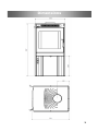
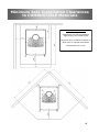
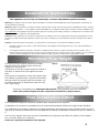
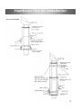
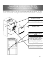
Issued: March 2012 V1.2 Specifications, Installation and Operating Instructions for the FERVA Corsair Solid Fuel Burner USB CORSAIR KEEP THESE INSTRUCTIONS FOR FUTURE REFERENCE Proudly Manufactured By: Harris Home Fires 41 Braddon St Addington Christchurch 8024 New Zealand Email [email protected] P O Box 4043 Christchurch 8140 New Zealand Phone 03 366 1796 Freephone 0800 3661796 Fax 03 366 1795 1 Contents PAGE Testing and Certification 2 Dimensions 3 Clearances & Hearth 4 Installation Instructions 5 Minimum Flue Height 6 Flue Installation Details 6 HeatSaver Flue Kit Installation Instructions 6 Operation Instructions Wood 7&8 Caring for your Fire 9 Consumables 10 Creosote Formation 10 Storage of Fuel 11 Useful Tips 11 TEG Operating Instructions 12 Trouble Shooting 13 & 14 Warranty Details 15 Testing and Certification MODEL Corsair AS/NZS 2918:2001 AS/NZ 2918:2001, APP E AS/NZS 4012:1999 AS/NZS 4013:1999 ECan Cert Number Complies N/A 71% 0.65g/kg 121490 2 Dimensions 3 Minimum Safe Installation Clearances to COMBUSTIBLE Materials Important Information Clearances are with the 900mm high factory flue shield fitted Minimum floor protector material is 8mm tiles or thermal equivalent Dimensions are in mm 4 Installation Instructions This appliance should only be installed by a trained and NZHHA qualified installer. Warning: the appliance and flue system shall be installed in accordance with AS/NZS 2918 and the appropriate requirements of relevant building code/codes. Warning: appliances installed in accordance with this standard shall comply with the requirements of AS/NZS 4013 where required by the regulatory authority, i.e. the appliance shall be identifiable by a compliance plate with the marking “Tested to AS/NZS 4013”. Any modification of the appliance that has not been approved in writing by the testing authority is considered to be in breach of the approval granted for compliance with AS/NZS 4013. Caution: mixing of appliance or flue system components from different sources or modifying the dimensional specification of components may result in hazardous conditions. Where such action is considered, the manufacturer should be consulted in the first instance. Caution: cracked and broken components e.g. glass panels or ceramic tiles, may render the installation unsafe. Maintain a clearance of at least 1 metre between front of the appliance and building structure or any other substantial immovable object. Your appliance shall be seismically restrained, including the floor protector using the provided holes or brackets. The restraints should be sufficient enough to resist a seismic loading equal to 0.4 times the mass of the appliance. We recommend a minimum of 8mm dynabolts on concrete floors and 8mm coach screws for wooden floors of appropriate length. Minimum Flue Height The top of the flue system should be at least 600mm above the highest point of the roof ridgeline, if the point of intersection of the flue system and the roofline is less than 3 metres from the ridgeline horizontally. If the point of intersection of the flue system and the roofline is greater than 3 metres horizontally, the top of the flue system shall be at least 1 metre above the point of intersection with the roofline. (refer FIG 3) These are considered to be minimum dimensions, and depending on local conditions, taller flue system heights may be required for satisfactory performance. Flue Installation Detail Your Woodsman appliance should be installed with a HeatSaver Flue System. A HeatSaver Flue System is available from all authorised Woodsman dealers throughout New Zealand. The HeatSaver Flue System contains a complete installation drawing and correct clearances from the ceiling level up. Minimum clearances from the appliance to nearby combustible surfaces are given in FIGS 1 & 2. Use of a flue system other than a genuine HeatSaver Flue System may affect the safety of the installation, and may affect your warranty. Insist on a genuine HeatSaver Flue System. 5 HeatSaver Flue Kit Installation INSTALLATION INSTRUCTIONS This HeatSaver flue system is tested and certified to AS/NZS 2918:2001 Appendix F, which means it is approved for use on all solid fuel appliances with a flue diameter of 150mm. A copy of the Laboratory Test Certificate for this HeatSaver Flue System is included as part of these Installation Instructions, (refer to paperwork with flue kit). Installation of any solid fuel appliance should only be carried out by suitably trained and qualified personnel. Position the stove to the desired position, always ensuring that the manufacturer’s minimum clearances to combustibles are complied with. Check that there are no roofline ridges or valleys in the way, or if they cannot be avoided, that the installer knows how to weatherproof the penetration and reinstate the full strength of the structure. At the ceiling level, construct a square frame of 300mm x 300mm internal dimensions and cut away the ceiling materials from the inside of this frame. Lower the 300mm flue pipe casing into this frame and nail in place when the bottom edge is 25mm below the ceiling level and the 8 nail holes provided are touching the timber frame. Ensure that the spacer brackets are at the top of the casing as shown in the diagram. Check all 4 locating brackets are securely in place and drop 250mm diameter lower casing in place. This will naturally settle so it protrudes 25mm below the ceiling. Make roof penetration, assemble and fit required flue length and install with upper casing. Secure all joins with at least 3 stainless steel rivets or self tapping screws. Frame and brace upper installation as required and flash the roof to shield penetration. Fit ceiling plate to ceiling. When trimming the stainless steel flue length, remember to allow for expansion when flue is hot. Fix HeatSaver Columbian Cowl in place. Fixings are not required as the cowl clips into place. Secure the flue to the fire—drill through flue neck on fire and secure with 2 to 3 s/s screws or rivets. All flue joints should be sealed using a flue cement. 6 HeatSaver Flue Kit Installation 7 Operating Instructions (Burning Wood) Keep these instructions for future reference Important: ensure installation instructions have been adhered to before lighting the appliance. Important: firewood should be loaded in a front to back direction when operating this appliance. Warning: any modification of the appliance that has not been approved in writing by the testing authority is considered as breaching AS/NZS 4013. Warning: do not use flammable liquids or aerosols to start or rekindle the fire. Warning: do not use flammable liquids or aerosols in the vicinity of this appliance when it is operating. Warning: do not store fuel within heater installation clearances. For your comfort, it is advised that you light your first fire with the windows open to allow the escape of paint fumes. This will normally happen for the first 30 minutes of the first burn. Fully open the heat control. Place wood kindling and paper or firelighter in the firebox. Ignite and leave the door partially open by resting on the catch until the fire is blazing (4-5 minutes), and burns well with the door closed. Do this only from a cold start. Once the fire is underway, adjust the heat control to suit. If the firebox or the flue becomes visible red-hot, adjust the heat control to a lower heat position to avoid being unnecessarily harsh on the unit as well as wasting excessive heat up the flue. Warning: always open the heat control before opening the fire door. For long holding operation in a Clean Air Zone, level the ashes and load with the firewood lying front to back. After loading new wood, operate the fire with the heat control fully open for 20 minutes before closing the heat control to the lower burning position. By following this simple method of low burn firing, you will achieve very low emission rates and obtain the high efficiency burn that is associated with the product. The fuel approved for use in Clean Air Zones in this appliance is wood with a moisture content of less than 25% of dry weight. This usually means green timber left for at least three months to air dry. Caution: the use of some types of preservative-treated wood as a fuel can be hazardous. Caution: this appliance should not be operated with cracked glass. Caution: this appliance should be maintained and operated at all times in accordance with these instructions. The door must be closed at all times during the operation, except during refuelling and occasional poking of the fire when necessary. Ensure door seals are maintained in good condition. Your appliance and flue system should not be modified in any way without the approval of the manufacturer. 8 Caring for your Fire Cleaning your Glass Wiping your glass regularly with a damp cloth when cold will keep the glass clean. If a thick build up of creosote builds up, oven cleaner works well to remove it. Cleaning the Outside of the Fire Ferva fires are finished in a high temperature paint. Only use a damp cloth (no chemicals) when cleaning the outside of the fire. If any scratches occur, you can easily touch up the fire with an aerosol can of matching paint. This is available from your retailer or Harris Home Fires. Cleaning the Flue Keeping your flue clean is important. We recommend that you have your chimney swept at least once a year. A blocked flue not only effects the performance of the fire, but can also be a hazard as you are susceptible to chimney fires. Ash Level It is important to maintain a 2 - 3cm level of ash in the bottom of the fire for insulation purposes. But do not let the level get too high as you run the risk of logs and coals falling out of the fire. You also get less wood in the firebox. Disposal of Ashes Ashes should be placed in a metal container with a tight-fitting lid. The closed container of ashes should be placed on a non-combustible floor or on the ground well away from all combustible materials, pending final disposal once cooled. Consumables Some parts of your Ferva fire are considered consumable. They are designed to be replaced as they will degrade over time. The life of the consumables will vary depending on; Frequency of use. How often the fire is used Rate of burn. Is the fire burning on low or high the majority of time Type of fuel. Some woods and coals are much harsher than others. Level of ash. High levels of ash can push embers up and over rear air tubes General items that are considered consumables: Baffles Fire bricks Air tubes Glass and door ropes It is very important that you replace these parts when they show sign of wear. They effect how the fire runs and you may increase your fuel consumption or lower your efficiency if not replaced, and can in some cases, damage the firebox. It is generally obvious once a part is in need of replacement. Steel components may split or large holes may appear and fire bricks may disintegrate. Fire bricks that are cracked but still remain in place are completely safe to use and only need to be replaced when they no longer remain in place. A cracked fire brick may still last years of use. We recommend you check your fire visually several times a year for damaged components. 9 Creosote Formation A small intense fire is preferable to a large smouldering one, to reduce the amount of creosote. When wood is burned slowly it produces tar and other organic vapours, which combine with expelled vapour to form creosote. These creosote vapours condense in the relatively cool flue of a slow burning fire. As a result, creosote residue accumulates on the flue. When ignited, this creosote makes an extremely hot fire. The flue should be checked at least every 2 months, during the burning season, to determine if a creosote build up has occurred. If this is the case, it should be removed by a chimney sweep to reduce the risk of an unexpected flue fire. Your appliance has been designed to produce low levels of creosote at high and low settings. In the event of a chimney fire, close the firebox door, fully close the heat control, vacate the premises and call the fire service. Storage of Fuel Do not store fuel within installation clearances or within the space required for refuelling or ash removal. Wood should always be stored in a dry place out of the rain. We recommend your wood be seasoned for at least 3 months before use. Dry wood also burns hotter and more efficient than wet wood. 10 Useful Tips Get the most out of your fire Tips for lighting the fire Use finely cut, dry kindling wood. Firelighter cubes or gel work best when ensuring ignition of the kindling. Cross stack kindling over and around fire lighter like a small tower. Use ample kindling wood to ensure a good fire, you want to get the fire hot as fast as you can. Tips to help get the highest heat output: Open the air slide to increase the amount of combustion air to the combustion zone. Use smaller pieces of wood and lots of it. Small pieces of wood have a larger surface area compared the same volume of wood but in larger pieces. Feed the fire regularly. Keep the fire topped up with fresh wood to keep the temperature up in the combustion zone. Use dry wood. Wood with a moisture content of less than 16% will burn much hotter than damp wood. Use a moisture meter to determine the moisture content of the wood. Use a soft wood. Soft woods like Radiata Pine burn fast and hot. Tips for increasing the burn time: Shut down the air slide to decrease the amount of combustion air to the combustion zone. Use large pieces of wood. Large pieces have a smaller surface area compared to small pieces of the same volume and will burn slower. Use a hard wood like Blue Gum (where permitted). Hard woods are denser and take longer to burn. Completely fill the fire box with large pieces of wood. The more wood in the fire, the longer it takes to burn. Load the wood at the right time. If you load the fire when there is a large amount of red embers, the wood will all combust at the same time. A good idea is to let the fire burn down quite considerably and push the embers off to one side. Stack the wood in the firebox and the wood will ignite on one side only and slowly burn from one side to the other. 11 Operating Instructions for the Thermoelectric Generator (TEG) Your TEG is designed to automatically turn on when the fire is in use and will automatically turn off once the fire has cooled down. There is no on/off switch. The fan has 2 settings. (I) Low or quiet setting (II) High setting. Adjust the fan speed to suit your needs. The high setting should be used to distribute the heat quicker and the low setting to be used once the room is up to temperature or you desire the quiet setting. The LED light indicates when the unit is generating power. When you light the fire, it will take approximately 20 minutes until the fan is operational. The LED light will come on some time before the fan has started. The fan may run for some time after the fire has gone out. Your TEG does not require any maintenance, but the fire will require normal maintenance as illustrated in this manual. The USB socket can be used to charge cell phones and other portable USB devices. It supplies 5VDC @500mA. Only connect one device at a time. IMPORTANT It is very important that the 2 rear fire bricks remain in place. If removed, the TEG may be damaged from overheating. Cracks in the rear bricks are totally acceptable as long as they remain in place. If your rear bricks are severely damaged and can no longer remain in place, they should be replaced before using the fire. Because the TEG is a low voltage system, there is no risk of electrocution from the appliance. DC devices are considered very safe. 12 Operating Instructions for the Thermoelectric Generator (TEG) In the event of a failure of the TEG, the LED light and/or fan will not run. The TEG should be replaced by following the below instructions before the fire is used again. 1. Remove side panels by pulling the top out of the clips 2. Remove rear panel by pulling out the of the clips 3. Remove back section of the duct by undoing screws 4. Unscrew control box from the side once side panel has been removed. 5. Remove the top and bottom fire bricks followed by the rear air tube. The rear airtube is held in by 2 pins, remove and slide out. Once removed, this exposes 3 hex nuts. Undo these and the TEG will be released 6. The TEG is now released, replace entire unit including the control box. Reverse these steps. 13 Trouble Shooting My fire won’t turn down The first thing to be aware of is that some new clean air fires do not shut down like old fires. Old fires used to shut all the way off and the wood would just smolder. Other reasons for this problem may be: Rear air tube has burned out and needs replacing, visually check. Door seal is not sealing properly and may need replacing. Take a thin strip of news pa per, close the door on it at various spots, if the paper can be easily pulled out, then either a new door rope is needed or door latch needs adjusting by redistributing the washers on the door latch. There is rust on my fire Rust appearing on your fire can only occur when moisture or water is present and has began to oxidize the steel. Identify where the water or moisture has come from and fix the problem. Lightly sand the effected area and use matching FERVA aerosol high temperature paint to touch up. My glass is dirty Your glass can get dirty easily if you use poor quality or wet wood or spend a lot of time with the fire on the low setting. Give the fire a good hot run on the high setting to burn off the residue on the door If that fails, there are special cleaners especially for this purpose or oven cleaner works well. Do not get chemicals on the paint work. My fire smokes when I open the door There are many reasons which may cause this symptom and it is often a process of elimination to remedy the problem. Your flue length may be too short. Even though it may be of legal length, every installation is different and you may require an additional length of flue. Your flue may be blocked, have the flue looked at. The baffle may not be in place correctly, visually check to see if it has moved. You may need a cowl like the Columbia cowl to help encourage draw, especially where there are environmental problems like high winds. Your flue may be getting too cold. If the flue gases get too cold, they can struggle to be exhausted and when the door is opened, they find it easier to exit via the door than the flue. If you suspect your flue is getting cool, turn the fire up onto high for a few minutes before reloading, this will increase the temperature of the flue and increase the flue draught. Check that the installer has sealed ALL the flue joints and there are no gaps which will leak air into the flue, reducing the draw. The paint has been damaged Paint finishes are not as durable as enameled finishes, but they are extremely quick and easy to touch up and the fire can look new in minutes. If damage has occurred to the paint, lightly sand the effected area and touch up using Ferva High Temperature Paint. My fire seems to be performing poorly, not burning well on high If your fire doesn’t seem to burn well at the high level, check the following: Negative pressure, make sure there are no extraction devices like fans creating a negative pressure in the home. The flue length is long enough. The wood is dry. The flue is clean. 14 10 Year Firebox Warranty 1 Year Parts Warranty Your FERVA fire is warranted for a period of 1 year to the original purchaser, from the date of purchase, against defective materials and workmanship which includes the firebox and all parts. If a part defect occurs, return the part to the retailer or directly to Harris Home Fires along with a copy of the retailers receipt and the part will be replaced at no cost. If a firebox defect occurs, either contact the retailer or Harris Home Fires and it will be repaired or replaced at our discretion with all costs covered. This warranty does not cover damage caused by mishandling, misuse, failure to follow the manufacturer’s installation and operating instructions, or work done by others, such as installers, or plumbers etc. The manufacturer shall not be responsible for site conditions such as insufficient draught, downdraughts, or routine servicing and adjustments. Damage caused by the failure to replace consumables like air tubes, baffles and fire bricks may void the warranty. Your FERVA firebox is then covered by a further 9 year warranty against defective materials and workmanship during normal domestic use. In the case of a claim after the first year, this warranty covers the replacement or repair at the manufacturer’s discretion and includes freight, painting and all required refurbishment but does not cover the cost of having the appliance disconnected and reconnected. It shall be the owner’s responsibility to have the fire available and ready for pickup from onsite or another suitable location or deliver the fire to either the dealer from whom it was purchased or directly to Harris Home Fires. Your Thermo-Electric Generator (TEG) is covered by a 1 year warranty which includes labour. In the event of a failure after the first year you may purchase a replacement TEG or may send the unit back to HHF for refurbishment. It may be that only a minor part needs replacing which will significantly reduce the cost. Harris Home Fires 41 Braddon St Addington Christchurch 8024 New Zealand Email [email protected] P O Box 4043 Christchurch 8140 New Zealand Phone 03 366 1796 Freephone 0800 3661796 Fax 03 366 1795 15