1
OPEN LOOP - WELL WATER SYSTEMS
Water Quality
Water Control Valve
Water quality should be plentiful and of good quality.
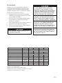
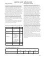
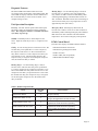
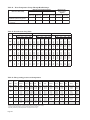
Table 4 shows recommended water quality guidelines.
The unit can be ordered with either a copper or cupronickel water heat exchanger. Copper is recommended for
closed loop systems and open loop ground water systems
that are not high in mineral content or corrosiveness.
In conditions anticipating heavy scale formation or
in brackish water, a cupro-nickel heat exchanger is
recommended. In ground water situations where scaling
could be heavy or where biological growth such as
iron bacteria will be present, a closed loop system is
recommended. Heat exchanger coils may over time
lose heat exchange capabilities due to a build up of
mineral deposits inside. These can be cleaned only by a
qualified service mechanic as acid and special pumping
equipment are required. Note: Desuperheater coils can
likewise become scaled and possibly plugged. In areas
with extremely hard water, the home owner should
be informed that the heat exchanger may require
occasional acid flushing.
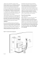
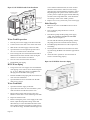
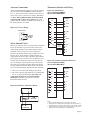
Note the placement of the water control valve. Always
maintain water pressure in the heat exchanger by placing
water control valves at the outlet of the unit to prevent
mineral precipitation. Pilot operated or slow closing
valveʼs solenoid valves are recommended to reduce water
hammer. If water hammer persists, a mini-expansion tank
can be mounted on the piping to help absorb the excess
hammer shock. Insure that the total "VA" draw of the
valve can be supplied by the unit transformer. For instance
the slow closing valve can draw up to 35VA. This can
overload smaller 40 or 50 VA transformers depending
on the other controls employed. A typical pilot operated
solenoid valve draws approximately 15VA. Note the
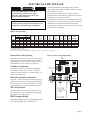
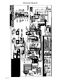
wiring diagram in Figure 20.
Expansion Tank
Use a closed, bladder-type expansion tank to minimize
mineral formation due to air exposure. The expansion
tank should be sized to handle at least one minute run
time of the pump to prevent premature pump failure using
its drawdown capacity rating. The pump should be sized
to the homeʼs domestic water load (5-9 gpm) plus the
heat pump water load. Discharge water from the unit is
not contaminated in any manner and can be disposed of
in various ways, depending on local building codes, i.e.
recharge well, storm sewer, drain field, adjacent stream
or pond, etc. Most local codes forbid the use of sanitary
sewer for disposal. Consult your local building and zoning
department to assure compliance in your area.
Flow Regulation
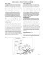
Flow regulation can be accomplished by two methods.
Most water control valves have a flow adjustment built
in. By measuring the pressure drop through the unit heat
exchanger flow rate can be determined and compared
to Table 9. Since the pressure is constantly varying two
pressure gauges might be needed. Simply adjust the
water control valve until the desired flow of 1.5 to 2 gpm
per ton is achieved. Secondly a flow control device may
be installed. The devices are typically an orifice that is
designed to allow a specified flow rate. These are mounted
on the outlet of the water control valve. On occasion these
valves can produce a velocity noise that can be reduced
by applying some back pressure. This is accomplished
by slightly closing the leaving isolation valve of the well
water setup.
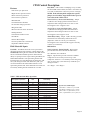
Freeze Protection Setting
CXM or DXM Control:
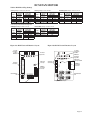
When well water is used, the FP1 jumper (JW3) should be
NOT be clipped, but should be left in the factory position
of water setting (30°F). See Freeze Protection Selection.
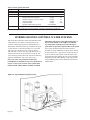
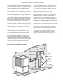
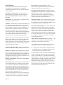
Figure 11. Typical Well Water/Open Loop System
Page 9