1
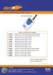
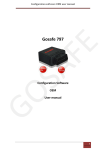
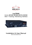
Alert-it Care Systems
P135 Personal Alarm
Alarm Badge
User Handbook
P135AB
P135AA
Models covered by this handbook
Long range personal monitor badge
Short range personal monitor badge
One of a range of Alert-it Care
Alarms available from:
This handbook is intended to assist carers install, configure and use the monitors.
The carere therefore needs to understand the needs of the user and asses that the
monitor meets those needs and if any supplementary monitoring is needed taking
into account any health risks.
The P135A is a miniature badge style monitor that is capable of sending alarms to
the P137/P138 Safelink Pagers or P117C Telephone Autodialler, and is especially
suited to those living alone or in a supported environment. It can also be coupled to
established Nurse Call systems via our P155 Radio Alarm Receiver.
Typical range outdoors is 100m for P135A or 450m for the P135B
The alarm can be programmed to detect
1. User pressing the front call button
2. User falling to an angle of 60º or less (even if they continue to have seizre
activity)
3. User risking hypothermia (special programmed option)
4. User wandering too far from pager (see pager programming manual)
Power for P135
The badge is powered by a replaceable lithium button cell battery which should last
more than a year in fall mode (&2) or 4 weeks modes 3 or 4. A spare battery is
included with the unit. A card of 5 batteries is available from iTs Designs Ltd
(order code P160)
To prevent the fall alarm activating in the post, the P135 is shipped in a deactivated state. The HELP button must be pressed until a beep is heard to activate
the unit for the first time. (The same procedure is needed after battery replacement)
UH1101A P135 User Handbook page 2 of 8
Typical System Configurations
The P135 Badge uses radio to transmit
an alarm when a fall is detected or the
panic button is pressed
Optionally the P135 can make a regular
transmission which is used by the P137/8 pagers
to prove the integrity f the radio network and can
be used to detect wandering outside a safe area.
The regular transmissions will reduce battery life
The P137/8 pagers will give
full details of battery and
alarm status. It can also use
the regular Safelink
transmission to warn of
wandering or radio failure
The P155B Radio Receiver can connect
to a Nurse Call system or an autodialler
(as shown).
The receiver shows successful radio
reception by the flash of a green light.
It will warn of radio failure when the
Securelink protocol is enabled by a red
light and audible alert
UH1101A P135 User Handbook page 3 of 8
Installation
Fall Detection:
The unit should be clipped to clothing using the rear clothing clip or pin, in a
position that best fits the anticipated fall condition.
Clipping to the waist band is an excellent place that is unobtrusive and capable of
detecting a full fall with few false alarms.
For those prone to slumping while seated then clipping to the upper torso is
recommended. This also gives easier access to the panic button.
In situations where a drop will not occur (eg watching Tv in an armchair) the user
is advised to hold the badge and throw it or drop it when a seizure starts
It is also possible to stand the unit up on a nearby coffee table and kick/knock it
over when a seizure starts
False alarms will be caused if the user lies down to rest while wearing the badge
Panic Only
The badge can be supplied to special order without the fall detection., to act as a
simple panic badge (with the potential of hypothermia or wandering detection).
This version can be fitted with a lanyard.
Wandering Detection
For this to work the unit must be set into Securelink mode (see page 8). This makes
the badge transmit are radio signal every 10 seconds which can be used to check
approximately how close the badge is to the pager. The battery life will be reduced
in this mode.
The pager is first put into “learn” mode where by the weakest radio signal strength
is recorded while the badge is carried around the care home. The transmissions can
be forced to occur faster by pressing the HELP badge quickly (less than 1 second to
save setting the alarm). This should be done at all the recognised extremities.
The recorded values are then saved as the wander detection value and the pager returned to normal use. If the radio strength falls below this saved value then a
WANDER alarm is indicated. This automatically cancels once the badge is back
within the limits.
The method of detection is not a precise concept (as GPS) and
some level of false alarms may occur. However it is cost effective, convenient system and unlike GPS based systems it will
work quickly when the user exits a building.
If the user escapes out of range completely, then the RF Fail warning will appear
after 2 minutes as a further level of protection.
The detection value can be adjusted manually on the pager if false alarms occur.
For information about pager programming see the P137 Programming Handbook.
UH1101A P135 User Handbook page 4 of 8
Installation (cont)
Hypothermia Detection
This version uses an internal temperature sensor to guage the ambient temperature
around the client. An alarm will be raise if this temperature falls below 12°C for
more than 1 hour. These parameters can be adjusted to order.
Range test.
If the unit has the failsafe feature enabled, then the pager will automatically warn if
the regular radio transmission is lost. If this is not the case then the badge should be
tested in all the usual locations to prove signal reception. A short press on the
HELP button (less than 1sec) will cause the P135 to transmit, without setting an
alarm
In large installations a more convenient method is to have one P135 with the failsafe capability enabled (see below). This is then positioned where the pager would
normally be situated and the pager taken around the whole area to be monitored.
Any loss of signal is then apparent when the pager fails to show reception of the
test badge signal (when the “name” stops flashing onto the display every 10 seconds)
UH1101A P135 User Handbook page 5 of 8
Operation
Regular Battery Test
In the non-failsafe mode the battery will last up to a year, but should be checked
regularly by making a short press of the Panic Button (less than 1 second so that no
beep sounds). If the battery is serviceable than the light will flash. The P135 will
also transmit at this time. In Securelink mode the battery status is being monitored
continually.
If FAULT 30 or 31 shows on the P137/8 pager, or the P117 autodialler gives an
intermittent audible alarm and activates the fault alarm message, then the battery
will need replacing. The P135 will continue to function for some hours (but with a
slow flash of the light every 8 seconds), allowing time for this replacement. If the
battery is exhausted then the P135 will chirp continuously without the light flashing
or transmitting.
In a fall
When the P135 is made horizontal then after 15 seconds an audible pre-warning
will start and the red light will flash. The initial, silent delay prevents false alarms
during normal movements.
The pre-warning tone decreases in pitch over 30 seconds (to assist those with
impaired hearing). If the user does not return to the upright position during this
period, then the tone stops and the full alarm is transmitted. The red light continues
to flash to indicate the latched alarm
Use of HELP button
Pressing the panic button for 1 second will produce a short beep and
an ASSIST alarm will be sent immediately. The red light will then
flash to indicate the latched alarm status.
Clearing the alarm
If the panic button is pressed for 1 second, while any alarm
is active (the red light flashing), then, after a short beep, the
alarm will be cleared. This is noted by the light
extinguishing
UH1101A P135 User Handbook page 6 of 8
Operation (cont)
Turning off the Badge
The badge contains a small magnetically operated
switch which can be used to turn off the badge, for instance at night. The magnet is passed over the front of
the unit, and the alarm light is noted to blink.
The unit is turned back on by pressing the HELP button until there is a beep heard.
Alarm indication at the pager/receiver
Alarm
Detect Delay
Pre-warn
P135
Pager
P155 /P117C
Panic
1 second
No
Flash
Assist 01
Intermittent tune + alarm
Fall
30 sec
15 sec
Flash
Urgent 01
Continuous tune + alarm
Hypother- 1hour
mia
No
Flash
Urgent 02
Continuous tune + alarm
Wander
10 sec
No
No
Wander
Intermittent tune + alarm
Escape
2 min
No
No
RF Fail
Intermittent tune + alarm
TEST
Less than 1 sec
No
Flash
Node Name
Green light flash
Battery
Low
-
-
Flash every
8 sec
Fault 30
Intermittent tune, + alarm
Battery
Fail
-
-
Flash every
8 sec
Fault 31
Intermittent tune, + alarm
Battery
Dead
The P135 chirps every 0.5 sec with no LED and no transmission
UH1101A P135 User Handbook page 7 of 8
Maintenance
Cleaning
The badge is IP61
rated and capable of
being cleaned to
Alert-iT Method
Technique B
Technique B
Wiping with cotton wool pads moistened (compressed
until dripping stops) with a mild detergent (0.5% washing up liquid) solution.
Battery Replacement (see diag page 10 )
The anticipated battery life is shown below
Operating Mode
Battery capacity
No failsafe heartbeat, no alarms
1 year
Using failsafe heartbeat, no alarms
1 month
Maximum alarm number 1
2000 alarms
1
Based on fall alarms with 2 minute response time from carer
Failsafe Operation
An internal link selects failsafe Securelink mode
Remove the link for maximum battery life, but note the warnings that
alarms may be missed if the radio path is interrupted or the badge fails.
Add the link to create the highest integrity systems.
To change the link, open the case and remove the battery as described on page 10
and fit the link as shown below to enable Securelink. To remove Securelink simply
Link enables“Securelink” operation. If not
required then remove for maximum battery
life
Programming and enabling failsafe operation
UH1101A P135 User Handbook page 8 of 8
Maintenance
remove the link and store by fitting to one pin only. Refit the battery. This is an
essential step as the link is activated when the battery is enabled.
Close the case and enable the battery by pressing nthe HELP button until a beep
is heard
Configuration Changes
The P135 uses the standard Alert-iT Programming Data Protocol and all the
main features can be changed using the P152 USB Interface and Data Editor
Programme.
Communication Address Changes
Each badge in a care home MUST have a different communication address. To
facilitate easy installation the Communication Address can also be changed directly from the pager using the P173A programming cable
UH1101A P135 User Handbook page 9 of 8
Maintenance (cont)
Open the case carefully buy pulling apart without
twisting, after unscrewing the one rear fixing screw
Aerial coil
In all the following procedure be careful not
to damage the aerial coil
Use a small screwdriver , match, cocktail
stick or similar implement to start the
ejection of the battery from its holder. Then pull
clear of the housing
Remove and then replace the
battery (note the + side is
upwards).
Battery Type: 3v Lithium Coin Cell CR2025 or equivalent
(order code P160 for 5 batteries)
Reassemble the case.
The P135 must now be activated by pressing the red button for 1 second until
a beep is heard
UH1101A P135 User Handbook page 10 of 8
Safety Instructions and Warnings
!
This symbol indicates there are warnings and precautions associated with the use of this
equipment that should be carefully read and understood before using the equipment.
1.
2.
3.
4.
5.
Clean and disinfect each item regularly in accordance with information herein
Regularly test as described herein
Ensure, by testing, that the alarm is annunciated at the carer's location(s)
Charge pager away from direct heat and uncovered.
As with all medical electronic equipment there is potential for the equipment to interfere with or be effected by interference from other electrical or electronic devices. For
this reason avoid placing the monitor, sensor or connecting cable in close proximity to
sensitive electronic devices or devices which produce strong electromagnetic fields
such as radio transmitters, mobile phones or power cables.
6. If the equipment is modified in any way, appropriate inspection and testing must be
conducted to ensure continued safe use of the equipment.
7. The carer must conduct a risk assessment to determine if the level of reliability offered
by the monitor is sufficient or if additional monitoring is needed. Contact the manufacture for assistance with Risk Evaluation Tools.
8. Ensure the badge and any associated parts do not come into the possession of vulnerable patients who might choke on them
9. The monitor and all accessories are designed to operate indoors in a residential environment of 10ºC to 30ºC and 90%RH max.
10. The fall detection requires the user to lie in a semi prone position. Some falls may not
achieve this and hence if the user is at high risk in a fall, there should be frequent observations made on their well being
The Alert-it system has been designed with due regard to reliability and integrity. While it offers a highly
vigilant monitoring method,it is always possible that a distress condition can go undetected for a variety
of reasons (including malfunction) and in life threatening situations it is advisable to use the Alert-it
system in conjunction with additional monitoring techniques (e.g. video). Neither the manufacturer nor
its agent can accept legal responsibility to provide a system that is infallible. The carer is responsible for
assessing the risks of using this equipment and any settings pertaining to it.
UH1101A P135 User Handbook page 11 of 8
This system is certified to the following European Standards
Class 1 Medical Device
Permitted radio transmission
Risk Assessment
Safety
Assistive Technology
EMC
93/42/EEC: 2007/47/EC1
EN 300 220-1 V2.1.1 (2006-04)
EN 14971:2007
EN 61010-1:2005
EN12182:1999
EN 61010-1-2:2004
Also complies with
2002/95/ECRoHS
Permitted Materials
1Alert-it
Care Alarms are social aids designed and manufactured in accordance with
93/42/EEC as Class 1 Medical Devices. They are intended to improve the vigilance of carers
to distressing side-effects of various diseases, such as Epilepsy and Dementia. They do not
monitor vital physiological processes and should not be expected to diagnose any disease or
predict the onset of any symptoms.
Additional Documents
Quick Start P135 with Pager
UQ1131
Quick Start P135 with Autodialler
UQ1130
P137 Configuration Handbook
UH1068C
You tube Instruction Videos Index
UV1198
Support
For technical support please fax or EMail:
HELP: 0845 2179951
FAX : 0845 2179953
[email protected]
Designed by:
ITs Designs Ltd
Leicester
LE9 9FE UK
...using technology to care for carers
UH1101A P135 User Handbook page 12 of 8