1
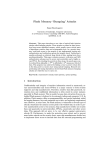
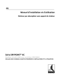
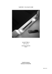
DRYPOINT AC
®
Instruction & Technical Manual
BEKO TECHNOLOGIES GMBH Im Taubental 7 D-41468 Neuss
Tel. +49 / (0) 21 31 / 988-0 Fax. +49 / (0) 21 31 / 988-900 [email protected]
Table of Contents
Page:
1. Introduction ...................................................................................................................................................................... 3
2. Safety....................................................................................................................................................................................... 4
3. Description of the dryer’s main components................................................................................. 6
4. Explanation of the dryer’s main components ............................................................................... 7
5. Connecting the pre-filter to the dryer ................................................................................................... 8
5.2 Reconfiguration of the inlet and outlet ports............................................................................ 9
5.3 Installing the dryer in a horizontal orientation ..................................................................... 10
6. Installation ...................................................................................................................................................................... 11
7. Electrical supply......................................................................................................................................................... 12
8. Energy management and PC interfacing ......................................................................................... 14
9. Operation ......................................................................................................................................................................... 24
10. Start up ........................................................................................................................................................................... 25
11. Service and fault diagnosis......................................................................................................................... 26
12. Dryer troubleshooting ..................................................................................................................................... 35
13. Dryer sizing table .................................................................................................................................................. 37
14. Environmental conditions ............................................................................................................................ 38
15. EC Declaration of conformity ................................................................................................................... 39
2 | BEKO TECHNOLOGIES GMBH
1. Introduction
The product to which this manual refers must not be supplied, installed, used, operated
or serviced until the contents of the manual have been fully read and understood by all
relevant personnel.
This manual, and in particular the safety information, should be kept at the place of
installation of the product. All relevant personnel must strictly follow instructions given
in the manual.
When contacting BEKO regarding this product or manual, please have the following
information available:
•
Serial number:
•
Date of commissioning:
The serial number can be found on the identification plate located at the upper right
hand side of the unit and this information should be copied into this manual for future
use.
The dryer is delivered in protective packaging. Take care when transporting, loading and
unloading the unit.
The dryer is delivered configured for operation at the pressure mentioned in your order.
It is important to ensure that the correct plug is fitted applicable to the operating
pressure. See table on page 38 for further information.
The dryer package includes:
Instruction & Technical Manual | 3
2. Safety
BEKO explicitly excludes all responsibility and liability for damage and/or injury caused by
failure to follow the instructions described in this manual, or by failing to pay necessary
attention when operating handling or servicing this product, even if not specifically
stated in individual cases.
The unit must be used for its intended purpose. The heatless-regenerating adsorption
dryer is designed and manufactured exclusively for drying of compressed air within
conditions as described in section 13 of this manual. Any other use of the unit will be
considered inappropriate and BEKO shall not be liable, where this is permitted under
law, for any damage incurred as a result of misuse.
The following symbols give indication of potential hazard. Appropriate measures must
be taken to reduce risk to any user or operator of the machine wherever such hazard
exists.
Warning:
Caution:
Caution:
Risk of Danger
Risk of High Pressure
Risk of Electric Shock
4 | BEKO TECHNOLOGIES GMBH
The following safety guidelines must be strictly observed:
• Leave this manual at the place of installation of the product.
• It is essential that only BEKO or their appointed agents carry out maintenance and
servicing work.
• Users, maintenance and servicing personnel must be familiar with:
• accident prevention regulations
• safety information (general and specific to the unit)
• safety devices of the unit
• measures to be taken in case of emergency
• Allow only suitably trained persons to be involved with installation, start-up,
operation, servicing and maintenance of the product.
• It is the responsibility of the installer to ensure that the pipe work to and from the
dryer is suitable, in accordance with applicable legislation and subject to inspection
and testing prior to being put into service. All piping must be adequately supported.
• Before carrying out any maintenance or servicing work the unit must be taken out of
operation. Users and others will be exposed to risk if work is carried out whilst the
unit is running. This means electrical disconnection plus isolation from the
compressed air supply and full depressurisation.
• Only trained and competent persons familiar with the electrical requirements of the
unit as laid out in this manual and electrical safety rules and regulations
should be allowed to carry out work on the electrical components and power supply
to the unit.
• When carrying out any work on the unit, use only correctly sized appropriate tools in
good condition.
• Only use original spare parts and accessories from the manufacturer. There is no
guarantee that non-original parts have been designed and manufactured to meeting
the safety and operational requirements of the unit. BEKO assume no liability for any
equipment malfunction resulting from the use of non-approved parts.
• If carrying out installation work above head height, use suitable and safe working
platforms or other means of working access.
• Do not make any constructional changes to the product. Any changes or
modifications may only be carried out by the manufacturer.
• Any faults or defects that could affect safety must be put right fully before using the
unit.
• Used items and materials must be disposed of in the correct manner, complying with
local laws and regulations, in particular the desiccant cartridge.
Instruction & Technical Manual | 5
3. Description of the dryer’s main components
The figure below shows the main elements of a typical dryer unit.
15
16
12
11
17
13
19
14
Located on rear
panel of dryer
1
9
2
8
10
3
18
6
7
5
4
1
Top valve assembly
10
Desiccant cartridge c/w dust filter
2
Control unit
11
Multiport manifold
3
Bottom valve assembly
12
Top cover
4
Bottom mounting block
13
Top cover fixing screw
5
Bottom valve fixing bolt
14
Rear panel
6
Front panel
15
DIN connector
7
Front panel fixing screw
16
Banjo fixing bolt
8
Pressure housing
17
Pressure seal
9
Pressure housing retaining bolt
18
Exhaust silencer
19
Purge plug
6 | BEKO TECHNOLOGIES GMBH
4. Explanation of the dryer’s main components
4.1 Control unit, item ref. 2 on page 6
The top and bottom valve blocks are operated by solenoids within the control unit that
determine the pressure and direction of air flow into the desiccant cartridges.
4.2 Multiport manifold, item ref. 11 on page 6
The dryer is supplied as standard with inlet and outlet ports configured left to right as
viewed from the front of the unit. There are several optional porting arrangements
available by repositioning of port plugs. See also Section 5.2.
4.3 Desiccant cartridge c/w dust filter
The cartridges contain the agent (desiccant) that has been developed for the drying of
compressed air. The desiccant is housed in a clear tube that has a holder permeable to
air at both ends. Located in the top of each cartridge is a 1-micron filter for removal of
residual dust from the desiccant. The length of the cartridge varies with the flow
capacity of the dryer.
4.4 Pressure housing
The cartridges are contained within an extruded aluminium pressure housing and
pressure retaining end plates. Process pressure and flow through each desiccant
cartridge is controlled by means of top and bottom valve blocks located between the
two pressure housings. The regenerating air flow (purge) is controlled by means of a
small orifice plug located externally (front, central) on the top valve block and is
accessible with the front panel removed.
Instruction & Technical Manual | 7
5. Connecting the pre-filter to the dryer
1. Connect filter and DRYPOINT AC using proper sealing material and the fittings
supplied.
2. If you are using the integrated
condensate drain: Connect condensate
outlet of filet with the condensate inlet
on the back side of the dryer, using the
tube supplied (4mm) diameter. Apply
another discharge tube from the
condensate outlet on the back side of
the dryer into an oil water separator.
If you are using a BEKOMAT 20FM
condensate drain: Apply a discharge tube
from the condensate drain outlet of the
BEKOMAT 20FM into an oil water
separator.
All tubing should be secured up to the point
of drain to prevent whipping during discharge.
5.1 Recommendation
It is recommended that a bypass line including filter (not supplied) is installed.
C
A
D
B
Figure 5.1
8 | BEKO TECHNOLOGIES GMBH
5.2 Reconfiguration of inlet and outlet ports
OUTLETS
INLETS
1. Port configuration as delivered: 3 inlet
options left hand side of dryer as viewed
from front.
5. Dryer with multiport manifold
removed.
2. Remove top cover by means of 2
fixing screws
6. Rotate multiport manifold through 180º
and replace by means of 4 fixing bolts. Ensure
2 ‘0’ rings in valve block are properly seated.
3. Dryer with top cover removed.
7. Replace top cover by means of 2 fixing
screws.
INLETS
OUTLETS
4. Remove multiport manifold by means
of 4 fixing bolts.
8. Port configuration following procedure
above.
Instruction & Technical Manual | 9
5.3 Installing the dryer in a horizontal orientation
1. Inlet filter is fitted to dryer in
vertical orientation. Loosen fitting.
2. Turn filter by 90º
3. Inlet filter is fitted to dryer in
vertical orientation. Tighten fitting.
4. Dryer in horizontal plane.
Consideration must be given to
supporting and to clearance for
removal of inlet filter bowl.
10 | BEKO TECHNOLOGIES GMBH
6. Installation requirements
Correct
Wrong
< 35°C
> 35°C
< 16 barg
< 4 barg
> 12 V
< 12 V
Correct
Wrong
Instruction & Technical Manual | 11
7. Electrical supply
7.1 Connection
1. The dryer is designed to operate on either an AC or DC supply voltage.
Ensure only one power source is connected at any one time, and it is connected to
the correct socket. Cover supplied must be fitted to the power connection not in use.
2. The power supply is to the DIN plug.
No connection must be made
to earth terminal
3. The dryer is double insulated
therefore no earth is required.
4. Suitable external fuse connection
must be provided.
Figure 6.1
5. The cable selection must suit
local installation regulations and
be appropriate to power consumption.
Supply
Amp
12 VDC
0.8
24 VDC
0.4
100 VAC
0.16
115 VAC
0.14
230 VAC
0.07
240 VAC
0.067
12 | BEKO TECHNOLOGIES GMBH
7.2 DIN plug drawings
Voltages: 100 to 240 VAC
cover
Voltages: 12 to 24 VDC
cover
Instruction & Technical Manual | 13
8. Energy management and PC interfacing
8.1 Interfacing the controller with a PC
8.1.1 Introduction to the software
The dryer controller has the ability to interface
with a PC. This gives the user or the service
engineer the opportunity to interrogate the
dryer to check the following:
• Operating stage times
• Service warnings
• Operating history
• Alarm settings
• Fault history
• Fault and service history
• Real Time displays
• Setting Energy Management Parameters –
contact BEKO for details
Connecting the PC to the controller
8.1.2 PC requirements
Controller Application software: Windows 95, Windows 98,Windows 2000, Windows
ME & Windows XP.
8.1.3 Installing the application software
Simply load the CD into the PC and the software will automatically load-up and
complete installation.
The BEKO icon will be visible on the desktop.
8.1.4 Connecting the PC to the controller
Ensure that power to controller is isolated
Access to the controller is by removing the screw on the front panel, and removing the
panel.
Using the lead supplied connect the serial port connector to the PC.
The RS232 connector is located on the underside of the controller.
Remove the blanking plug taking care not to lose it and connect the RS232 connector
with the latch to the front of the dryer.
14 | BEKO TECHNOLOGIES GMBH
1
Controller shown in the inverted
position for reasons of clarity
2
3
1. Condensate solenoid valve
8
2. Tower 1 solenoid pilot valve
7
3. Tower 2 solenoid pilot valve
4. AC&DC supply DIN connections
5. Energy management DIN
connection
4
6
6. Controller clear LED cover
7. RS232 Software connection
5
8. Alarm DIN connection
Instruction & Technical Manual | 15
8.1.5 Starting the program
If not already connected, connect the RS232 serial link cable between the controller and
the host PC.
Switch the power to the controller on. Launch the dryer application software by either
double clicking the Walker Filtration icon found on the PC desktop or by clicking:
Start > Programs > Walker Filtration > Dryer Application Software
The first time the software is used the
following window will appear.
Choose your preferred language by
clicking the appropriate flag.
With the power to the dryer switched
on the lead connecting the controller to
the PC, double click the Walker
Filtration icon on the screen.
This will display the screen below, if the language is not as you require it then click the
appropriate national flag and the next time the application software starts the language
will be in the requested language.
1. Establish communication
Click the “Establish Communication”
switch on the screen this will look for
the link between the PC and the dryer
controller.
6
11
12
2
3
The serial number on the software
must match the serial number on the
controller to allow communications to
be established.
9
1
7
10
4
13
5
8
If communication cannot be made, a
warning will appear at the bottom of
the screen.
This may be due to the following:
• Poor connections to the controller
• Controller switched off
• Application software/controller serial number mismatch
Once communication has been established, click the “Read dryer” button on the screen
this will then display the default setting from the works or the last setting the Service
Engineer made.
It is possible to change some of the controller settings from the factory default settings
on the screen. This should only be done by a qualified service engineer.
16 | BEKO TECHNOLOGIES GMBH
8.1.6 Programming dryer
Once it has been decided to change the default settings, and communications have
been established and the dryer existing valves read the procedure for change is:
• Click into the box you wish to change.
• Over write with the items you require (note stage times are in 10 second intervals).
• Click “Program dryer” ( a warning will appear asking to confirm the change).
• Click to confirm and this will change operating parameter.
• Click in real time to check set up.
2. Read dryer
Reads the current settings of the controller
3. Program dryer
Programs the controller with the new settings
4. Real Time view
This screen can be opened by clicking the real time screen. In addition to the main
display panel shown previously there is also a real time view, which illustrates the
operation of the dryer valves as it happens. It also counts down the remaining time to
run on the valve operation. This is useful in confirming faults, which are displayed with
the LED’s on the front display panel.
To view the status of the controller in real time, click the ‘real time’ view switch. A new
window will appear animating the dryer controller status in real time.
The following information is shown:
• The stage the controller is in through its cycle, including remaining time on the
particular stage.
• Valve conditions
• Power condition
• Cartridge and valve service conditions
• Energy management condition
• Alarm condition
5. Load settings
Allow previously stored settings to be loaded into the controller
6. Stage times
• Tower 1 & Tower 2 – Indicates the time that a tower is depressurised.
• Re-pressurization – Indicates the re-pressurization time set on the controller.
• Link – Enables or disables the tower 1 & tower 2 settings to be linked.
Instruction & Technical Manual | 17
7. Drain valve
• Operate drain operation toggle - Allows the drain to operation to be toggled to
function after both towers or only one tower.
• Operate operation time- Sets the drain operation time.
8. Alarm settings
Allows the service Engineer to toggle and adjust the remote alarm activation values from
the default values.
9. Energy management
Allows the user to set application parameters to save energy during periods of low
demand.
10. Service information
Indicates the default settings at which the cartridge and valve service indicators will
illuminate. The service history of the machine is logged, giving total hours run and hours
run since the last service. Service re-sets provides an alternative method of resetting
service hours than using the re-set disc after a service has been carried out.
11. Address
Indicates the network address for networked dryers.
12. Faults
The first column indicates the number of faults up to 50 every 30 minutes. The second
column indicates the type of fault and the hour it occurred from new.
13. Serial number
Indicates software & dryer serial number to ensure they correspond.
8.1.7 Remote fault alarm
A remote alarm relay is built into the controller to facilitate an alarm connection remote
from the dryer. This can activate at the service due period or with a pre-defined number
of electrical faults or both.
This can be enabled or disabled using the software interface. The alarm requires a power
source to be brought to the controller and on activation the controller will switch on in
an alarm condition. This in turn can be used to activate a remote audible or visual
indicator.
18 | BEKO TECHNOLOGIES GMBH
8.2 Energy management feature (EM)
8.2.1 Description
The purpose of the energy management feature is to save energy by reducing
compressed air consumption during periods of low demand by interrupting the normal
purge cycle. This can be activated with a link from the receiver upper and lower pressure
switches normally fitted to receivers.
In the case where the compressor is a continually running type or the dryer is remote
from the receiver then a dew point dependent switch can be used to activate the energy
management feature.
8.2.2 Energy management connection
1. Remove DIN plug cap from EM
connection on controller.
2. Remove fixing screw and gasket from
DIN plug body.
3. Separate DIN plug body internal from
cover.
4. Connect external switching device
cable to pins 1 & 2 on DIN plug body
internal, ensuring that cable entry
nut, washer and seal are in place.
5. Assemble DIN plug body internal into
cover and reconnect DIN plug to EM
connection on controller, ensuring
that screw and gasket are fitted.
6. The controller gives a +5VDC from pin 1 on the EM DIN. Operation of the EM
feature is by opening and closing the circuit.
7. Opening the circuit with an appropriate external relay or switch will activate the EM
feature.
The user must ensure that the EM DIN plug connected to an external switching
arrangement is in place before the dryer becomes operational.
Ensure the energy management switching arrangement is in place before activating the
EM facility and flowing air through the dryer.
Instruction & Technical Manual | 19
8.2.3 Energy management application selection
For correct energy management operation it is important to select the correct mode of
operation for the application.
For applications where the compressor, receiver and the dryer are in the same location
linking the controller energy management into the compressor pressure limit switch, an
effective method of energy saving is offered.
For applications where the compressor is a continual operating type or the dryer is point
of use or is remote from the receiver, then a dew point dependant method of switching
should be employed.
This links the operation of the energy management to the outlet dew point from the
dryer.
The flow diagram below illustrates the correct selection:
2
3
5
6
4
DRY AIR RECEIVER
COMPRESSOR
15
1
14
9
7
10
8
11
12
13
16
14
COMPRESSOR
1
2
3
Energy management
required
Point of use dryer
application (remote from
compressor)
Dewpoint dependant energy
management switching
4
Dewpoint monitoring
5
Continuous running
compressor
20 | BEKO TECHNOLOGIES GMBH
6
Dewpoint dependant energy
management
switching
7
Dryer directly connected to
local compressor
and receiver
8
Compressor load energy
management
switching
9
WET AIR RECEIVER
Dry receiver application
10
15 second default EM delay
11
Wet receiver application
12
Input compressor/receiver
operating parameters
13
Calculated EM delay
14
Compressor
15
Dry air receiver
16
Wet air receiver
8.2.4 Energy management options
See 8.1 for connection of the PC to the controller. The
energy management active box will be unticked and the
feature therefore disabled. Energy management is
activated by ticking the ‘Energy Management Active’ box.
The energy management feature can be deactivated by
unticking the box if necessary. Alternatively, the DIN plug
with jumper link will override the energy management
feature providing it is left in place.
Select dry or wet receiver from the illustration given in the
set-up screen by toggling in the appropriate box.
Note: for point of use dryers or constant running dryers
utilizing dewpoint monitoring the dry receiver system
should be activated regardless of installation.
By switching “dryer receiver” this will operate the energy
management facility after a 15 seconds delay.
For wet receiver applications switch the wet receiver box. To calculate the necessary delay it is
necessary for the installer to input the high and low pressure set points for the compressor
switch, the internal volume of the receiver and the flow rate of the dryer. The purpose of the
delay is to prevent dryer saturation when using a large receiver with large range of set
pressures.
Once the application conditions have been input click “OK” this will return the screen to
main application software click “Program Dryer” will set and fix the previously defined
conditions.
The RS232 connection can be removed by using a small screw driver to depress the retaining
tang on the connector and withdrawn. Replace the push-in cover and replace the front
panel.
8.2.5 Energy management memory retention
Energy savings are made in the dryer by interrupting the normal purge operation during
periods of low demand.
To maintain the equilibrium of the dryer towers the dryer has a memory retention
feature. This allows the dryer to remember the point in the operating cycle when the
energy management feature was activated and return to it to complete the cycle.
8.2.6 From new or service delay
To allow conditioning of the dryer desiccant beds to the optimum condition, a 6-hour
delay has been programmed into the controller to delay Energy Management operation
from new or from a service. Once this time has elapsed and the energy management
facility can then be operated.
Instruction & Technical Manual | 21
8.3 Alarm connection details
To enable the alarm facility it is recommended that a suitable cable is brought into the
controller via the rear panel with a grommet. An external power source is required.:
1. Connect the switching pole of an externally powered alarm device to terminals 1 and
2 of alarm DIN connector.
2. With the power removed from the dryer and the alarm lead wired as described in 1
above, remove the cover from the DIN connection marked ‘Alarm’ and connect the
wired DIN connector ensuring the seal and screw are fitted.
Alarm relay rating
3 Amp Max 28 VDC
Alarm connection type
Hirschmann GDS 207
industrial standard DIN
connector or equivalent
22 | BEKO TECHNOLOGIES GMBH
8.4 Schematic wiring and fault diagrams
8.4.1 General wiring diagram
8.4.2 Remote alarm wiring diagram
EXTERNAL RELAY OR SWITCH
EXTERNAL POWER SOURCE
Instruction & Technical Manual | 23
9. Operation
The dryer operation is designed to give smooth, uninterrupted delivery of compressed air
to the designated specification.
During the cycle of operation, the first pressure housing is fully pressurized and airflow is
directed upwards through the desiccant cartridge, removing moisture from the air during
its passage, to the minimum specified dewpoint.
During the drying cycle, a small bleed of dry air (purge) is directed to the opposite
pressure housing. This purge air flows down through the desiccant cartridge and to
atmosphere by means of an exhaust silencer, thereby effecting regeneration of the
desiccant.
After 120 seconds of operation, the cartridge under regeneration is sealed by closing of
the exhaust valve and the pressure housing is brought up to full system pressure by the
purge air.
After 170 seconds, the pressure in the first housing is released to atmosphere by means
of the corresponding exhaust valve and the desiccant cartridge then operates in
regeneration mode. The main air flow and drying function is then transferred to the
desiccant cartridge that was previously under regeneration.
The cycle of operation continues in this pattern with the cartridges switching alternately
between drying and regenerating.
24 | BEKO TECHNOLOGIES GMBH
10. Start up
C
D
10.1 Procedure
1. Close valves A, B, C and D.
2. Switch on compressor.
B
A
3. Open valve A slowly.
4. Check there are no leaks from the
dryer.
5. Switch on electric power. All four
display panel LED’s will flash
simultaneously green four times
then simultaneously red four times
NB: Filters not supplied with dryer
to acknowledge application of power
and readiness to function. Observe display panel for one complete cycle. Note: cycle
described is factory setting.
Y
X
POWER
Z
POWER
Z
X
Y
Figure 7.2. Dryer in operation
Figure 7.3. Display panel
(i)
Power LED illuminates green and tower LED X illuminates green.
(ii)
After 120 seconds, tower LED X switches off and drain LED Z illuminates green.
(iii) After a further 50 seconds drain LED Z switches off and tower LED Y illuminates
green.
(iv) After a further 120 seconds, tower LED Y switches off
(v)
After a further 50 seconds, tower LED X illuminates green - this is (i) in the cycle
described above.
(vi) The above cycle (i-iv) repeats.
(vii) Run the dryer for a minimum of 6 hours to ensure dewpoint is adequate.
(viii) Open valve B slowly.
Instruction & Technical Manual | 25
11. Service and fault diagnosis
POWER OFF
LEFT HAND TOWER
PURGE CYCLE
REPRESSURISATION
CYCLE
RIGHT HAND TOWER
PURGE CYCLE
REPRESSURISATION
INCLUDING SECOND
DRAIN
SERVICE WARNING
EVERY 11,500 HOURS
SERVICE DUE
EVERY 12,000 HOURS
RIGHT/LEFT HAND
SOLENOID FAULT
DRAIN VALVE FAULT
CONTROLLER FAULT
LOW POWER FAULT
26 | BEKO TECHNOLOGIES GMBH
C
11.1 Service shutdown
D
1. Close valve B
2. Close valve A
A
B
3. Leave dryer running for 15 minutes to fully
de-pressurise
4. Switch off all electrical power to the dryer
Under no circumstances must
compressed air be allowed to flow
through the dryer following switch off of
electrical power. This will result in terminal failure of the
desiccant cartridges and regeneration will not be possible.
NB: Filters not supplied with dryer
11.2 Servicing and maintenance
1. Service intervals are every 12,000 operational hours. See chart below.
2. The shutdown procedure (above) must be carried out before a service is carried out.
3. The following kits are available.
Kit A: 12,000 hour service kit
Kit B: 24,000 hour service kit contains
Desiccant cartridges
Desiccant cartridges
Hex wrench
O-rings and seals
O-rings and seals
Re-set disc
Re-set disc
Exhaust valve diaphragms
Instruction leaflet
Exhaust valve solenoids
Shuttle valves
O-rings and seals
Instruction leaflet
Instruction & Technical Manual | 27
11.3 The service intervals and the kits required are detailed below.
2 years or 12,000 hours
Kit A
4 years or 24,000 hours
Kit B
6 years or 36,000 hours
Kit A
8 years or 48,000 hours
Kit B
10 years or 60,000 hours
Recommended service overhaul.
Contact BEKO.
28 | BEKO TECHNOLOGIES GMBH
11.4 Changing the desiccant cartridges
1. Follow the instructions as indicated below.
A
F
B
G
C
H
D
I
E
J
2. Ensure desiccant label is completed. (right)
3. Repeat the procedure as shown in diagram on both
towers.
Important: do not fully tighten retaining bolts
until all towers have been serviced. When
complete tighten up all bolts to torque
Service
5nm.
4. Dispose of desiccant cartridges in
accordance with local waste regulations.
5. Follow the start-up procedure as detailed
in §10.
Date
12,000 hours
24,000 hours
36,000 hours
48,000 hours
60,000 hours
Works overhaul
Instruction & Technical Manual | 29
11.5 Removing and replacing the front panel
1. Dryer with front facia panel fitted.
4. Dryer with front facia panel removed.
2. Remove single retaining screw.
5. Re-fit front facia panel by insertion of
tongue into groove and pushing upwards and
inwards.
3. Remove front facia panel by tilting
outwards and downwards.
6. Replace single retaining screw.
30 | BEKO TECHNOLOGIES GMBH
11.6 Purge plug removal
1. Remove front panel of dryer as described in
11.5 and locate purge plug in upper valve
block.
4. Orifice in purge plug can be cleaned with
warm soapy water. Do not use sharp
implements or tools.
2. Remove purge plug fixing screw from upper
valve block.
5. After thoroughly drying purge plug, push
back into port in valve block. Ensure that ‘o’
rings are in place and in good condition.
3. Remove purge plug from port in upper
valve block downwards.
6. Replace and tighten purge plug fixing screw
in upper valve block.
Instruction & Technical Manual | 31
11.7 Cleaning the silencer
1. Silencer removal is best carried out during
diaphragm replacement. See §11.8.
4. Clean threads on silencer.
2. Disconnect silencer from valve block.
5. Silencer can be thoroughly cleaned in warm
soapy water. Do not use sharp instruments or
tools.
6. Ensure silencer is thoroughly clean and dry
then replace by following the above procedure
in reverse.
3. Remove silencer from dryer.
32 | BEKO TECHNOLOGIES GMBH
11.8 Diaphragm replacement
1. Remove front panel as described in §11.5
and locate position of upper and lower
bonnets.
5. Disconnect tubing from fitting on bonnet.
2. Lower bonnets.
6. Locate diaphragm assembly to be changed.
3. Remove bonnets by means of four fixing
screws.
7. Remove diaphragm assembly.
4. Separate bonnet from valve block.
8. Diaphragm and bonnet components.
9. Replace diaphragm and bonnet by following above procedure in reverse. Repeat above procedure for all
diaphragms on dryer.
Instruction & Technical Manual | 33
11.9 Resetting the controller
1. After following the start up procedure it is necessary to reset the controller. This is
done by using the re-set disc (supplied with 12,000 hour service kit) then:
2. Hold the disc against the blue pad on the front display of the dryer panel for 5
seconds.
3. During the five second period the power indicator D will flash green. When the reset
has been successful indicator B will flash red once to confirm that it has been
completed successfully.
Y
POWER
34 | BEKO TECHNOLOGIES GMBH
12. Dryer Troubleshooting
12.1 General troubleshooting
Before specific identification of any fault is looked for, the following general points must
be verified:
• Has the unit been damaged externally or are any parts missing?
• Is power being supplied to the unit?
• Was startup carried out in accordance with the instructions in this manual?
• Are all external valves correctly set for operation?
• Do the operational conditions meet those specified at time of ordering and used for
product selection?
The table below gives possible causes and corrective actions to faults that may occur on
the dryer:
Problem
Possible cause
Action
Poor dewpoint
Liquid water at dryer inlet
Excessive flow
Check pre-filtration and drains
Check actual flow against maximum
specified
Low inlet pressure
Check against specification
High inlet temperature
Check against specification
Silencer blocked or
damaged
Replace silencer
Air leaks
Tighten joints or fit new seals
Jammed shuttle valves or
faulted electrical
components
See electrical operation trouble
shooting section
Incorrect dryer
operation
Figure 9.1:General Troubleshooting Guide
Instruction & Technical Manual | 35
12.2 Electrical troubleshooting (see display panel diagram in Section 11, page 26)
Problem
Possible cause
Display
No dryer
function
No power supply
None
Incorrect dryer
operation
Left solenoid open
or short circuit
Flashing red
P1
X LED
Replace solenoid
valve
Right solenoid open
or short circuit
Flashing red
P1
Y LED
Replace solenoid
valve
Controller fault
Flashing red
P2
Power LED
Replace controller
Continuous red
P1
Power LED
Check supply
Lower power fault
Drain not
operating
Priority
Location
Action
Check supply
Energy management
active
None
Drain solenoid open
or short circuit
Flashing red
P1
Z LED
Replace solenoid
valve
Controller fault
Flashing red
P2
Power LED
Replace controller
36 | BEKO TECHNOLOGIES GMBH
Check installation
13. Dryer Sizing Table
DRYER
MODEL
PIPE
SIZE
AC119
AC122
AC126
AC136
AC148
AC171
AC191
AC196
3/8"
3/8"
3/8"
3/8"
1/2"
1/2"
1/2"
3/4"
INLET FLOW RATE
Nm3/h
SCFM*
10.2
13.6
17.0
25.5
37.4
56.1
74.8
112.2
DIMENSION (mm)
A
B
6
8
10
15
22
33
44
66
504
565
635
815
1065
1460
1065
1460
WEIGHT
Kg
lb
C
281
281
281
281
281
281
281
281
92
92
92
92
92
92
184
184
14
15
16.5
19.5
24
31
47
61
DIMENSION (inch)
A
B
C
31
33
36
43
53
68
104
135
20
22
25
32
42
57.5
42
57.5
11
11
11
11
11
11
11
11
3.6
3.6
3.6
3.6
3.6
3.6
7.25
7.25
Note: The temperature and pressure correction factors (below) should be applied to the above flow rates to suit the
application and ensure dryer performance. All flow rates are based on 7.0 barg (100 psig) and 35°C (95°F) at the dryer
inlet.
B
C
SPECIFICATION
Standard pressure dewpoint
Min working pressure
Max working pressure
Electric controls
Min inlet temperature
Max inlet temperature
Min ambient temperature
-40ºC (-40°F)
-70ºC (-100°F) with application of
flow correction factor
4 barg (58 psig)
16 barg (232 psig)
12VDC to 24VDC, 100VAC to 240VAC
1.5ºC (35ºF)
50ºC (122ºF)
5ºC (41ºF)
Operating pressure barg (psig)
4 (58)
5 (72)
6 (87)
7 (100)
8 (116)
Pressure correction factor (PCF)*
0.62
0.75
0.87
1
1.12
A
9 (130) 10 (145) 11 (160) 12 (174) 13 (189) 14 (203) 15 (218) 16 (232)
1.25
1.37
1.5
1.62
1.75
1.87
2.0
2.12
*Always use the pressure correction factor (PCF) closest to the actual inlet pressure condition
Temperature °C (°F)
Temperature correction factor (TCF)
20 (68) 25 (77) 30 (86) 35 (95) 40 (104) 45 (113) 50 (122)
1.07
1.06
1.04
1.00
0.93
0.78
0.64
Dewpoint °C (°F )
Dewpoint correction factor (DCF)
-40 (-40) -70 (-100)
1
0.7
Instruction & Technical Manual | 37
13.3 Purge plug identification
The table below shows the purge plug fitted to all models across the range of operating
pressures.
Dryer
Model
Operating pressure
4 bar
7 bar
10 bar
13 bar
16 bar
AC119
11
08
075
07
065
AC122
12
10
08
075
07
AC126
13
11
09
085
08
AC136
15
13
11
10
09
AC148, AC191
20
15
13
12
12
AC171, AC196
28
20
16
14
14
14. Environmental Conditions
All dryers are designed to be safe under the following conditions:
• Indoor use
• Altitude up to 2000m
• Ambient temperature 5°C to 40°C
• Maximum RH 80% for temperatures up to 31°C, decreasing linearly to 50% RH at
40°C
• Mains supply voltage fluctuations not to exceed +/- 10% of nominal
• Transient over voltage IEC664 Class II
• Pollution degree 2, IEC 664
For operation extended from the above conditions, please contact BEKO.
15. Warranties and liability
Claims for warranty and liability concerning personal injury or material damage are
excluded if they resulted due to one or more of the following factors:
• Inappropriate use or application of the dryer.
• Technically incorrect installation, startup operation or maintenance of the dryer.
• Operation of a known damaged dryer.
• Failure to observe the information given in this manual concerning all life phases of
the dryer.
• Undertaking constructional or operational modifications to the dryer without prior
agreement with BEKO.
• Inadequate monitoring and replacement of components of the dryer that are subject
to wear or consumable.
• Improper completion of repairs.
• Use of non-original or non-approved parts for service or maintenance.
38 | BEKO TECHNOLOGIES GMBH
Instruction & Technical Manual | 39
BEKO TECHNOLOGIES GMBH Im Taubental 7 D-41468 Neuss
Tel. +49 / (0) 21 31 / 988-0
Fax. +49 / (0) 21 31 / 988-900
[email protected]
BEKO reserves the right to make changes and improvements to the product and / or this manual without prior notice.