1
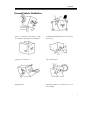
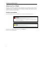
Hardware Installation Guide
Revision2.1
Preface
Preface
C
Cooppyyrriigghhtt 22000033
All rights Reserved- Printed in Taiwan
N
Noottiiccee
We make no warranties with respect to this documentation either express or implied and provide it "as
it". This includes but is not limited to any implied warranties of merchantability and fitness for a
particular purpose. The information in this document is subject to change without notice. We assume
no responsibility for any errors that may appear in this document.
The manufacturer shall not be liable for any damage, or for the loss of information resulting from the
performance or use of the information contained herein
T
Trraaddeem
maarrkkss
Product names used herein are for identification purposes only and may be the trademarks of their
respective companies. All trademarks or registered trademarks are properties of their respective
owners.
1
Hardware Installation Guide
R
Reegguullaattoorryy iinnffoorrm
maattiioonn
For Europe
This drive is in conformity with the EMC directive.
Federal Communications Commission (FCC) Statement
This equipment has been tested and found to comply with the limits for a Class A digital device,
pursuant to part 15 of the FCC Rules.
Those limits are designed to provide reasonable protection against harmful interference in a residential
installation. This equipment generates, uses and can radiate radio frequency energy and, if not installed
and used in accordance with the instructions, may cause harmful interference to radio communications.
However, there is no guarantee that interference will not occur in a particular installation. If this
equipment does cause harmful interference to radio or television reception, which can be determined
by turning the equipment off and on, the user is encouraged to try to correct the interference by one or
more of the following measures:
Reorient or relocate the receiving antennas.
Increase the separation between the equipment and receiver.
Connect the equipment into an outlet on a circlet different from that to which the receiver is connected.
Consult the dealer or an experienced radio/TV technician for help.
Warning:
A shielded-type power cord is required in order to meet FCC emission limits and also to prevent
interference to the nearby radio and television reception. It is essential that only the supplied power
cord be used.
Use only shielded cables to connect I/O devices to this equipment.
You are cautioned that changes or modifications not expressly approved by the party responsible for
compliance could void your authority to operate the equipment.
2
Preface
G
Geenneerraall SSaaffeettyy G
Guuiiddeelliinneess
DO NOT place the RAID SYSTEM on
uneven or unstable work surfaces. Seek
servicing if the casing has been damaged.
DO NOT place or drop objects on top of the
RAID SYSTEM and do not shove any foreign
object into it.
DO NOT expose RAID SYSTEM to
liquids, rain, or moisture.
DO NOT expose RAID SYSTEM to dirty or
dusty environments.
DO NOT expose RAID SYSTEM to
magnetic field.
DO NOT expose RAID SYSTEM to extreme
temperatures (below 5”C or above 45”C) or to
direct sunlight.
3
Hardware Installation Guide
A
Abboouutt yyoouurr U
Usseerr’’ss G
Guuiiddee
Welcome to your Hardware Installation Guide. This manual covers everything you need to know in
learning how to install your RAID system. This manual also assumes that you know the basic concepts
of RAID technology. For the detail about how to configure your RAID system, please refer to the
RAID system Software Operation manual.
G
Guuiiddee ttoo ccoonnvveennttiioonnss
Important information that users should be aware of is indicated with the following icons:
This icons indicates the existence of a potential hazard that could result in
personal injury, damage to your equipment or loss of data if the safety
instruction is not observed.
This icon indicates useful tips on getting the most from your RAID controller.
Important terms, commands and programs are put in Boldface font.
Screen text is given in screen font.
4
Table of Contents
T
Ta
ab
bllee o
off C
Co
on
ntteen
nttss
PREFACE........................................................................................................................ 1
COPYRIGHT 2003........................................................................................................ 1
NOTICE ....................................................................................................................... 1
TRADEMARKS ............................................................................................................. 1
REGULATORY INFORMATION ...................................................................................... 2
GENERAL SAFETY GUIDELINES .................................................................................. 3
ABOUT YOUR USER’S GUIDE ...................................................................................... 4
GUIDE TO CONVENTIONS ............................................................................................ 4
T
T
A
B
L
E
O
F
C
O
N
T
E
N
T
S
TA
AB
BL
LE
EO
OF
FC
CO
ON
NT
TE
EN
NT
TS
S ................................................................................... 5
CHAPTER 1 ............................................................................................................ 7
CHAPTER 1 ............................................................................................................ 7
INTRODUCTION ................................................................................................. 7
FEATURE HIGHLIGHT .................................................................................................. 7
BEFORE YOU BEGIN .................................................................................................... 8
Unpacking & Checking The Equipment ............................................................... 8
What else you need ............................................................................................ 9
IDENTIFYING PARTS OF THE RAID SYSTEM ............................................................. 10
Front View.......................................................................................................... 10
Rear View ........................................................................................................... 15
SPACE REQUIREMENT ............................................................................................... 18
SYSTEM CONNECTION .............................................................................................. 18
Cable .................................................................................................................. 18
RAID system ....................................................................................................... 18
Device................................................................................................................. 18
Purpose............................................................................................................... 18
INSTALL HARD DISKS ................................................................................................ 19
CHAPTER 2 .......................................................................................................... 20
H
H
A
R
D
W
A
R
E
N
S
T
A
L
L
A
T
O
N
HA
AR
RD
DW
WA
AR
RE
E IIIN
NS
ST
TA
AL
LL
LA
AT
TIIIO
ON
N ................................................................ 20
5
Hardware Installation Guide
REPLACE THE CONTROLLER ..................................................................................... 20
REPLACING / UPGRADING SODIMM....................................................................... 24
SODIMM specifications: (Applied on PA-08/BR-8000, SA-16/PA-16, &.......... 24
BR-1200/BR-1600)............................................................................................. 24
Architecture of supported SODIMM:................................................................. 25
SODIMM specifications:(Applied on PA-08P/SA-08P, PA-16P/SA-16P) ......... 26
Architecture of supported SODIMM:................................................................. 26
Installing SODIMM............................................................................................ 27
HOT SWAPPING TO REPLACE THE FAN MODULE ....................................................... 28
HOT SWAPPING TO REPLACE THE POWER MODULE .................................................. 29
TURNING ON FOR THE FIRST TIME ............................................................................. 30
TURNING OFF............................................................................................................ 30
RESTARTING ............................................................................................................. 30
APPENDIX A ....................................................................................................... 31
T
T
R
O
U
B
L
E
S
H
O
O
T
N
G
TR
RO
OU
UB
BL
LE
ES
SH
HO
OO
OT
TIIIN
NG
G ................................................................................. 31
APPENDIX B ....................................................................................................... 35
C
C
O
N
N
E
C
T
O
R
S
CO
ON
NN
NE
EC
CT
TO
OR
RS
S.................................................................................................... 35
APPENDIX C ....................................................................................................... 37
S
S
P
E
C
F
C
A
T
O
N
S
SP
PE
EC
CIIIF
FIIIC
CA
AT
TIIIO
ON
NS
S ............................................................................................ 37
6
Chapter 1 – Introduction
Chapter 1
Introduction
This chapter introduces the features and capabilities of RAID SYSTEM.
You will find:
A
Affuullll iinnttrroodduuccttiioonn ttoo yyoouurr R
RA
AIID
D SSY
YSSTTEEM
M
D
Deettaaiillss ooff kkeeyy ffeeaattuurreess aanndd ssuupppplliieedd aacccceessssoorriieess
A
Acchheecckklliisstt ooff ppaacckkaaggee ccoonntteennttss
A
Acchheecckklliisstt ooff w
whhaatt eellssee yyoouu nneeeedd ttoo ssttaarrtt iinnssttaallllaattiioonn
FFeeaattuurree H
Hiigghhlliigghhtt
The RAID SYSTEM is designed to meet today’s high volume, performance storage
requirements from rapidly changing business environment. It provides a maximum data
protection and exceptional performance in a storage subsystem. Target usage ranges are set from
small business to departmental and corporate server needs. The RAID SYSTEM is designed for
easy integration, smooth data expansion and server migration.
The RAID SYSTEM supports the following features:
* Host System independent
* Operating System independent
* High performance processor
* Superior Array Management Firmware
* Advanced PCI bus architecture
* Flexible cache size of up to 512MB/1GB
* Support for RAID Levels 0, 1,3, 5,30,50 and 0+1
* Dual Ultra-160 /Ultra-320 SCSI Host Interconnect support by SCSI to ATA model
* Dual Loop of 2Gb/sec Fibre Channel support by Fibre to ATA model
* Redundant and Hot Swappable Fan, Power and Drives.
* Hot Swap, Hot Spare and Automatic Drive Rebuild Support
* Programmable Page and FAX event notification
7
Hardware Installation Guide
* Remote monitoring through terminal
* Load-sharing hot swappable redundant power system with PFC function .
B
Beeffoorree yyoouu bbeeggiinn
Unpacking & Checking The Equipment
Before unpacking the RAID SYSTEM, prepare a clean, stable surface to put on the contents of
your RAID SYSTEM shipping container. Altogether, you should find the following items in the
package:
SCSI to ATA RAID System
RAID System x1
RAID system Hardware Installation Guide x1 (CD media or Hard Copy)
RAID system Software Operation Manual x1 (CD media or Hard Copy)
Ultra320 SCSI Cable x1
RS232 cable x1
Ultra320 SCSI Active Terminator x1
Power Cord x1
Mounting screws (bag) ×1
Fibre to ATA RAID system
RAID System x1
RAID system Hardware Installation Guide x1 (CD media or Hard Copy)
RAID system Software Operation Manual x1 (CD media or Hard Copy)
RS232 cable x1
Power Cord x1
Mounting screws (bag) ×1
8
Chapter 1 – Introduction
To avoid the unmatched cable between the Fibre HBA in the Host and
Fibre-ATA RAID SYSTEM, Fibre-ATA RAID system doesn’t include the Fibre
interface with the standard configuration. There are many different kinds of
Fibre connectors on varied of Fibre HBAs.
What else you need
Hard disk drives (different RAID levels requires different numbers of HDDs.
Refer to Software Operation manual for more detail information.
Host computer with SCSI interface (SCSI-ATA RAID SYSTEM)
Host computer with Fibre interface (Fibre-ATA RAID SYSTEM)
Static grounding strap or electrostatic discharge (ESD) safe work area
Dedicated terminal or PC with third party communication software that supports
ANSI terminal emulation (required for viewing Monitor Utility)
The hard drives in a RAID system should match in size and speed. All drives in
any array should be identical models with the same firmware versions. RAID
system can use any size drive, however the smallest drive will determine the
size of the array.
There's no set formula to determine how much cache memory to use, but as a
general rule, a workstation, with mostly very large files, such as for audio or
video editing and playback, graphics or CAD files, can benefit from a large
cache. File servers, with multiple random access of varying file size, generally
have little or no performance improvement with additional cache.
RAID system do not require the installation of different drivers for use with
different operating systems. RAID system is independent and transparent to
the host operating system.
9
Hardware Installation Guide
IIddeennttiiffyyiinngg PPaarrttss O
m
Off T
Thhee R
RA
AIID
D ssyysstteem
The illustrations below identify the various parts of the RAID SYSTEM. Get yourself to familiar
with these terms as it will help you when you read further in the following sections :
Front View
SA-16/SA-16P/PA-16/PA-16P
PA-08/PA-08P/SA-08P
10
Chapter 1 – Introduction
BR-1600-R
2.
1.
3.
6.
8
9
10
7.
5.
4.
BR-1600-D
7
1
8
9
10
2
6
5
4
3
11
Hardware Installation Guide
BR-1200-R
2.
1.
7.
8
9
10
3.
6.
5.
4.
BR-1200-D
1
8
9
10
5
2
6
4
3
12
Chapter 1 – Introduction
BR-8000-R
BR-8000-D
1.
LCD Display Panel.
The front panel LCD continuously displays the status of the RAID SYSTEM. The following is an
example of the RAID SYSTEM
2.
Disk Cartridge
3.
Cartridge Handle
4.
Release-Button
13
Hardware Installation Guide
5.
Latch
LOCK
UNLOCK
6.
HDD status LED Indicator
LED
Colors
Indicate
Blue
HDD On Line
or Green
Blue + Blink HDD Access
or Amber
?
7.
8.
9.
10.
14
Red
HDD Error
Function keys. ( ENT , ESC, Scroll up , Scroll Down )
Keys
Descriptions
Up Arrow
To scroll upward through the menu items
Down Arrow
To scroll downward through the menu items
(ENT ) Enter
To confirm a selected item
(ESC) ESC
To exit a sub-menu and return to previous menu.
Power On Indicator (Blue or Green).
Power Fail Indicator (Red)
Host System Access Indicator (Blue + blink or Yellow).
Chapter 1 – Introduction
Rear View
SA-16U3/SA-16U4P/PA-16U4P
SA-16FC/SA-16FCP/PA-16U4P
PA-16U3
PA-16FC
PA-08U3/PA-08U4P/SA-08U3/SA-08U4P
PA-08FC/PA-08FCP/SA-08FC/SA-08FCP
15
Hardware Installation Guide
BR-1200/1600
BR-1200U3/1600U3.
9.
11.
4.
1.
3.
15.
11.
15.
13.
2.
5.
8.
10.
15.
6.
8.
14.
7.
8.
4.
3.
BR-1200FC/1600FC.
BR-8000D
BR-8000U3.
3.
16
4.
Chapter 1 – Introduction
BR-8000R
1.
RS232 Port (For Terminal)
2.
Modem Port
SCSI-ATA RAID SYSTEM:
4.
3.
Primary Host SCSI Channel Port
Second Host SCSI Channel Port
Fibre-ATA RAID SYSTEM:
3.
1st Fibre Channel Loop
4.
2nd Fibre Channel Loop
5.
System Cooling Module 1.
6.
System Cooling Module 2.
7.
System Cooling Module 3.
8.
System Cooling Module Fail Indicator.
9.
Power Switch
10.
AC Inlet with the Latch
11.
Power Supply “Alarm” Reset Button.
12.
Power Module 1.
13.
Power Module 2.
14.
Power Module 3.
15.
Power Indicator LED on Module.
16.
LAN Port
17
Hardware Installation Guide
SSppaaccee R
Reeqquuiirreem
meenntt
When selecting a location for your system, be sure to allow an adequate space. The system has
vents around it which will require a minimum of 3 inches of unobstructed space for airflow.
Openings in the equipment should be blocked, or there may be an issue of reliability problems
with your system. A system product should never be place around a radiator or heat register.
SSyysstteem
mC
Coonnnneeccttiioonn
Connect all cables and power cord as shown below:
Cable
RAID system
Device
Purpose
RS-232 cable RS-232 Port
ANSI Terminal or a PC with Terminal
Utility
for
Hyper terminal
configuration and Monitoring
SCSI Cable / Primary
SCSI/FC-AL or
Fibre cable
Secondary
SCSI/FC-AL
SCSI/FC-AL
Computer
Power Cord
A/C Power Outlet
A/C power input
Modem
Event notification via Fax and
page
Power Inlet
RS-232 cable Modem Port
HBA of Host Host Interface
Make sure that all the devices are powered off before connecting or removing
cables to prevent power spikes which can damage technical components.
18
Chapter 1 – Introduction
IInnssttaallll hhaarrdd ddiisskkss
The RAID SYSTEM includes 8/12/16 ( depending on your models) removable disk cartridges.
The following sections describe how to install disks into RAID SYSTEM subsystems.
Remove Cartridges
Slide the latch to unlock.
Release the handle by sliding lift the release button.
Lift the handle to disengage the disk cartridge from
the slot.
Install HDDs.
Put HDD into the Cartridge.
Skip this procedure if you are using SATA HDDs.
Connect the flat cable to the HDD. Make sure pin1
(also designated by the color strip) of the cable is
aligned with pin1 of disk connector.
Skip this procedure if you are using SATA HDDs.
Connect the power cable to the power connector of
HDD.
Fasten all 4 screws to mount HDD in the cartridge
and make sure the HDD is properly tightened.
Install Cartridges
Reversed the procedures of “Remove cartridges” to
install cartridges back to RAID system .
19
Hardware Installation Guide
Chapter 2
H
Ha
arrd
dw
wa
arree IIn
nsstta
alllla
attiio
on
n
This chapter presents:
IInnssttrruuccttiioonnss oonn rreeppllaacciinngg ccoom
mppoonneennttss
IInnssttrruuccttiioonnss oonn rreeppllaacciinngg tthhee hhoott ssw
waappppaabbllee ccoom
mppoonneennttss
IInnssttrruuccttiioonnss oonn hhoow
t
o
i
n
s
t
a
l
l
a
n
d
u
p
g
r
a
d
e
D
R
A
w to install and upgrade DRAM
M
R
Reeppllaaccee tthhee C
Coonnttrroolllleerr
Read the replacing notices earlier in this chapter before proceeding with
replacement.
This section provides instructions for the removal and installation of the RAID controller
components indicated in the figure below. This section is for the reference of engineers. End
users should not need to replace or remove components.
20
Chapter 2 – Hardware Installation
Removing the controller from PA-08/PA-16/SA-16:
Unscrew the Fasteners of Bracket then slide it back.
Disconnect the host cables.
Turn anti-clock wise to release the thumb screw.
Use the eject kit to remove controller board.
PA-08/SA-08/SA-08P
PA-16
SA-16/SA-16P/PA-16P
Installing the controller into PA/08/PA-16/SA-16:
Reverse the procedures as above to install the controller into SA-16/PA-16.
Then according to “Appendix C. Configuration table” on “Soft Operation Manual” to reconfigure
your RAID
21
Hardware Installation Guide
Removing the controller from BR-8000D/R :
In order to access internal components, remove
the controller box cover by unscrew the
fasteners of the cover and then slide it back and
lift it off.
Disconnect the host cables, then unscrew four
fasteners on the controller and lift upward to
remove it.
Installing the controller into BR-8000D/R :
Reverse the procedure of “removing the controller” to install the controller into BR-8000.
Then according to “Appendix C. Configuration table” on “Soft Operation Manual” to
reconfigure your RAID
22
Chapter 2 – Hardware Installation
Removing the controller from BR-1200 & BR-1600:
Remove the Fan modules by anti-clock wise to
release the thumb screws then slide it back and lift it
off.
Unscrew the two fasteners on the bracket and
backward to remove the bracket
Disconnect the host cables
Turn anti-clock wise to release the thumb screw,
then use the eject kit to remove controller board
Installing the controller into BR-1200/1600 :
Reverse the procedures as above to install the controller into BR-1200/BR-1600.
Then according to “Appendix C. Configuration table” on “Soft Operation Manual” to reconfigure
your RAID
23
Hardware Installation Guide
R
Reeppllaacciinngg // U
Uppggrraaddiinngg SSO
OD
DIIM
MM
M
Read the pre-installation notices earlier in this chapter before proceeding with
installation.
RAID SYSTEM is normally supplied with 64MB (PA-08/BR-8000) and 128MB (SA-16/PA-16/
BR-1200/BR1600) DRAM installed.
There's no set formula to determine how much cache memory to use, but as a
general rule, a workstation, with mostly very large files, such as for audio or
video editing and playback, graphics or CAD files, can benefit from a large
cache. File servers, with multiple random access of varying file size, generally
have little or no performance improvement with additional cache.
SODIMM specifications: (Applied on PA-08/BR-8000, SA-16/PA-16, &
Minimum
BR-1200/BR-1600)
Recommended
144-pin SDRAM SODIMM module
(PC-100, 60~80 ns).
SDRAM
SODIMM, without parity
Minimum of one SODIMM with 32 MB.
The memory card socket can support 32,
64, 128, 256 or 512 MB of memory.
24
Minimum of 32 MB. More memory
(up to 512MB) equals better
performance: the size of the memory
module defines the cache writing
space available to the RAID
SYSTEM.
Chapter 2 – Hardware Installation
The RAID system controller board already implement a 512Mb memory for
the propose of Parity bit to support the ECC feature. There is no need to install
the SODIMM with parity.
Architecture of supported SODIMM:
SDRAM Architecture
512 MB
16 (32M x 8)
256 MB
16 (16M x 8), 8 (32M x 8) or
8 (16M x 16)
128 MB
16 (8M x 8), 8 (16M x8), 8 (8M x16) or
4 (16M x 16)
64 MB
8 (8M x 8), 8 (4M x 16) or
4 (8M x 16)
32 MB
4 (4M x 16)
RAID SYSTEM is normally supplied with 64MB (PA-08P/SA-08P) and 128MB (SA-16P/
PA-16P) DRAM installed.
There's no set formula to determine how much cache memory to use, but as a
general rule, a workstation, with mostly very large files, such as for audio or
video editing and playback, graphics or CAD files, can benefit from a large
cache. File servers, with multiple random access of varying file size, generally
have little or no performance improvement with additional cache.
25
Hardware Installation Guide
SODIMM specifications:(Applied on PA-08P/SA-08P, PA-16P/SA-16P)
Minimum
Recommended
200-pin SDRAM SODIMM module
(PC-200).
DDR
SODIMM, with or without parity
With Parity, for security
Minimum of one SODIMM with 64 MB.
The memory card socket can support ,
64, 128, 256 , 512 MB or 1GB of
memory.
Minimum of 64MB. More memory
(up to 1GB) equals better
performance: the size of the memory
module defines the cache writing
space available to the RAID
SYSTEM.
Architecture of supported SODIMM:
SDRAM Architecture
26
1GB
16 (64M bit x 8)
512 MB
16 (32M bit x 8), 8 (32M bit x 16) or
8 (64M bit x 8)
256MB
16 (16M bit x 8), 8 (32M bit x8), 8 (16M bit x 8) or
4 (32M bit x 16)
128 MB
8 (16M bit x 8), 8 (8M bit x 16) or
4 (16M bit x 16) , 16 (8M bit x8)
64 MB
4 (8M bit x 16) , 8 (8M bit x8)
Chapter 2 – Hardware Installation
Installing SODIMM
To install a SODIMM, ensure the system is power off and disconnected. Then:
1.
Unscrews three fasteners.
2.
Remove the daughter board.
3.
Insert a memory card at a 45-degree angle into
the memory card socket so that the gold teeth
of the card are no longer visible.
4.
Press the card down firmly until the latches
lock it into place.
Before starting any kind of hardware installation, please ensure that all power
switches have been turned off and all power cords disconnected to prevent
personal injury and damage to the hardware
Use screws provided with RAID system only. Longer or shorter screws may
cause electric shorting or un-proper installed.
Static electricity can damage electronic components. To guard against such
damage:
Work in a static-free environment
Wear a grounded anti-static wrist strap
Store uninstalled components in anti-static bags
Handle PCBs by their edges and avoid touching chips and connectors.
27
Hardware Installation Guide
H
Hoott SSw
waappppiinngg ttoo rreeppllaaccee tthhee FFaann M
Moodduullee
This section provides instructions for the removal and installation of the Fan Module indicated in
the figure below.
SA-16/PA-16/PA-08
Removing the Fan Module from RAID
system :
Remove the Fan modules by anti-clock wise to
release the thumb screw then slide it back and
lifting off.
Installing the Fan module into RAID
system :
Insert a Fan module then fasten the thumb
screw clock wise .
28
BR-8000/BR-1200
BR-1600
Chapter 2 – Hardware Installation
H
Hoott SSw
Moodduullee
waappppiinngg ttoo rreeppllaaccee tthhee PPoow
weerr M
This section provides instructions for the removal and installation of the Fan Module indicated in
the figure below.
Removing the Power Module from RAID
system PA-08 :
Removing the Power Module from RAID
system BR-8000 :
Unscrew the fastener then slide it back and
lifting off.
Unscrew the fastener then slide it back and
lifting off.
Removing the Power Module from RAID
system SA-16/PA-16 :
Removing the Power Module from RAID
system BR-1200/1600 :
Unscrew the fastener then slide it back and
lifting off.
Unscrew the fastener then slide it back and
lifting off.
Installing the Power module into RAID
system :
Insert a Power module then fasten the screw.
The Power indicator will turn bright “Green” to indicate it has powered on
29
Hardware Installation Guide
T
Tuurrnniinngg oonn ffoorr tthhee ffiirrsstt ttiim
mee
When cabling is completed, RAID SYSTEM can be turned on. This should be done in the
following order:
1.
First turn on the power switch of RAID SYSTEM.
2.
Then power on and boot the host computer(s)
When RAID SYSTEM is running, you are ready to configure one or more RAID arrays. You
have the following options:
1.
Turn to Chapter 3 of “Software Operation Manual” to perform a quick setup of a single
RAID array using the control panel.
2.
Turn to Chapter 4 of “Software Operation Manual” to access the Monitor Utility. Once the
Monitor Utility is accessed, you can perform a Quick Setup (Chapter 3) or complete
configuration (Chapter 5) with either the control panel or Monitor Utility.
3. Turn to Chapter 5 of “Software Operation Manual” to perform a full configuration using the
control panel.
T
Tuurrnniinngg ooffff
When turning off RAID SYSTEM, users are advised to first shut down the server, then power off
RAID SYSTEM.
R
Reessttaarrttiinngg
When restarting RAID SYSTEM, users are advised to first restart the server, then power on
RAID SYSTEM.
30
Appendix A – Troubles Shooting
Appendix A
T
Trro
ou
ub
bllee S
Sh
ho
oo
ottiin
ng
g
Problems setting up
Newly installed memory fails during Self-Test or is not detected.
Possible Cause: The Memory SO-DIMM module may not be properly seated or may not be
supported by RAID SYSTEM.
Fix: Re-sit the memory module in the socket and retry. If it continues to fail try moving it to the
other memory socket. Make sure the correct memory type is being installed. RAID SYSTEM
supports 144-pin SO-DIMM SDRAM.
Unable to access RAID SYSTEM after the operating system boots up.
Possible Cause: RAID SYSTEM is not configured.
Fix: Make sure RAID SYSTEM is configured for a RAID level. If no RAID level is configured
the operating system will not detect RAID SYSTEM as a disk drive.
RAID SYSTEM does not recognize the HDDs
Possible Cause: HDD jumper setting problem.
Fix: Make sure all drive jumpers are set to "master"
I try to set up an array using Quick Setup but fail. Why?
Possible Cause: If the error message Array1 Exists! appears, an array has already been
configured. Quick Setup can only be used to new RAID arrays.
Fix: Reconfigure the array from the RAID params submenu
Problems during operation
The front panel LCD displays alternating “Zz” characters.
Possible Cause: These characters are displayed when the cache is full with write request data that
have not been processed. Requests from the host are halted to flush the data in the cache.
Fix: None needed.
The front panel LCD displays alternating “Ww” characters.
Possible Cause: These characters are displayed to indicate that write requests in the cache are
31
Hardware Installation Guide
being processed. When these characters are displayed, RAID SYSTEM will halt requests from
the host (see above).
Fix: Make sure the Write Buffer option of the RAID Params menu is enabled. In addition, more
cache memory may be required. By increasing the cache memory, the write buffer space
increases and will be able to handle the higher write requests.
LCD display shows OWOOOS
Possible Cause: “W” means “warning” - there are many bad sectors on your HDD.
Fix: Change hard drives.
Invalid NVRAM message appears
Possible Cause: NVRAM error or malfunction.
Fix: Save settings and restart the controller. If the problem persists, contact your vendor.
Data loss for Windows 2000 during system shutdown
Possible Cause: RAID controller is in a process of a built-in host and some data is still in cache
buffer during system shutdown.
Fix 1: Set Cache Off
Fix 2: To shutdown, select Restart system and wait for 30 seconds, then power off the system.
Fix 3: Shutdown host OS after shutting down controller.
Remote terminal problems
Unable to access Configuration Mode using the remote terminal interface.
Possible Cause 1: The terminal communication settings do not match the settings of the RAID
SYSTEM RS-232 interface.
Fix: The default settings for the RS-232 port are 19,200 Baud rate, 8 Data bits, 1 Stop bit, No
Parity, and XON/XOFF Flow control. Make sure the terminal is configured for these settings. If
the settings were changed in Configuration Mode, verify the settings of the RAID SYSTEM in
the RS-232 Params, Terminal option and change the terminal settings accordingly.
Possible Cause 2: Incompatible RS232 cable.
Fix: Cross pins on the RS-232 cable as shown below (or use a null modem cable). The only pins
used are 2 3 & 5.
32
Appendix A – Troubles Shooting
123456789
X I
123456789
Alert message problems
I am unable to send a Page or FAX using the modem port.
Possible Cause 1: The Page and Fax options are not enabled.
Fix: Go to the Configuration Mode and enable Page and FAX notification via the System Params
menu option.
Possible Cause 2: The default modem initialization string is not compatible with your modem.
Fix: Change the modem initialization string in the System Params option. Refer to your modem
manual for its initialization string.
The following modem models require their own initialization strings.
Modem Model
Initialization String
Baud Rate
FAX Class
Motorola
AT&D\Q1E
Up to 38400
1&2
ModemSURFR
V.34 28.8
Multitech
AT&D0&E5E0
Up to 38400
2 only
Multimodem
2834ZDX
Hayes
AT&D0&K4E0
38400 only
1&2
AT&K4
Up to 38400
2 only
PM144MT II
GVC F-1128V/T2 AT&D0&B1&H2
38400 only
1&2
US Robotics
38400 only
1 only
Accura
V.34+FAX
Practical
Peripherals
288
AT&H2&I1&R1&B1
Sportster 28800
33
Hardware Installation Guide
SCSI problems
RAID SYSTEM is not properly identified by the SCSI adapter during initialization of the
computer system.
Possible Cause: The SCSI ID set for the RAID SYSTEM is being used by another SCSI device
attached to the same SCSI card.
Fix: Select the Set SCSI ID option from the SCSI Params menu and specify a different SCSI ID.
Most SCSI host adapters provide an onboard ROM BIOS, or software utility, that displays the
devices attached and their SCSI IDs. Disconnect RAID SYSTEM from the SCSI host adapter
card and during the system boot, or by running the utility, note the SCSI IDs already in use.
The RAID SYSTEM is identified as all SCSI IDs.
Possible Cause: The SCSI ID set for RAID SYSTEM is identical to the reserved SCSI ID used by
the SCSI card in your system.
Fix: Select the Set SCSI ID option from the SCSI Params menu and specify a different SCSI ID.
Most SCSI host adapter cards reserve SCSI ID 7 for the card ID.
The SCSI host adapter card does not detect RAID SYSTEM.
Possible Cause: Incorrect termination in a daisy chain configuration or a loose cable in a
stand-alone configuration.
Fix: In a daisy chain configuration, verify that only the SCSI host adapter and the last SCSI
device is terminated. To change termination settings of RAID SYSTEM, use the SCSI Params
menu SCSI Termination option to enable or disable termination.
34
Appendix B – Connectors
Appendix B
C
Co
on
nn
neecctto
orrss
SCSI Connector
1
34
35
68
Pin#
Signal Name
Pin#
Signal Name
1
SCSI_AC_DAT<12>+
35
SCSI_AC_DAT<12>-
2
SCSI_AC_DAT<13>+
36
SCSI_AC_DAT<13>-
3
SCSI_AC_DAT<14>+
37
SCSI_AC_DAT<14>-
4
SCSI_AC_DAT<15>+
38
SCSI_AC_DAT<15>-
5
SCSI_AC_PAR<1>+
39
SCSI_AC_PAR<1>-
6
SCSI_AC_DAT<0>+
40
SCSI_AC_DAT<0>-
7
SCSI_AC_DAT<1>+
41
SCSI_AC_DAT<1>-
8
SCSI_AC_DAT<2>+
42
SCSI_AC_DAT<2>-
9
SCSI_AC_DAT<3>+
43
SCSI_AC_DAT<3>-
10
SCSI_AC_DAT<4>+
44
SCSI_AC_DAT<4>-
11
SCSI_AC_DAT<5>+
45
SCSI_AC_DAT<5>-
12
SCSI_AC_DAT<6>+
46
SCSI_AC_DAT<6>-
13
SCSI_AC_DAT<7>+
47
SCSI_AC_DAT<7>-
14
SCSI_AC_PAR<0>+
48
SCSI_AC_PAR<0>-
15
GND
49
GND
16
GND
50
GND
17
TERMPWRA
51
TERMPWRA
18
TERMPWRA
52
TERMPWRA
19
GND
53
GND
20
GND
54
GND
21
SCSI_AC_ATN_L+
55
SCSI_AC_ATN_L-
22
GND
56
GND
23
SCSI_AC_BSY_L+
57
SCSI_AC_BSY_L-
24
SCSI_AC_ACK_L+
58
SCSI_AC_ACK_L-
25
SCSI_AC_RST_L+
59
SCSI_AC_RST_L-
26
SCSI_AC_MSG_L+
60
SCSI_AC_MSG_L-
27
SCSI_AC_SEL_L+
61
SCSI_AC_SEL_L-
28
SCSI_AC_CD_L+
62
SCSI_AC_CD_L-
29
SCSI_AC_REQ_L+
63
SCSI_AC_REQ_L-
30
SCSI_AC_IO_L+
64
SCSI_AC_IO_L-
31
SCSI_AC_DAT<0>+
65
SCSI_AC_DAT<0>-
32
SCSI_AC_DAT<9>+
66
SCSI_AC_DAT<9>-
33
SCSI_AC_DAT<10>+
67
SCSI_AC_DAT<10>-
34
SCSI_AC_DAT<11>+
68
SCSI_AC_DAT<11>-
35
Hardware Installation Guide
FC-AL HSSDC. Connector
1
8
Pin#
Signal Name
1
TX+
2
Ground
3
TX-
4
Fault-
5
ODIS
6
RX-
7
+5VDC
8
RX+
RS-232 & Modem Male Connector
Pin#
1
2
3
4
5
36
Signal
DCD
RXD
TXD
DTR
GND
Pin#
6
7
8
9
Signal
DSR
RTS
CTS
TXC
Appendix C – Specification
Appendix C
S
Sp
peecciiffiicca
attiio
on
nss
SA-16U4P/FCP
Model
RAID Engine
RAID Levels
Cache Support
(Write back)
System Type
Host Interface
SA-16P
U4
Intel i80321 64bit RISC CPU
0, 1, 3, 5,30,50 or 0+1
Up to 1GBMbytes with ECC 200pins DDRAM Memory
Rack mountable
Dual Ultra 320 SCSI Channels
Host Transfer Rate
320MB / Sec per channel
Disk Interface
Disk Channel
LCD Display
Hot Swap and
redundant
Hot Spare
Battery Back-Up
Module
UART – LAN
SATA 1.5Gbps
Sixteen SATA 1.5Gb Disk Channels
2 Lines by 16 Characters
Yes (Power Supply, Drive and Fan).
FC bypass module
Array Management
Support
Automatic Bad-Sector
& Error Recovery
Automatic Drive
Rebuilds
Audible Alarm, Pager
and Fax Notification
Remote Terminal
Configuration
Operating Systems
Power Supply
Electrical
Temperature
Relative Humidity
Dimensions
Weight
FC
Dual loops 2Gb Fibre Channels, Standard SFP
connectors
2Gb/ Sec per loop
Yes (Drive).
Optional, Support up to 72hrs battery back-up time (N.A.)
Optional, Window-Based GUI RAID manager designed for SCSI/FC host based RAID
solutions. The OS-independent, cross-platform RAID management allows configuration and
status monitoring via standard web browsers or host computers either directly connected to a
LAN or WAN.
Optional, Connecting each RAID systems with in-build FC hub adaptors, provides the greater
extension availability, No need extra External FC Hub or Switch.
Yes.
Yes.
Yes. Automatic Data rebuilds.
Yes. The Pager and Fax Notification have to connect a external modem.
Yes. Through RS-232 emulation terminal.
O/S Independent and Transparent
700+350 watts Redundancy high quality power system, three 350 watts module with PFC
function. Load sharing type and cable-less design with Redundancy Dual Power inlet
AC Voltage 100-240 VAC
Ac Frequency 47-63Hz
Operating Temperature : 5 to 35 degree C.
Non Operating Temperature : -40 to 60 degree C.
20% to 80% non-condensing
446.4(W)*440.4(D)*3U(H)
28KG
37
Hardware Installation Guide
PA-16U4P/FCP
Model
RAID Engine
RAID Levels
Cache Support
(Write back)
System Type
Host Interface
SA-16P
U4
Intel i80321 64bit RISC CPU
0, 1, 3, 5,30,50 or 0+1
Up to 1GBMbytes with ECC 200pins DDRAM Memory
Rack mountable
Dual Ultra 320 SCSI Channels
Host Transfer Rate
320MB / Sec per channel
Disk Interface
Disk Channel
LCD Display
Hot Swap and
redundant
Hot Spare
Battery Back-Up
Module
UART – LAN
EIDE, ATA-100
Sixteen of UltraDMA100 Disk Channel
2 Lines by 16 Characters
Yes (Power Supply, Drive and Fan).
FC bypass module
Array Management
Support
Automatic Bad-Sector
& Error Recovery
Automatic Drive
Rebuilds
Audible Alarm, Pager
and Fax Notification
Remote Terminal
Configuration
Operating Systems
Power Supply
Electrical
Temperature
Relative Humidity
Dimensions
Weight
38
FC
Dual loops 2Gb Fibre Channels, Standard SFP
connectors
2Gb/ Sec per loop
Yes (Drive).
Optional, Support up to 72hrs battery back-up time (N.A.)
Optional, Window-Based GUI RAID manager designed for SCSI/FC host based RAID
solutions. The OS-independent, cross-platform RAID management allows configuration and
status monitoring via standard web browsers or host computers either directly connected to a
LAN or WAN.
Optional, Connecting each RAID systems with in-build FC hub adaptors, provides the greater
extension availability, No need extra External FC Hub or Switch.
Yes.
Yes.
Yes. Automatic Data rebuilds.
Yes. The Pager and Fax Notification have to connect a external modem.
Yes. Through RS-232 emulation terminal.
O/S Independent and Transparent
700+350 watts Redundancy high quality power system, three 350 watts module with PFC
function. Load sharing type and cable-less design with Redundancy Dual Power inlet
AC Voltage 100-240 VAC
Ac Frequency 47-63Hz
Operating Temperature : 5 to 35 degree C.
Non Operating Temperature : -40 to 60 degree C.
20% to 80% non-condensing
446.4(W)*493.6(D)*3U(H)
28KG
Appendix C – Specification
SA-16U3/FC
Model
RAID Engine
RAID Levels
Cache Support
(Write back)
System Type
Host Interface
SA-16
U3
Intel i80303 64bit RISC CPU
0, 1, 3, 5 or 0+1
Up to 512Mbytes with ECC 144pins SDRAM Memory
Rack mountable
Dual Ultra 160 SCSI Channels
Host Transfer Rate
160MB / Sec per channel
Disk Interface
Disk Channel
LCD Display
Hot Swap and
redundant
Hot Spare
Battery Back-Up
Module
UART – LAN
SATA 1.5Gbps
Sixteen SATA 1.5Gb Disk Channels
2 Lines by 16 Characters
Yes (Power Supply, Drive and Fan).
FC bypass module
Array Management
Support
Automatic Bad-Sector
& Error Recovery
Automatic Drive
Rebuilds
Audible Alarm, Pager
and Fax Notification
Remote Terminal
Configuration
Operating Systems
Power Supply
Electrical
Temperature
Relative Humidity
Dimensions
Weight
FC
Dual loops 2Gb Fibre Channels, Standard SFP
connectors
2Gb/ Sec per loop
Yes (Drive).
Optional, Support up to 72hrs battery back-up time (N.A.)
Optional, Window-Based GUI RAID manager designed for SCSI/FC host based RAID
solutions. The OS-independent, cross-platform RAID management allows configuration and
status monitoring via standard web browsers or host computers either directly connected to a
LAN or WAN.
Optional, Connecting each RAID systems with in-build FC hub adaptors, provides the greater
extension availability, No need extra External FC Hub or Switch.
Yes.
Yes.
Yes. Automatic Data rebuilds.
Yes. The Pager and Fax Notification have to connect a external modem.
Yes. Through RS-232 emulation terminal.
O/S Independent and Transparent
700+350 watts Redundancy high quality power system, three 350 watts module with PFC
function. Load sharing type and cable-less design with Redundancy Dual Power inlet
AC Voltage 100-240 VAC
Ac Frequency 47-63Hz
Operating Temperature : 5 to 35 degree C.
Non Operating Temperature : -40 to 60 degree C.
20% to 80% non-condensing
446.4(W)*440.4(D)*3U(H)
28KG
39
Hardware Installation Guide
PA-16U3/FC PA-08U3/FC
Model
RAID Engine
RAID Levels
Cache Support
(Write back)
System Type
Host Interface
Host Transfer Rate
Disk Interface
Disk Channel
LCD Display
Hot Swap and
redundant
Hot Spare
Battery Back-Up
Module
UART – LAN
FC bypass module
Array Management
Support
Automatic
Bad-Sector & Error
Recovery
Automatic Drive
Rebuilds
Audible Alarm, Pager
and Fax Notification
Remote Terminal
Configuration
Operating Systems
Power Supply
Electrical
Temperature
Relative Humidity
Dimensions
Weight
40
PA-16
U3
FC
Intel i80303 64bit RISC CPU
0, 1, 3, 5 or 0+1
Up to 512Mbytes with ECC 144pins SDRAM Memory
PA-08
U3
FC
Rack mountable
Dual Ultra 160 SCSI
Channels
Dual loops 2Gb Fibre
Channels, Standard
SFP connectors
160MB / Sec per
2Gb / Sec per loop
channel
EIDE, ATA-100
Sixteen of UltraDMA100 Disk Channel
2 Lines by 16 Characters
Yes (Power Supply, Drive and Fan).
Dual Ultra 160 SCSI
Channels
Dual loops 2Gb Fibre
Channels, Standard
SFP connectors
160MB / Sec per
channel
2Gb/ Sec per loop
Eight of UltraDMA100 Disk Channel
Yes (Drive).
Optional, Support up to 72hrs battery back-up time (N.A.)
Optional, Window-Based GUI RAID manager designed for SCSI/FC host based RAID solutions.
The OS-independent, cross-platform RAID management allows configuration and status
monitoring via standard web browsers or host computers either directly connected to a LAN or
WAN.
Optional, Connecting each RAID systems with in-build FC hub adaptors, provides the greater
extension availability, No need extra External FC Hub or Switch.
Yes.
Yes.
Yes. Automatic Data rebuilds.
Yes. The Pager and Fax Notification have to connect a external modem.
Yes. Through RS-232 emulation terminal.
O/S Independent and Transparent
PA-16: 750+375 watts Redundancy high quality power system, three 375 watts module with PFC
function. Load sharing type and cableless design with Redundancy Dual Power inlet
PA-08: 700+350 watts Redundancy high quality power system, two 350 watts module with PFC
function. Load sharing type.
AC Voltage 100-240 VAC
Ac Frequency 47-63Hz
Operating Temperature : 5 to 35 degree C.
Non Operating Temperature : -40 to 60 degree C.
20% to 80% non-condensing
446.4(W)*493.6(D)*3U(H)
445.4(W)*538.8(D)*2U(H)
28KG
19KG
Appendix C – Specification
BR-8000U3p/BR-8000FCp
RAID Engine
RAID Levels
Cache Support
(Write back)
System Type
Fibre –IDE RAID
U3 SCSI – IDE RAID
BR-8000FCp-D
BR-8000U3p-D
BR-8000FCp-R
BR-8000U3p-R
Intel i80303 64bit RISC CPU
0, 1, 3, 5 or 0+1
64Mbytes, up to 512Mbytes with ECC 144pins SDRAM Memory
DeskSide
DeskSide
Rackmount
Rackmount
Dual Loop of 2Gbit Fibre Channel Dual Ultra 3 (Ultra 160) SCSI
Host Interface
(FC-AL), SFP connectors
2Gb/sec per Loop
160Mb/Sec per Channel
Host Transfer Rate
ATA100 EIDE
Disk Interface
Eight of UltraDMA100 Disk Channel
Disk Channel
8 Removable Units
Drive Bay Feature
FC-AL ID Assignment 0-125, Software Configuration.
0 –15, Software Configuration
SCSI ID Assignment
2 Lines by 16 Characters
LCD Display
Yes (Power Supply, Drive and Fan).
Hot Swap
Yes (Drive).
Hot Spare
Yes (128, 64, 32, 16, 8 or 4 blocks) ( 1 block = 512 Bytes)
Select Strip Size
Automatic Bad-Sector & Yes.
Error Recovery
Yes. Automatic Data rebuilds.
Automatic Drive
Rebuilds
Yes. The Pager and Fax Notification have to connect a external modem.
Audible Alarm, Pager
and Fax Notification
Yes. Through RS-232 emulation terminal.
Remote Terminal
Configuration
O/S Independent and Transparent
Operating Systems
Redundant by Dual 3750W Power modules, Load Sharing type.
Power Supply
AC Voltage 110-230 VAC
Electrical
Ac Frequency 50-60Hz
Operating Temperature : 10 to 35 degree C.
Temperature
20% to 80% non-condensing
Relative Humidity
Desk side 179mm(W) x 366mm(D) x 424mm(H)
Dimensions
Rackmount 482mm(W) x 570mm(D) x 3U
15Kg(W/O Disk Drives)
Weight
18Kg
41
Hardware Installation Guide
BR-12000U3p/BR-12000FCp
RAID Engine
RAID Levels
Cache Support
(Write back)
System Type
Host Interface
Host Transfer Rate
Disk Interface
Disk Transfer Rate
Disk Channel
LCD Display
Hot Swap and
redundant
Hot Spare
Array Management
Support
Multiple RAID
Support
Automatic
Bad-Sector & Error
Recovery
Automatic Drive
Rebuilds
Audible Alarm,
Pager and Fax
Notification
Remote Terminal
Configuration
Operating Systems
Power Supply
Electrical
Temperature
Relative Humidity
Dimensions
Weight
42
BR-1200U3p-D BR-1200U3p-R BR-1200FCp-D BR-1200FCp-R
Intel i80303 64bit RISC CPU
0, 1, 3, 5 or 0+1
128Mbytes as the standard, up to 256Mbytes with ECC 144pins
SDRAM Memory
Deskside
4U Rackmount Deskside
4U Rackmount
Dual Ultra160 SCSI channels
Dual loops of 2Gbit Fibre channel,
SFP connectors
160MB/sec per channel
2Gb/sec per Loop
EIDE, ATA-100
Up to 100Mbyte/disk.
Twelve of UltraDMA133 Disk Channel
2 Lines by 16 Characters
Yes (Power Supply, Drive and Fan).
Yes (Drive).
Yes.
Yes
Yes.
Yes. Automatic Data rebuilds.
Yes. The Pager and Fax Notification have to connect a external modem.
Yes. Through RS-232 emulation terminal.
O/S Independent and Transparent
Redundant of three of 300W Power modules with PFC function, Load
Sharing type. Hi quality power module, cableless design
AC Voltage 100-240 VAC
Ac Frequency 47-63Hz
Operating Temperature : 5 to 35 degree C.
Non Operating Temperature : -40 to 60 degree C.
20% to 80% non-condensing
195(W) x 495(D) x 450(H)
19” (W) x 495(D) x 4U
28.0Kg(W/O Disk Drives)
Appendix C – Specification
BR-1600U3p/BR-1600FCp
RAID Engine
RAID Levels
Cache Support
(Write back)
System Type
Host Interface
Host Transfer Rate
Disk Interface
Disk Transfer Rate
Disk Channel
LCD Display
Hot Swap and
redundant
Hot Spare
Array Management
Support
Multiple RAID
Support
Automatic
Bad-Sector & Error
Recovery
Automatic Drive
Rebuilds
Audible Alarm,
Pager and Fax
Notification
Remote Terminal
Configuration
Operating Systems
Power Supply
Electrical
Temperature
Relative Humidity
Dimensions
Weight
BR-1600U3p-D BR-1600U3p-R BR-1600FCp-D BR-1600FCp-R
Intel i80303 64bit RISC CPU
0, 1, 3, 5 or 0+1
128Mbytes as the standard, up to 512Mbytes 144pins SDRAM Memory
( ECC supported)
Deskside
4U Rackmount Deskside
4U Rackmount
Dual Ultra160 SCSI channels
Dual loops of 2Gbit Fibre channel,
SFP connectors
160MB/sec per channel
2Gb/sec per Loop
EIDE, ATA-100.
Up to 100Mbyte/disk.
Sixteen of UltraDMA100 Disk Channel
2 Lines by 16 Characters
Yes (Power Supply, Drive and Fan).
Yes (Drive).
Yes.
Yes
Yes.
Yes. Automatic Data rebuilds.
Yes. The Pager and Fax Notification have to connect a external modem.
Yes. Through RS-232 emulation terminal.
O/S Independent and Transparent
Redundant of three of 375W Power modules with PFC function, Load
Sharing type. Hi quality power module, cableless design
AC Voltage 100-240 VAC
Ac Frequency 47-63Hz
Operating Temperature : 5 to 35 degree C.
Non Operating Temperature : -40 to 60 degree C.
20% to 80% non-condensing
195(W) x 495(D) x 455(H)
19” (W) x 495(D) x 4U
BR-1600-R : 28.0Kg, BR-1600-D : 35Kg (W/O Disk Drives)
43
Hardware Installation Guide
*Specification subject to change without notice, all trademarks or
registered trademarks are properties of their respective owners.
44