1
Field Wire Installation (continued)
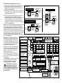
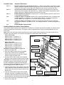
3. Secure the field common wire(s) and pump
start relay (or master valve) wire to the
appropriate terminals on the Pump/Com
module. See Figure 6.
4. Momentarily touch each valve control wire
to the Hot Post to activate and identify the
corresponding valve(s).
Figure 5
Pump Power
Source
Single Controller
Pump
Com
Starter
Power
Source
Multiple Controllers
Magnetic
Pump
Starter
To Other
Controllers
Relay
5. Secure the valve control wires to the staPump
24 V a.c.
Pump Power
tion terminals in the preferred order of
1A Max.
Source
Pump
Com
operating sequence. Station terminals are
Mag.
numbered left to right, 1–32 (front) and
Pump
Pump
Starter
33–64 (back). Each terminal can accomPressure Switch With
Starter
2
Controller
Override
Com
Power
modate two 14 gage (1.5mm ) solid copper
Relay Source
wires. See Figure 6.
Pressure Switch
Pump Power
24 V a.c.
Pump
Source
Note: A loop is provided on the plastic chas1A Max.
(Typical)
Magnetic
sis below each output module enabling a
Pump
wiring strain relief to be installed when the
Starter
Pump
Starter
optional standard terminal block connector
Power
Com
is used. After connecting the field wires,
Source
Relay
install a nylon cable tie through the loop and
24 V a.c.
1A Max.
Pump
around the wire bundle. Ensure the terminal
block is properly mated with the output
module connector after tightening the cable
tie. See Figure 6.
Note: The 3-position switches
Figure 6
Field Common
provided on the pump/com mod24 V a.c. Output
LED Indicator
Field Common
ule and the optional station terLED Indicators
Control Switch
minal board enable local control
(one per station)
of the field common, pump circuit
Field Common
and station output. The switch
LED Indicator
positions are as follows:
Pump Circuit
ON (up) – Manually activates the
LED Indicator
circuit. The pump, field common
3A Fuse
or station output will remain on
24 V.a.c. Output
(Station Output)
until the switch is moved to the
LED Indicator
(fuse condition)
AUTO or OFF position.
24 V a.c.
OFF (center) – Manually opens
Output LED
the circuit. Operation of the circuit
Indicator
will not occur while the switch is in
this position.
1A Fuse
24 V a.c.
(Pump Circuit)
AUTO (down) – Enables the circuit
Hot Post
to be automatically controlled
Pump Circuit
Standard
during automatic or manual
Control Switch
Terminal Block
(hand-held radio) operation.
Station Output
CAUTION: To prevent
damage to the station
output circuit fuse, do not
exceed 3 amp load when manually activating multiple station outputs.
Switches (optional)
Pump Output
LED Indicator
Field Common
Terminals (3)
Pump Relay
Terminal
Station Output
Terminals
Cable Tie
Strain Relief
4
(optional)