1
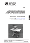
506-3
Instructions, complete
Operating Instructions
1
Installation Instructions
2
Service Instructions
3
Postfach 17 03 51, D-33703 Bielefeld • Potsdamer Straße 190, D-33719 Bielefeld
Telefon +49 (0) 521 / 9 25-00 • Telefax +49 (0) 521 / 9 25 24 35 • www.duerkopp-adler.com
Ausgabe / Edition:
10/2008
Änderungsindex
Rev. index: 01.0
Printed in Federal Republic of Germany
Teile-Nr./Part.-No.:
0791 506011
Instructions, complete
506-3
Overview
Operating table
Operating Instructions
Installation Instructions
Service Instructions
Pneumatic circuit plan
9770 506002
Interconnection-diagram
9890 506003 B
All rights reserved.
Property of Dürkopp Adler AG and copyrighted. Reproduction or publication of the content in any manner,
even in extracts, without prior written permission of Dürkopp Adler AG, is prohibited.
Copyright © Dürkopp Adler AG - 2008
Foreword
This instruction manual is intended to help the user to become familiar
with the machine and take advantage of its application possibilities in
accordance with the recommendations.
The instruction manual contains important information on how to
operate the machine securely, properly and economically. Observation
of the instructions eliminates danger, reduces costs for repair and
down-times, and increases the reliability and life of the machine.
The instruction manual is intended to complement existing national
accident prevention and environment protection regulations.
The instruction manual must always be available at the machine/sewing
unit.
The instruction manual must be read and applied by any person that is
authorized to work on the machine/sewing unit. This means:
–
–
–
Operation, including equipping, troubleshooting during the work
cycle, removing of fabric waste,
Service (maintenance, inspection, repair) and/or
Transport.
The user also has to assure that only authorized personnel work on the
machine.
The user is obliged to check the machine at least once per shift for
apparent damages and to immediatly report any changes (including the
performance in service), which impair the safety.
The user company must ensure that the machine is only operated in
perfect working order.
Never remove or disable any safety devices.
If safety devices need to be removed for equipping, repairing or
maintaining, the safety devices must be remounted directly after
completion of the maintenance and repair work.
Unauthorized modification of the machine rules out liability of the
manufacturer for damage resulting from this.
Observe all safety and danger recommendations on the machine/unit!
The yellow-and-black striped surfaces designate permanend danger
areas, eg danger of squashing, cutting, shearing or collision.
Besides the recommendations in this instruction manual also observe
the general safety and accident prevention regulations!
General safety instructions
The non-observance of the following safety instructions can cause
bodily injuries or damages to the machine.
1. The machine must only be commissioned in full knowledge of the
instruction book and operated by persons with appropriate training.
2. Before putting into service also read the safety rules and
instructions of the motor supplier.
3. The machine must be used only for the purpose intended. Use of
the machine without the safety devices is not permitted. Observe all
the relevant safety regulations.
4. When gauge parts are exchanged (e.g. needle, presser foot, needle
plate, feed dog and bobbin) when threading, when the workplace is
left, and during service work, the machine must be disconnected
from the mains by switching off the master switch or disconnecting
the mains plug.
5. Daily servicing work must be carried out only by appropriately
trained persons.
6. Repairs, conversion and special maintenance work must only be
carried out by technicians or persons with appropriate training.
7. For service or repair work on pneumatic systems, disconnect the
machine from the compressed air supply system (max. 7-10 bar).
Before disconnecting, reduce the pressure of the maintenance unit.
Exceptions to this are only adjustments and functions checks made
by appropriately trained technicians.
8. Work on the electrical equipment must be carried out only by
electricians or appropriately trained persons.
9. Work on parts and systems under electric current is not permitted,
except as specified in regulations DIN VDE 0105.
10. Conversion or changes to the machine must be authorized by us
and made only in adherence to all safety regulations.
11. For repairs, only replacement parts approved by us must be used.
12. Commissioning of the sewing head is prohibited until such time as
the entire sewing unit is found to comply with EC directives.
13. The line cord should be equipped with a country-specific mains
plug. This work must be carried out by appropriately trained
technicians (see paragraph 8).
It is absolutely necessary to respect the safety
instructions marked by these signs.
Danger of bodily injuries !
Please note also the general safety instructions.
Contents
Page:
Preface and General Safety Information
Part 1: Operating Instructions Cl. 506-3
(Edition 10/2008)
1.
1.1
1.2
1.3
Product Description
Description of the Proper Use and Proper Application . . . . . . . . . . . . . . . . . . . . . . . . .
Short Description . . . . . . . . . . . . . . . . . . . . . . . . . . . . . . . . . . . . . . . . . . . . . . .
Technical Data . . . . . . . . . . . . . . . . . . . . . . . . . . . . . . . . . . . . . . . . . . . . . . . .
2.
2.1
2.2
2.3
2.4
2.5
Operation
Automatic Sewing Sequence .
Needles and Yarns . . . . . . .
Threading the Needle Thread
Changing the Bobbin . . . . . .
Thread Tension . . . . . . . . .
.
.
.
.
.
9
11
12
14
16
3.
Bobbin winder . . . . . . . . . . . . . . . . . . . . . . . . . . . . . . . . . . . . . . . . . . . . . . . .
17
4.
4.1
4.2
Maintenance
Cleaning . . . . . . . . . . . . . . . . . . . . . . . . . . . . . . . . . . . . . . . . . . . . . . . . . . . .
Lubrication . . . . . . . . . . . . . . . . . . . . . . . . . . . . . . . . . . . . . . . . . . . . . . . . . . .
18
20
.
.
.
.
.
.
.
.
.
.
.
.
.
.
.
.
.
.
.
.
.
.
.
.
.
.
.
.
.
.
.
.
.
.
.
.
.
.
.
.
.
.
.
.
.
.
.
.
.
.
.
.
.
.
.
.
.
.
.
.
.
.
.
.
.
.
.
.
.
.
.
.
.
.
.
.
.
.
.
.
.
.
.
.
.
.
.
.
.
.
.
.
.
.
.
.
.
.
.
.
.
.
.
.
.
.
.
.
.
.
.
.
.
.
.
.
.
.
.
.
.
.
.
.
.
.
.
.
.
.
.
.
.
.
.
.
.
.
.
.
.
.
.
.
.
.
.
.
.
.
.
.
.
.
.
.
.
.
.
.
.
.
.
.
.
.
.
.
.
.
.
.
.
.
.
.
.
.
.
.
.
.
.
.
.
.
.
.
.
.
5
6
7
1
Noise level Lc
Workstation related emission according to DIN 45635-48-B-1
-1
Number of stitches:
1.000 min
Commanding cam:
(Stitches) 116
Sewing cycles:
9,7 s on / 2,0 s off
2
Sewing material:
2x girdle tape 1,5 mm 1.260 g/m
Measuring point to DIN 4895 Part 1
X = 0 mm
Y = -400 m
Z = 300 mm
Lc:
4
78 dB (A)
1. Product Description
1.1 Description of the Proper Use and Proper Application
The 506-3 is a robust, heavy-duty, curve-guided single needle
lockstitch short seam unit for seams of stitch type 301.
This short seam unit is designed for use in sewing heavy-weight fabric,
as well as thick and hard leather.
Thick and hard leathers find use in the sewing on of trim pieces, in the
sewing of buckle caps, tabs, suitcases, tarpaulins, knapsacks and
backpacks.
Heavy-weight fabrics are used in the sewing of heavy-duty carrying
belts, car belts, as well as belts for aviation.
Generally only dry sewing material may be worked with this machine.
The material may be no thicker than 16 mm when pressed together by
the lowered clamping feet.
The machine must be operated with eye protection. The information to
be found printed on the yellow sign on the head cover is to be strictly
adhered to.
The seam is generally made with synthetic sewing yarns with a
dimension of 30/3 to 8/3. Those wishing to use other threads must first
evaluate the dangers arising therefrom and, if necessary, take safety
measures.
This heavy short seam unit may only be installed and operated in dry
and clean areas. If the unit is used in other areas, which are not dry and
clean, further, to be agreed upon, measures may become necessary
(see EN 60204-31: 1999).
We, as manufacturer of industrial sewing machines, presume that the
operating personnel working on our products have been given
instruction so that all normal operations and the dangers possibly
arising therefrom can be assumed to be known.
5
1
1.2 Short Description
Uniform Quality
The unit always produces a uniform seam formation.
The high thread tension necessary for the working of heavy materials is
achieved through a hinged thread lever.
Direct Power Transmission
The power transmission from the motor to the arm shaft occurs via a
special V-belt. This results in a particularly strong perforating power for
the sewing of thick materials or multiple layers.
Interchangeable Curve Disks and Material Clamps
The different seam formations are determined by easily
interchangeable curve disks.
The material guidance occurs via a pattern curve with two guide curves.
The difficult and time-consuming turning of heavy pieces of material by
the seamstress is thus unnecessary.
The transmission of the movement to the material clamps occurs via
lever systems.
By changing the lever multiplication the seam formation sizes can be
varied within certain limits.
All curve disks belonging to a stitch number range are interchangeable
among each other.
Large Put-through Area and Large Placement Surface
The large put-through area allows the making of short seams far from
the edge of the material. A rolling-in of flexible sewing material is
possible. The closed width base plate offers a large placement surface
and simplifies the feed.
Pneumatic Clamp Opening
The stroke of the holder clamp is a maximum 20 mm. This stroke allows
the working of almost all sewable materials and leather thicknesses.
Electric Thread Burning Device
The thread separator device separates the needle and underthread by
burning immediately at the top edge of the material. The synthetic
threads are melted together at the ends. The thus created hardening
hinders a loosening of the seam and a unthreading of the needle thread.
Control Unit Quick DA104ED
The complete control of the sewing unit occurs via a Quick control unit.
It assumes the control tasks, monitors the sewing process and
indicates operator errors and malfunctions.
ATTENTION!
These operating instructions give the key functions and describe how
operator-level parameter values are changed by the operator.
For a detailed description of the control unit, please consult the enclosed
current issue of the operating manual of the motor manufacturer.
6
1.3 Technical Data
Sewing area:
Needle system:
maximum 60 x 100 mm
428; 428 Serv Nm 250;
794 (for thick sewing material only)
Needle thickness:
Nm 120 - Nm 280
depending on the type of sewing thread
and the sewing material.
Yarns:
Synthetic yarns
Nm 30/3 - 8/3
Bobbin capacity:
23 m with 18/3 yarn
Stitch type:
Lockstitch type 301
Number of stitches:
1100 / min
Number of stitches per
42, 58, 72 (without gear reducer)
guide curve revolution:
84, 116, 144 (with gear reducer)
Seam formation
72 stitches in 3.5 sec. or
144 stitches in 7 sec.
Looping stroke:
4 mm
Clamp stroke:
max. 20 mm
Sewing material thickness: max. 16 mm
(sewing material pressed
together by the clamp)
Power:
0.55 kW
Motor rpm:
max. 2800 rpm
Operating pressure:
6 bar
Air consumption:
approx. 1,2 NL per work cycle
Motor specifications:
Voltage:
1 x 230V, 50/60Hz
Power:
0,55 kW
Speed:
4000 rpm
Torque:
1.2 Nm
Dimensions:
(H x W x D) 1720 x 1100 x 736 mm
The listed height dimension applies to
the work height of the frame set at the
factory.
Put-through area:
210 x 140 mm
Work height:
760...1060 mm (upper edge of the table
top)
Weight:
160 kg
1
7
Notes:
8
2. Operation
2.1 Automatic Sewing Sequence
2
1
3
1
5
4
ATTENTION !
The starting of a sewing sequence is only possible with the head
cover 1 and cover 2 for the hook area closed.
If the head cover or cover for the hook area is open all functions of the
controls are blocked.
Work procedure (in foot switch mode 1)
– Turn the main switch 3 on.
The clamps are in their upper position.
– Select sewing program.
– Align the sewing material under the clamps.
Depending on the type of work sequence this can occur according
to the markings or the stops mounted specifically for the customer.
Caution Risk of Injury !
Keep hands free of the lowering clamps.
–
–
–
Operate the right foot switch 4.
Both clamps lower simultaneously.
Check the correct alignment of the sewing material.
To correct the sewing material alignment operate the right foot
switch again.
Both clamps rise.
Operate the left foot switch 5.
The automatic sewing sequence starts.
9
–
–
–
–
For a secure sewing-on pull the thread end hanging out of the
needle to the side when starting the first sewing sequence and hold
it tight.
After the first stitches the thread can be released again.
The automatic sewing sequence runs through according to the
selected sewing program.
For an exact description of the different sewing programs see
“Quick User’s manual”.
After the sewing sequence ends the clamps are raised
automatically.
Remove the sewing material.
Quick stop
1
3
2
The safety system of the 506-3 has two different options for the
immediate shut-off of the unit by operator error, needle breakage,
thread breakage etc.:
– Pressing the Stop key 1 on the front panel of the controls.
The sewing sequence is interrupted.
– Pressing the Stop key 2 on the head cover.
The sewing sequence is interrupted.
Bring the sewing machine to its starting position:
– Press button 3 on the sewing head.
The needle moves to its uppermost position.
– Press button 3 on the sewing head again.
The automatic sewing machine slowly returns to its starting
position.
10
2.2 Needles and Yarns
Needle system:
428; 428 Serv Nm 250; 794
(depending on the type of sewing thread and sewing
material used)
Needle thickness: Nm 120 - Nm 280
(depending on the type of sewing thread and sewing
material used)
Yarns:
Synthetic sewing yarns (30/3 to 8/3)
Changing the needle:
2
1
1
A
A
A-A
Caution Risk of Injury !
Turn the main switch off.
Change the needle only with the unit turned off.
–
–
–
–
–
Open the head cover.
Loosen screw 1.
Remove the needle.
Push the new needle into the hole in the needle bar up to the stop.
Hereby align the needle with the furrow 3 to the hook.
The furrow 2 must show to the front (to the seamstress).
Tighten screw 1.
Attention Danger of Breakage!
After a change to a needle with a different needle thickness it is
essential to check the clearances hook point-needle and
driver-needle.
If necessary reset the clearances (see Part 3: Service Instructions).
11
2.3 Threading the Needle Thread
Caution Risk of Injury !
Turn the main switch off.
Thread the needle thread only with the unit turned off.
The threading of the needle thread 18 occurs as shown in the pictures
alongside in increasing numerical order:
– Place the yarn roll on the yarn stand.
– Thread the thread through the holes 1 of the yarn stand.
– Thread the thread through thread guide 2.
– Lead the thread through between the tension disks of the first
needle thread tension 3.
– Thread the thread consecutively through thread guides 4 and 5.
– Guide the thread through between the tension disks of the second
needle thread tension 6.
– Thread the thread consecutively through the hole in the thread pull
7 and thread guide 8.
– Wind the thread from the bottom approx. two times around the
thread roller 9.
– Guide the thread through the thread controller spring 10.
– Guide the thread under the thread guide 12.
– Open the head cover.
– Thread the thread through the hole in the thread lever 13.
– Guide the thread through the hole in the thread control plate 14.
– Insert the thread from the side into the thread gripper 15.
– Thread the thread through the thread guide 17 on the needle bar.
– Thread the thread from the front to the back through the eye of the
needle.
1
18
12
12
11
10
9
8
7
6 5
4
3
2
1
13
14
15
16
17
13
2.4 Changing the Bobbin
3
2
1
4
Remove the bobbin
– Press button 2 on the sewing head or button “
” on the control
unit.
– Hold on to cover 1 and push the locking lever 3 upwards to unbolt
the cover.
– Fold cover 1 forward and down.
ATTENTION !
Cover 1 is monitored by a safety switch.
With the cover open, all functions of the controls are blocked.
Starting the sewing sequence after a change of bobbin is only possible
with the cover closed.
–
–
5
14
To swing the bobbin case 4 out press the ejector lever 5 to the left.
Remove the bobbin from the bobbin case 4.
10
6
9
8
7
1
Inserting a full bobbin
– Place the full bobbin in the bobbin case 6.
Here take care that when thread is being pulled off the bobbin must
turn clockwise (see the arrow direction)!
– Swing in the bobbin case 6.
– Pull the thread through the slit 10 into the opening 9 on the spring 8.
ATTENTION !
A thread sliding out of slit 10 can lead to missing stitches
and needle breakage.
Therefore pull the thread so far through slit 10 until it lies secure in the
opening 9 on the spring 8.
–
–
–
–
Insert the bobbin case.
Pull the thread out of the bobbin case.
Close cover 1.
Press “
” button.
–
The item counter is reset.
Start new sewing run.
15
2.5 Thread Tension
Set the thread tensions appropriate to the yarn types and
thicknesses used so that a clean seam formation results.
Too high thread tensions cause a crimping of the sewing material. Too
low a bobbin thread tension can lead to missing stitches.
Setting the needle thread tension
1
2
–
Set the upper needle thread tension by turning the knurled screw 1
and the lower needle thread tension by turning the knurled screw 2.
Setting the bobbin thread tension
3
4
–
–
–
16
Loosen the fastening screw 3.
Set the bobbin thread tension by turning the setting screw 4.
Tighten the fastening screw 3.
3. Bobbin winder
7
6
5
1
4
3
8
9
10
11
1
2
Reeling on the spool thread
– Place yarn reel on reel stand.
– Thread the thread through the holes 1 in the reel stand.
– Pass the thread through the tension discs of tensioner 2.
– Pass the thread through the tension discs of tensioner 3 of the reel.
– Pass the thread through the slot in guide 4.
– Pass the thread through the hole 7 in the empty reel.
– Place the empty reel on the bobbin shaft 8.
The pin 10 of the bobbin shaft must fit into the hole 7.
– Pass the thread through the star 10 and clamp it in the tensioner 11.
– Use the thread clipper 6 to cut off the end of the thread.
– Raise the thread layer 5.
The bobbin winder is switched on and the winding process begins.
– As soon as the reel is full the thread layer 5 springs back into
position and the winding process is terminated.
17
4. Maintenance
Caution Risk of Injury !
Turn the main switch off.
Maintenance work on the unit may only be conducted with the machine
turned off.
4.1 Cleaning
A clean machine protects against malfunctions !
Daily cleaning:
– Particularly the areas around the needle thread guides 1 and
tensions, thread controller spring and hook 2 are to be cleaned of
sewing dust and lint accumulations (e.g. with a compressed air
gun).
For cleaning the parts attached under the foundation plate tilt the
machine head aside.
2
1
18
–
Check the water level in the pressure regulator.
The water level should not be allowed to rise to the filter insert 3.
After screwing in the drain screw 5 blow the water out of the water
separator 4 under pressure.
Dirt and condensation water are eliminated through the filter insert 3.
Wash out the dirty filter bowl and filter insert with naphtha after a
certain period of operation and blow clean with compressed air.
ATTENTION !
Do not use solvents for washing!
They destroy the filter bowl.
1
3
4
5
Cleaning as required:
–
–
Empty sump pan 1 of the central recirculating-lubrication unit.
Empty collection bag 2 of the thread-suction device and remove any
accumulations of fluff (e.g. with a compressed air gun).
2
1
19
4.2 Lubrication
For lubrication of the machine use only DA-10 lubricating oil.
DA-10 is available from DÜRKOPP ADLER AG retail outlets.
Check the oil level in the oil reservoir of the oil mister
The run of the barrel shuttle is lubricated and cooled by compressed air
enhanced with oil from the oil mister.
– The oil level in oil reservoir 5 must not fall below the suction tube 4.
– If necessary, top up with oil to the upper edge of the embossed
text 3.
– For topping up screw out the oil filler screw 2.
1
2
3
4
5
Check the feed quantity of the oil mister weekly
– Under operating pressure a drop of oil should drip out of the pipe
under the viewing glass 5 after every 2 to 3 work cycles.
– Regulate the strength of the thus created oil mist at the setting
screw 1.
20
Checking the oil level in the oil reservoir of the central lubrication
unit
The central recirculating-lubrication unit automatically supplies all the
automatic sewing machine’s important lubrication points.
– The oil level in oil reservoir 1 must not fall below the “min” mark.
– If necessary, top up with oil to the “max” mark.
1
1
21
Notes:
22