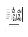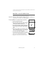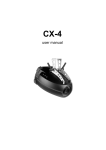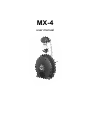
1
MX-4
user manual
1
focus lens
2
cover bolts
3
air vent
4
mirror assembly
5
pan/tilt arm
6
safety cable holes
7
mounting bracket
8
air vents
9
AC input & main
fuse
10 DIP-switch
11 lamp access plate
12 data sockets
13 swivel locks
14 cooling fan
©1999 - 2000 Martin Professional A/S, Denmark.
All rights reserved. No part of this manual may be
reproduced, in any form or by any means, without
permission in writing from Martin Professional A/S,
Denmark.
Printed in Denmark.
P/N 35000086, Rev. E
2
INTRODUCTION . . . . . . . . . . . . . . . . . . . . . . . . . . . . . . . . . . . . . . . 4
AC POWER . . . . . . . . . . . . . . . . . . . . . . . . . . . . . . . . . . . . . . . . . . 6
INSTALLATION . . . . . . . . . . . . . . . . . . . . . . . . . . . . . . . . . . . . . . . . 9
STAND-ALONE OPERATION. . . . . . . . . . . . . . . . . . . . . . . . . . . . . . 10
MC-1 OPERATION . . . . . . . . . . . . . . . . . . . . . . . . . . . . . . . . . . . . 12
DMX OPERATION . . . . . . . . . . . . . . . . . . . . . . . . . . . . . . . . . . . . 13
LAMP . . . . . . . . . . . . . . . . . . . . . . . . . . . . . . . . . . . . . . . . . . . . . 18
BASIC SERVICE . . . . . . . . . . . . . . . . . . . . . . . . . . . . . . . . . . . . . . 20
TROUBLESHOOTING. . . . . . . . . . . . . . . . . . . . . . . . . . . . . . . . . . . 22
DMX PROTOCOL . . . . . . . . . . . . . . . . . . . . . . . . . . . . . . . . . . . . . 23
SPECIFICATIONS . . . . . . . . . . . . . . . . . . . . . . . . . . . . . . . . . . . . . 25
3
1
INTRODUCTION
Thank you for selecting the Martin MX-4. This automated moving-mirror spotlight
provides 15 full and 2 split colors, 19 gobos, high-speed shutter, 230° of pan and
76° of tilt, adjustable focus, and a 16° beam angle. It uses a 150 watt discharge lamp
and may be operated with DMX controllers, the Martin MC-1 remote control, or as
a stand-alone unit with master/slave capability.
SAFETY INFORMATION
Warning!
This product is for professional use only. It is not for household
use.
This product presents risks of lethal or severe injury due to fire and heat, electric
shock, ultraviolet radiation, lamp explosion, and falls. Read this manual before
powering or installing the fixture, follow the safety precautions listed below and
observe all warnings in this manual and on the fixture. If you have questions about
how to operate the fixture safely, please contact your Martin dealer or call the
Martin 24-hour service hot line.
To protect yoursel f and others fr om electric shock
• Disconnect the fixture from AC power before removing or installing the lamp,
fuses, or any part, and when not in use.
• Always ground (earth) the fixture electrically.
• Use only a source of AC power that complies with local building and electrical
codes and has both overload and ground-fault protection.
• Do not expose the fixture to rain or moisture.
• Refer all service to a Martin service technician.
To protect yoursel f and others fr om UV radiation and lamp
explosion
• Never operate the fixture with missing or damaged lenses and/or covers.
• When replacing the lamp, allow the fixture to cool for at least 5 minutes before
opening the fixture or removing the lamp. Protect your hands and eyes with gloves
and safety glasses.
4
Introduction
• Do not stare directly into the light. Never look at an exposed lamp while it is lit.
• Replace the lamp if it becomes defective or worn out.
To protect yourself and other s from burns and fire
• Never attempt to bypass the thermostatic switch or fuses. Always replace defective
fuses with ones of the specified type and rating.
• Keep all combustible materials (for example fabric, wood, paper) at least 0.1 meters
(4 inches) away from the fixture. Keep flammable materials well away from the
fixture.
• Do not illuminate surfaces within 0.3 meters (12 inches) of the fixture.
• Provide a minimum clearance of 0.1 meters (4 inches) around fans and air vents.
• Never place filters or other materials over the lens or mirror.
• Allow the fixture to cool before handling.
• Do not modify the fixture or install other than genuine Martin parts.
• Do not operate the fixture if the ambient temperature (Ta) exceeds 40° C (104° F).
To protect yourself and other s from injury due to fall s
• When suspending the fixture above ground level, verify that the structure can hold
at least 10 times the weight of all installed devices.
• Verify that all external covers and rigging hardware are securely fastened and use an
approved means of secondary attachment such as a safety cable.
• Block access below the work area whenever installing or removing the fixture.
UNPACKING
The packing material is carefully designed to protect the fixture during shipment always use it to transport the fixture.
The MX-4 comes with:
• Philips CDM-SA/T 150W discharge lamp
• 3 m, 3-pin IEC mains cable
• user manual
Introduction
5
2
AC POWER
The MX-4 power supply has 5 voltage and 2 frequency settings. The factory default
setting is shown on the serial number label.
Warning!
For protection from fire and electric shock, the fixture must be
grounded (earthed). The power supply shall have overload and
ground-fault protection.
Warning!
Verify that the feed cables are undamaged and rated for the
current requirements of all connected devices before use.
Important! Check the power supply setting before applying power.
Important! The mirror assembly is secured for transport with a plastic tie.
Cut and remove the tie before applying power.
Important! Do not connect the fixture to a dimmer system.
To install a plug on the mains lead
The mains lead must be fitted with a grounding-type cord cap that fits your
power distribution system. Consult a qualified electrician if you have any
doubts about proper installation.
•
Following the cord cap manufacturer’s instructions, connect the yellow and
green wire to ground (earth), the brown wire to live, and the blue wire to neutral.
The table below shows some pin identification schemes.
Wire
Pin
Marking
Screw color
brown
live
“L”
yellow or brass
blue
neutral
“N”
silver
yellow/green
ground
Table 1: Cord cap wiring
6
AC power
green
To rewire the power supply
Always use the setting that most closely matches the local AC mains voltage and
frequency.
1 Disconnect the fixture from AC power. Remove the top cover bolts with a 4 mm
Allen wrench and lift off the cover.
2 On the transformer, which is located behind the color wheel, move the brown
and white wires to the transformer taps shown for your mains voltage. (If your
MX-4 has 2 blue wires, the blue wire with the insulated spade plug corresponds
to the white wire.)
Important! Do not move the blue wire from terminal 9 or the black wire from
terminal 15.
Mains voltage
Setting
Brown
White
95 - 109 V
100 V
12
10
110 - 130 V
120 V
12
9
200 - 219 V
210 V
15
10
219 - 239 V
230 V
15
9
240 - 260 V
250 V
16
9
Table 2: Transformer settings
1 2 3 4 5 6 7 8
orange
orange
blue
white
black
brown
9 10 11 12 13 14 15 16
9 10 11 12 13 14 15 16
1 2 3 4 5 6 7 8
1 2 3 4 5 6 7 8
orange
orange
blue
white
black
brown
230 V
210 V
orange
orange
blue
white
black
brown
120 V
100 V
orange
orange
blue
white
black
brown
1 2 3 4 5 6 7 8
9 10 11 12 13 14 15 16
9 10 11 12 13 14 15 16
AC power
7
1 2 3 4 5 6 7 8
250 V
orange
orange
blue
white
black
brown
9 10 11 12 13 14 15 16
3 To set the frequency, move the black wire on the ballast to the “230-50” (50 Hz)
or “230-60” (60 Hz) terminal as shown. The wire is released and locked by
inserting a small screwdriver in the square hole next to the terminal and prying
back the spring.
4 Tug lightly on the black wire to make sure that it is connected securely.
5 Replace the top cover.
50 Hz
60 Hz
black
brown
8
black
brown
AC power
3
I NSTALLATION
The MX-4 can be fastened directly to a suitable surface or to a rigging clamp by
means of its adjustable mounting bracket. It can also be placed at an angle directly
on the stage or floor using the mounting bracket as a floor stand. Do not lay the
fixture flat on its pan/tilt arms: this can cause the fixture to overheat.
If using the GE Arcstream lamp, see “To orient the Arcstream lamp for maximum
life” on page 19.
Warning!
Block access below the work area before proceeding.
Warning!
Always use a secure means of secondary attachment.
To rig the MX-4
1 If using a rigging clamp (not included), verify that it is undamaged and can bear
at least 10 times the fixture’s weight. Bolt the clamp securely to the bracket
with a grade 8.8 (minimum) M12 bolt and lock nut, or as recommended by the
clamp manufacturer, through the 13 mm hole in the center of the mounting
bracket.
2 If fastening the fixture directly, verify that the hardware (not included) and
mounting surface can bear at least 10 times the fixture’s weight. The four 6.2
mm holes and/or the 13 mm hole in the mounting bracket may be used.
3 Verify that the structure can support at least 10 times the weight of all installed
fixtures, clamps, cables, auxiliary equipment, etc.
4 Working from a stable platform, clamp or fasten the fixture to the structure.
5 Install a safety cable that can hold at least 10 times the weight of the fixture
through/over the support and through a hole in the pan/tilt arm.
6 Loosen the swivel locks and tilt the fixture to the desired angle. Turn the swivel
locks clockwise to tighten. If a swivel lock does not tighten fully, pull the handle
out, turn it counterclockwise, and retighten. Repeat as necessary.
7 Verify that the fixture is located at least 0.3 meters (12 in.) away from the
surface to be illuminated and at least 0.1 meters (4 in.) from any combustible
materials. Verify that the clearance around the fan and air vents is at least 0.1
meters (4 in.). Verify that there are no flammable materials nearby.
Installation
9
4
STAND-ALONE OPERATION
CUSTOM SETTINGS
Stand-alone operation may be customized with the settings in Table 3. The options
may be combined and are set using DIP-switch pins 1 - 10. Changes may not take
effect until after the fixture has been turned off and on.
Mode
Effect
Pin setting (0 = OFF, 1 = ON)
1
single / master
auto trigger
0
music trigger
1
slow pan/tilt
2
3
1
0
4
5
1
wide pan/tilt
inverted gobo
inverted tilt
7
8
9
10
0
0
0
0
1
1
inverted color
slave
6
1
0
0
0
0
0
inverted pan
1
1
1
1
Table 3: Custom stand-alone settings
SINGLE FIXTURE OPERATION
When there is no control signal at the data input for 5 seconds, the MX-4
automatically goes into stand-alone mode regardless of the DIP-switch setting. It
uses music trigger unless stand-alone mode is enabled and auto trigger is selected.
To operate 1 fixture in stand-al one mode
1 Disconnect the fixture from power and data.
2 (Optional) Set DIP-switch pins 2 and 10 to ON. Set pin 3 to OFF. Select standalone options as listed in Table 3.
3 Apply power.
When you apply power, the option settings take effect and the lamp strikes. Note: A
hot lamp must cool for several minutes before it can be restruck. If the lamp does
10
Stand-alone operation
not strike, disconnect the fixture from power for several minutes to reduce strain on
the starter while the lamp cools.
MASTER / SLAVE OPERATION
Up to 32 MX-4s can be connected together and operated in master/slave mode in
which slave fixtures follow instructions sent from the master.
Important! Set only 1 fixture as master: damage can occur if 2 masters, or
a master and a controller, are linked together.
To set up MX-4s for master/slave oper ation
1 Disconnect all fixtures from power.
Female
Termination Plug
2 Plug a data cable into the OUT socket of the first
Female XLR
fixture and the IN socket of the next one. Continue
1
2
3
connecting up to 32 MX-4s output-to-input.
3 Insert a female termination plug (P/N 91613018) in the
120
IN socket of the first fixture. Insert a male termination
plug (see page 13) in the OUT socket of the last
fixture.
P/N 91613018
4 Select any one fixture to be the master. On this
custom master options with pins 1, 4, and 5. Set pins
ON
fixture, set DIP-switch pins 2 and 10 to ON. Set
3, 6, 7, 8, 9, 11, and 12 to the OFF position.
1 2 3 4 5 6 7 8 9 10 11 12
Master setting
5 On all other fixtures (slaves), set DIP-switch 10 to ON.
pins 1, 2, 3, 4, 5, 11, and 12 to the OFF position.
6 Apply power to the master fixture before the slaves.
Stand-alone operation
ON
Set custom slave options with pins 6, 7, 8, and 9. Set
1 2 3 4 5 6 7 8 9 10 11 12
Slave setting
11
5
MC-1 OPERATION
The MX-4 is fully compatible with the Martin MC-1 Controller. See the MC-1 user
manual for additional information.
SETTINGS
DIP-switch pin 10 must be set to OFF to enable MC-1 mode operation. Changes to
the setting take effect after the fixture has been turned off and on.
DIP-switch pins 5, 6, 7, 8, and 9 select several control options that can be combined
to achieve powerful effects quickly and easily.
Option
Setting (0 = OFF, 1 = ON)
1
2
3
wide pan/tilt
5
6
7
8
9
1
inverted color
0
1
inverted tilt
0
1
inverted pan
0
1
MC-1 operation
10
0
1
inverted gobo
12
4
0
11
6
DMX OPERATION
This section describes how to set up and connect the MX-4 for operation with DMX
controllers.
DATA CONNECTION
A reliable data connection begins with the right cable. Standard microphone cable
cannot transmit DMX data reliably over long runs. For best results, use cable
specifically designed for RS-485 applications. Your Martin dealer can supply high
quality cable in various lengths.
CONNECTIONS
The MX-4’s XLR data sockets are wired with pin 1 to ground, pin 2 to signal (cold), and pin 3 to signal + (hot). This is the standard pin assignment for DMX
devices.
One or more adaptor cables may be required to connect the MX-4 to the controller
and/or other lights because many devices have 5-pin connectors and others may
have reversed signal polarity, that is, pin 2 hot and pin 3 cold.
5-pin to 3-pin
Adaptor
3-pin to 5-pin
Adaptor
Male
Female
Male
Female
Male
Female
1
2
3
4
5
1
2
3
1
2
3
1
2
3
4
5
1
2
3
1
2
3
P/N 11820005
P/N 11820004
3-pin to 3-pin
Phase-Reversing
Adaptor
P/N 11820006
DMX operation
Male
Termination Plug
Male XLR
1
2
3
120
P/N 91613017
13
To connect the data link
1 Connect a data cable to the controller’s data output. If the controller has a 5-pin
output, use a 5-pin male to 3-pin female adaptor cable (P/N 11820005).
2 Lead the data cable from the controller to the first fixture and plug it into the
data input.
3 Connect the output of the fixture closest to the controller to the input of the
next fixture. If connecting to a fixture with reversed-polarity (pin 3 cold), insert
a phase-reversing cable between the two fixtures.
4 Continue connecting fixtures output to input. Up to 32 devices may be
connected on a serial link.
5 Terminate the link by inserting a male termination plug (P/N 91613017) into the
data output of the last fixture. A termination plug is simply an XLR connector
with a 120 ohm, 0.25 W resistor soldered across pins 2 and 3.
1-CHANNEL DMX OPERATION
The 1-channel DMX mode provides simple remote activation of the MX-4’s standalone programs plus blackout and strobe functions. The 1-channel functions are
shown in Table 5. Each fixture runs its own program and therefore cannot be
synchronized with other fixtures.
DMX value
Percent
Function
0 - 10
11 - 20
21 - 80
81 - 115
116 - 140
141 - 175
176 - 210
211 - 255
0-4
5-7
8 - 31
32 - 45
46 - 55
56 - 68
69 - 82
83 - 100
Blackout (light off)
Shutter open (light on)
Strobe
Stand-alone action with slow music trigger
Stand-alone action with medium music trigger
Stand-alone action with fast music trigger
Stand-alone action with random music trigger
Manual trigger area, crossover at 240 (94%)
Table 4: 1-channel DMX functions
14
DMX operation
6/7 CHANNEL DMX OPERATION
The 6-channel DMX mode provides position control of all effects plus speed
control of the moving mirror. The optional 7-channel mode adds speed control of
the color and gobo wheels.
Lamp power
Lamp power can be switched on and off from the controller. When set up for 6- or
7-channel DMX operation, the lamp remains off until a lamp-on command is sent.
Note: A peak of electric current many times the operating current is drawn briefly
when striking a lamp. Striking many discharge lamps at once may cause a voltage
drop that prevents lamps from striking or trips circuit breakers. When striking
multiple fixtures, space lamp-on commands at 5 second intervals.
A hot lamp must be allowed to cool for several minutes before it can be turned back
on. To prevent accidental lamp-off commands, a lamp-off can be executed only
when channel 2 and 3 are set to full.
If a hot lamp does not strike, send the lamp-off command and wait several minutes
before trying again.
Reset
All effects can be reset to their index positions from the controller. The reset
command must be sent for 5 seconds before it takes effect.
Shutter
The shutter opens, closes, and strobes at variable rates from 1.5 to 13.5 Hz.
Stand-alone
When stand-alone with music or auto trigger is selected on channel 1, the mirror
moves to random positions using the selected trigger. The color and gobo wheels
can be controlled normally, or, by setting their control channels to full, they can be
set to operate in stand-alone mode as well.
Colors
The color wheel provides 15 full-color filters, 2 split-color filters, and an open
position. The wheel may be positioned between 2 positions for additional splitcolor effects. Movement speed can be controlled on channel 7, if enabled.
For stand-alone color action, set channel 2 to a value from 210 to 255 and set
channel 1 to stand-alone with music or auto trigger.
Gobos
The gobo wheel provides 19 gobos and an open position. Movement speed can be
controlled on channel 7, if enabled.
For stand-alone gobo action, set channel 3 to a value from 240 to 255 and set
channel 1 to stand-alone with music or auto trigger.
Pan and tilt
The mirror pans 230° and tilts 76.5°. Movement speed is controlled on channel 6,
allowing you to program fades on controllers without cross-fader. If your controller
has cross-faders, and you use them, set channel 6 to the “tracking” speed for best
results.
DMX operation
15
To select DMX mode
1 Disconnect the fixture from power. Set DIP-switch pin 10 to OFF.
2 To select 1-channel DMX mode, set DIP-switch pin 11 to ON.
3 To select 6-channel DMX mode, set DIP-switch pin 11 to OFF. Verify that the 6/7
ch. jumper is set for 6 channels. This is the factory configuration. See “Setting
the 6/7-ch. DMX jumper” on page 21.
4 To select 7-channel DMX mode, set DIP-switch pin 11 to OFF. Set the 6/7 ch.
jumper for 7 channels as described on page 21.
DMX ADDRESS
The DMX address, also known as the start channel, is the first channel used to
receive instructions from the controller. It is set using the DIP-switch.
For independent control, each fixture must be assigned its own address and nonoverlapping control channels. Two MX-4s may share the same address only if they
are to respond identically: they will receive the same instructions and individual
control will not be possible.
Pin 12 is reserved for future use and currently has no function.
To set the DMX address
1 Select a DMX mode as described above.
2 Select a DMX address for the fixture on your controller.
3 Look up the DIP-switch setting for the address in Table 5.
4 Set pins 1 through 9 to the ON (1) or OFF (0) position as listed in the table.
16
DMX operation
DIP-Switch Setting
#1
0
1
0
1
0
1
0
1
0
1
0
1
0
1
0
1
0
1
0
1
0
1
0
1
0
1
0
1
0
1
0
1
0 = OFF
1 = ON
#2 #3 #4
0
0
0
0
0
0
1
0
0
1
0
0
0
1
0
0
1
0
1
1
0
1
1
0
0
0
1
0
0
1
1
0
1
1
0
1
0
1
1
0
1
1
1
1
1
1
1
1
0
0
0
0
0
0
1
0
0
1
0
0
0
1
0
0
1
0
1
1
0
1
1
0
0
0
1
0
0
1
1
0
1
1
0
1
0
1
1
0
1
1
1
1
1
1
1
1
#5
0
0
0
0
0
0
0
0
0
0
0
0
0
0
0
0
1
1
1
1
1
1
1
1
1
1
1
1
1
1
1
1
#9
#8
#7
#6
0
0
0
0
0
0
0
1
0
0
1
0
0
0
1
1
0
1
0
0
0
1
0
1
0
1
1
0
0
1
1
1
1
0
0
0
1
0
0
1
1
0
1
0
1
0
1
1
1
1
0
0
1
1
0
1
1
1
1
0
1
1
1
1
1
2
3
4
5
6
7
8
9
10
11
12
13
14
15
16
17
18
19
20
21
22
23
24
25
26
27
28
29
30
31
32
33
34
35
36
37
38
39
40
41
42
43
44
45
46
47
48
49
50
51
52
53
54
55
56
57
58
59
60
61
62
63
64
65
66
67
68
69
70
71
72
73
74
75
76
77
78
79
80
81
82
83
84
85
86
87
88
89
90
91
92
93
94
95
96
97
98
99
100
101
102
103
104
105
106
107
108
109
110
111
112
113
114
115
116
117
118
119
120
121
122
123
124
125
126
127
128
129
130
131
132
133
134
135
136
137
138
139
140
141
142
143
144
145
146
147
148
149
150
151
152
153
154
155
156
157
158
159
160
161
162
163
164
165
166
167
168
169
170
171
172
173
174
175
176
177
178
179
180
181
182
183
184
185
186
187
188
189
190
191
192
193
194
195
196
197
198
199
200
201
202
203
204
205
206
207
208
209
210
211
212
213
214
215
216
217
218
219
220
221
222
223
224
225
226
227
228
229
230
231
232
233
234
235
236
237
238
239
240
241
242
243
244
245
246
247
248
249
250
251
252
253
254
255
256
257
258
259
260
261
262
263
264
265
266
267
268
269
270
271
272
273
274
275
276
277
278
279
280
281
282
283
284
285
286
287
288
289
290
291
292
293
294
295
296
297
298
299
300
301
302
303
304
305
306
307
308
309
310
311
312
313
314
315
316
317
318
319
320
321
322
323
324
325
326
327
328
329
330
331
332
333
334
335
336
337
338
339
340
341
342
343
344
345
346
347
348
349
350
351
352
353
354
355
356
357
358
359
360
361
362
363
364
365
366
367
368
369
370
371
372
373
374
375
376
377
378
379
380
381
382
383
384
385
386
387
388
389
390
391
392
393
394
395
396
397
398
399
400
401
402
403
404
405
406
407
408
409
410
411
412
413
414
415
416
417
418
419
420
421
422
423
424
425
426
427
428
429
430
431
432
433
434
435
436
437
438
439
440
441
442
443
444
445
446
447
448
449
450
451
452
453
454
455
456
457
458
459
460
461
462
463
464
465
466
467
468
469
470
471
472
473
474
475
476
477
478
479
480
481
482
483
484
485
486
487
488
489
490
491
492
493
494
495
496
497
498
499
500
501
502
503
504
505
506
507
508
509
510
511
Table 5: DIP-switch address settings
DMX operation
17
7
LAMP
COMPATIBLE LAMPS
The MX-4 uses the Philips CDM-SA/T (short-arc, tubular) 150W discharge lamp.
If desired, the GE Arcstream 150 may be substituted. Installing any other lamp may
damage the fixture.
To replace the lamp
WARNING! Wear safety glasses and allow the lamp to cool for at least 5
minutes before removing the lamp.
1 Disconnect the fixture from power and allow it to cool.
2 Remove 2 screws from the lamp-socket assembly with a Pozidriv #2
screwdriver. Remove the lamp assembly.
3 Remove the old lamp from the socket.
4 Holding the new lamp by its base (do not touch the glass), insert the lamp pins
squarely into the socket.
5 If your fingers touched the glass bulb, clean it with a clean, lint-free cloth
wetted with alcohol.
6 Insert the lamp assembly carefully so that the lamp wires are clear of the fan.
Replace the screws.
To ali gn the l amp
Realignment when changing the lamp may improve performance.
1 Strike the lamp and shine the light on a flat surface.
2 Center the hot-spot (the brightest part of the beam) horizontally with small
turns of the top-left adjustment screw using a 3 mm Allen wrench.
3 Center the hot-spot vertically with the bottom adjustment screw.
4 If there is no hot-spot, adjust the reflector until the light is even.
18
Lamp
To orient the Arcstream lamp for maximum l ife
If using the GE Arcstream lamp, maximum lamp life will be achieved by installing
the lamp so that the arc is parallel with the ground.
This is the case in most installations. If the fixture is installed sideways, however, as
shown to the right, below, the arc will be vertical. Turn the lamp socket 90° to
achieve the ideal burning position.
1 Disconnect the fixture from power and allow it to cool.
2 Remove 2 screws from the lamp-socket assembly with a Pozidriv #2
screwdriver. Remove the lamp assembly.
3 Remove 2 screws from the lamp socket with a Pozidriv #1 screwdriver.
4 Turn the socket 90°, as shown below, in the direction that results in the least
amount of twist in the wires. Tuck the lamp wires into the notches in the socket
and replace the screws.
5 Insert the lamp assembly carefully so that the lamp wires are clear of the fan
and replace the access-plate screws.
6 Align the lamp as described above.
Lamp
19
BASIC
8
SERVICE
The MX-4 requires simple routine maintenance. The maintenance schedule
depends heavily on the operating environment; please consult a Martin service
technician for recommendations.
Any service procedure not described here should be referred to a qualified
technician.
Important! Excessive dust, grease, and smoke fluid buildup degrades
performance and causes overheating and damage to the fixture
that is not covered by the warranty.
Warning!
Disconnect the fixture from AC power before removing any
cover.
CLEANING
To clean opti cal components
Use care when cleaning optical components. The surface of the color filters is
fragile and small scratches may be visible.
1 Disconnect the fixture from AC power and allow the components to cool
completely.
2 Remove the top cover bolts with a 4 mm Allen wrench and lift off the cover.
3 Blow or vacuum away loose dust. Remove residues from lenses and filters with
a soft cloth or cotton swabs wetted with isopropyl alcohol. Regular glass
cleaner may also be used, but no residues may remain.
4 Rinse with distilled water. Mixing the water with a small amount of wetting
agent such as Kodak Photoflo will help prevent streaking and spotting.
5 Dry with a clean, soft and lint-free cloth or blow dry with compressed air.
6 Replace the top cover.
20
Basic service
To cl ean the fan and air vents
To maintain adequate cooling, dust must be cleaned from the fan and air vents
periodically.
1 Remove the data and power cables and stand the fixture on end.
2 Remove dust and dirt from the fan blades and vent grills using a soft brush,
cotton swab, vacuum, or compressed air.
REPLACING FUSES
The MX-4 has 2 fuses. The main fuse holder is built in to the mains input socket.
The secondary fuse is located on the printed circuit board.
Warning!
Never replace fuses with ones of a different rating!
To replace the main fuse
1 Unplug the mains cable from the input socket. Pry open the fuse holder and
remove the fuse.
2 Replace the fuse with one of the same type. The fuse rating is listed on serial
number label.
To replace the secondary fuse
1 Disconnect the fixture from AC power. Remove the top cover bolts with a 4 mm
Allen wrench and lift off the cover.
2 The fuse is located right behind the data input connector. Pry out the defective
fuse and replace it with one of the same rating.
3 Replace the cover before applying power.
SETTING THE 6/7-CH. DMX JUMPER
1 Disconnect the fixture from power.
2 Remove the top cover. Locate PL 118 on the printed circuit board, next to DIPswitch pin 12.
3 Using a pair of tweezers or similar tool, place the jumper on 1 of the 2 pins, or
remove it completely, for 6-channel DMX operation. Place the jumper on both
pins to enable 7-channel DMX operation.
4 Replace the top cover before applying power.
Basic service
21
9
TROUBLESHOOTING
Problem
One or more of the fixtures is
completely dead.
Fixtures reset correctly but all
respond erratically or not at all
to the controller.
Fixtures reset correctly but
some respond erratically or not
at all to the controller.
Remedy
No power to fixture.
Check that power is switched on
and cables are plugged in.
Primary fuse blown.
Replace fuse.
Secondary fuse blown.
Replace fuse.
The controller is not connected.
Connect controller.
XLR pin-out of the controller
does not match pin-out of the
first fixture on the link (i.e.
signal is reversed).
Install a phase-reversing cable
between the controller and the
first fixture on the link.
Bad data link connection
Inspect connections and cables.
Correct poor connections.
Repair or replace damaged
cables.
Data link not terminated with
120Ω termination plug.
Insert termination plug in output
jack of the last fixture on the
link.
Incorrect addressing of the
fixtures.
Check DIP-switch settings.
One of the fixtures is
transmitting as a master or is
defective.
Bypass one fixture at a time
until normal operation is
regained: unplug both
connectors and connect them
directly together. Have the
defective fixture serviced by a
qualified technician.
An effect fails to reset correctly.
The effect requires mechanical
adjustment.
Contact Martin technician for
service.
No light.
Lamp missing or blown
Disconnect fixture and replace
lamp.
Fixture is too hot.
Allow fixture to cool.
The transformer setting does not
match local AC voltage.
Check AC setting.
Lamp cuts out intermittently or
burns out too quickly.
22
Probable cause(s)
Troubleshooting
A
DMX PROTOCOL
Channel
1
2
Value
Percent
Function
0-9
10 - 19
20 - 99
100 - 159
160 - 179
180 - 204
205 - 229
230 - 239
240 - 249
250 - 255
0-3
3-7
7 - 39
39 - 62
63 - 70
70 - 80
80 - 90
90 - 94
94 - 98
98 - 100
Shutter, Lamp power, Reset
Shutter closed (blackout)
Lamp-on
Shutter open
Strobe, fast to slow
Shutter closed
Remote stand-alone w/ music trigger
Remote stand-alone w/ auto trigger
Shutter closed
Reset (hold for 5 sec.)
Lamp-off (w/ ch. 2 & 3 > 252, hold for 5 sec.)
0-5
6 - 11
12 - 17
18 - 23
24 - 29
30 - 35
36 - 41
42 - 47
48 - 53
54 - 59
60 - 65
66 - 71
72 - 77
78 - 83
84 - 89
90 - 95
96 - 101
102 - 107
108 - 113
114 - 119
120 - 125
126 - 131
132 - 137
138 - 143
144 - 149
150 - 155
156 - 161
162 - 167
168 - 173
174 - 179
180 - 185
186 - 191
192 - 197
198 - 203
204 - 209
210 - 255
0-1
2-4
4-6
7-9
9-11
11-13
14-16
16-18
18-20
21-23
23-25
26-27
28-30
30-32
33-35
35-37
37-39
40-42
42-44
44-46
47-49
49-51
52-53
54-56
56-58
59-61
61-63
63-65
66-68
68-70
70-72
73-75
75-77
78-79
80-82
82-100
Color wheel
White
White / Light blue 101
Light blue 101
Light blue 101 / Fern green 205
Fern green 205
Fern green 205 / Red 304
Red 304
Red 304 / Yellow 603
Yellow 603
Yellow 603 / Magenta 507
Magenta 507
Magenta 507 / Medium blue 108
Medium blue 108
Medium blue 108 / Deep orange 302
Deep orange 302
Deep orange 302 / Light green 204
Light green 204
Light green 204 / Cyan 104
Cyan 104
Cyan 104 / Pink 312
Pink 312
Pink 312 / Blue 111
Blue 111
Blue 111 / Amber 604
Amber 604
Amber 604 / Primary red 308
Primary red 308
Primary red 308 / Primary green 206
Primary green 206
Primary green 206 / Orange 306
Orange 306
Orange 306 / Split-color 1
Split-color 1
Split-color 1 / Split-color 2
Split-color 2
Remote stand-alone action, select trigger on ch. 1
DMX protocol
23
Channel
Value
Percent
Function
0 - 11
12 - 23
24 - 35
36 - 47
48 - 59
60 - 71
72 - 83
84 - 95
96 - 107
108 - 119
120 - 131
132 - 143
144 - 155
156 - 167
168 - 179
180 - 191
192 - 203
204 - 215
216 - 227
228 - 239
240 - 255
0-4
5-8
9 - 13
14 - 18
19 - 23
24 - 27
28 - 32
33 - 37
38 - 41
42 - 46
47 - 51
52 - 55
56 - 60
61 - 65
66 - 70
71 - 74
75 - 79
80 - 84
85 - 88
89 - 96
97 - 100
Gobo Wheel
Open
Worms 2
Web
Petals
Spokes
Cone 2
Maze
Crater
Holes 2
Cross 2
Jagged cross
Atomic
Dot circle
Nordic
Aim
Spokes 2
Tie
Nova
Triple beam
Dot 2
Remote stand-alone action, select trigger on ch. 1
4
0 - 255
0 - 100
Pan
Left to right (127 = neutral)
5
0 - 255
0 - 100
Tilt
Up to down (127 = neutral)
6
0-2
3 - 255
0-1
2 - 100
Pan/Tilt Speed
Tracking (speed function off)
Fast to slow
7*
0 - 255
0 - 100
Color / Gobo Speed (extended mode - jumper on PL118)
Fast to slow
3
24
DMX protocol
B
S PECIFICATIONS
PHYSICAL
Size (L x W x H) .................................................. 537 x 269 x 263 mm (21.1 x 10.6 x 10.4 in)
Weight............................................................................................................... 8.8 kg (19.4 lbs)
SOURCE
Philips CDM-SA/T 150W ................................................................ 85 Lm/W, 6000 hr, 4000 K
GE Arcstream 150 W ....................................................................... 77 Lm/W, 6000 hr, 4000 K
THERMAL
Maximum ambient temperature (Ta) ................................................................... 40° C (104° F)
Maximum surface temperature............................................................................ 65° C (149° F)
CONTROL AND PROGRAMMING
Control protocol...................................................................................USITT DMX-512 (1990)
DMX channels..................................................................................................................... 1/6/7
CONNECTIONS
AC input ............................................................................................ 3-prong IEC male socket
Data ............................................. 3-pin locking XLR, pin 1 shield, pin 2 cold (-), pin 3 hot (+)
MAXIMUM POWER AND CURRENT
@ 100 V, 50 or 60 Hz .............................................................................................205 W, 2.6 A
@ 120 V, 50 or 60 Hz .............................................................................................205 W, 2.0 A
@ 210 V, 50 or 60 Hz .............................................................................................190 W, 1.2 A
@ 230 V, 50 or 60 Hz .............................................................................................190 W, 1.0 A
@ 250 V, 50 or 60 Hz .............................................................................................200 W, 1.0 A
FUSES
Primary fuse ........................................................................................T 3.15 A, high I2t, 250 V
Secondary fuse (F101) ........................................................................................T 2.0 A, 250 V
INSTALLATION
Minimum distance to combustible materials........................................................... 0.1 m (4 in)
Minimum distance to illuminated surfaces............................................................ 0.3 m (12 in)
Minimum clearance around fan and air vents .......................................................... 0.1 m (4 in)
ACCESSORIES
MC-1 controller, EU.................................................................................................... 90718000
MC-1 controller, US .................................................................................................... 90718100
G-clamp ...................................................................................................................... 91602003
Half-coupler clamp ...................................................................................................... 91602005
Specifications
25