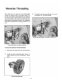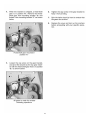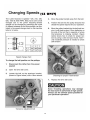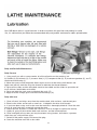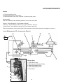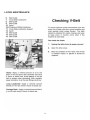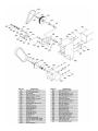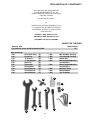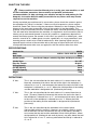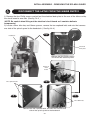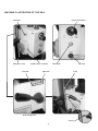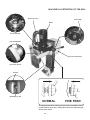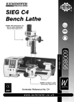
1
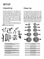
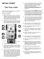
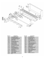
SIEG C6B Variable
Speed Lathe
600870 Mill/Drill Attachment
for the C6B Lathe.
(Manual See Pages 31-49)
200100
User Manual
200100 C6B Variable Speed Lathe.
(Manual See Pages 01-30)
W
AXMINSTER
2005
Axminster Reference No:C6B
w w w. a x m i n s t e r. c o . u k
W H I T E
1
L
K
Lathe Accessory's
B
M
G
H
A
F
D
C
N
O
P
Q
R
E
J
T
S
I
A) 1 No. Tailstock Centre
Gears
B) 1 No. Headstock Dead Centre
K) 1 No. 30 Teeth
C) 3 No. External Jaws
L) 1 No. 40 Teeth
D) 2 No. Motor Brushes
M) 2 No. 42 Teeth
E) 1 No. ‘C’ Spanner
N) 1 No. 50 Teeth
F) 1 No. Spanner for Change Wheel
O) 1 No. 52 Teeth
G) 1 No. Leadscrew Reversing Sprocket
P) 1 No. 60 Teeth
H) 1 No. Chuck Key
Q) 1 No. 66 Teeth
I) Set of Spanners 19,14,10,7mm
R) 1 No. 70 Teeth
J) Set of Allen Keys
S) 1 No. 75 Teeth
T) 1 No. 80 Teeth
2
IDENTIFICATION
15
14
7
1
8
16
20
19
22
3
2
21
4
5
13
6
23
9
12
10
18
23
11
17
1. Thread Pitch Gearing & Speed Charts
2. Lathe Forward/Reverse Switch
3. Machine ID/Safety Label
4. Emergency Stop Switch
5. Lathe Power Indicator Light
6. Selector Switch
7. Headstock Eyeshield
8. Lathe Chuck
9. Carriage Feed Handwheel
10.Cross Slide Handwheel
11.Automatic Carriage Feed Lever
12.Compound Slide
13.Tool Post
14.Tool Post Lock Handle
15.Compound Slide Handwheel
16.Tailstock Centre
17.Tailstock Clamp Bolt
18.Tailstock Axis Alignment Indicator
19.Tailstock Barrel Handwheel
20.Tailstock Centre Lock
21.Variable Speed Control Knob
22.Fault Lamp
23.Fuse Cap
24. Lathe Bed
3
6.
INITIAL START
Turn the Selector Switch (F) to 'Lathe' position.
Release the Emergency Stop Switch (A) by
turning the knob head to right, the Power
Indicator Light (B, green) lights.
Then selector the Reverse/Forward ( C) to the
left (means the spindle rotate direction is
clockwise).
Switch on the machine by GENTLY turning the
Variable Speed Control Knob (D) clockwise. A
click will be heard as the motor power is turned
on, but the spindle will not rotate until the knob
is turned clockwise a little further. Speed will
increase progressively as the knob is turned.
8.
C
If the lathe over-loads, for example, cutting too
much. A Fault Lamp (E, yellow) will light. Just
turn off the power by switching off the Variable
Speed Control Knob (D) then switch it on
again, the machine restarts.
E
D
A
then refer to step (7).
B
F
G
Lathe Symbol
Mill Symbol
4
OPERATIONS
Fault Lamp
FWD/REV Switch
Indicator
Variable Speed
Emergency Stop
Control
Button
Power Indicator
LED
Selector Switch
Fuse
5
6
6
7
8
9
10
11
12
13
(C6 ONLY)
14
Your C6B bench lathe is a precision tool. In order to maintain this precision and prolong its useful
life, it is advised that you follow the recommended daily and periodic maintenance tables printed below.
Daily and Periodic Maintenance
Daily Pre-use
1. Using an oil can with a narrow nozzle, oil all the oil points on the machine, incl.
A) Saddle (4), B) tailstock (2), C) traverse slide (1), D) compound slide (2), E) leadscrew gearbox (2), and F)
leadscrew end bearing (1).
2. Move the traverse and compound slides to give access to their drive shaft threads and
lightly coat with oil, work the oil up the threads to lubricate the thread followers.
3. Spray-oil the slides and the lathe bed, exercise the saddle and the slides to spread the oil
to all surfaces, both hidden and visible.
4. Spray up under the rack cover to lubricate the rack. (G)
5. Apply oil to the change gears and their axle mountings. (H)
Daily after-use
1. Clean all swarf and chips away from the machine bed, slide surfaces, and the tool post.
2. Exercise the slides and ensure no swarf etc., is lodged in the drive shaft tunnels.
3. If you have been using ʻsudsʼ make sure the machine is thoroughly dried off. Clear the suds
tray of all swarf and chips, especially around the drain.
4. Check the tool, ensure it is usable the next time, if not re-sharpen or replace the tool tip.
5. Lightly oil spray all the machine beds and surfaces, and the tailstock barrel.
6. Clean and lightly oil any tools you may have been using (centres, drill chucks, spanners
chuck keys etc, and put them away.
7. Switch off the power supply. Disconnect the plug.
8. Cover the machine over with a dust cloth.
15
LATHE MAINTENANCE
Weekly
a) Check the belt tension.
b) Check the tautness of the slides.
c) Check the level of the suds reservoir. (if you are using suds).
Accessories
May we recommend the following products for use with your C6B
Grease - Rocol Saphire 2 (Part number: 810129).
Lubricant - Rocol Slideway lubricant spray (Part Number: 810141).
Cutting Fluid - Rocol Multisol cutting fluid (Part Number: 810140).
There are numerous accessories listed for the machine listed in the Axminster catalogue in section 2.
LATHE MAINTENANCE (OIL LUBRICATION POINTS)
G
A
D
B
C
Oil
E
H
F
Change Gear
1
1.
2.
3.
4.
5.
2
Fixed Shaft Gear
Synchronised Counter Pulley
Upper Adjustable Shaft
Lower Adjustable Shaft
Pivot Shaft
3
4
5
16
LATHE MAINTENANCE
17
18
19
20
21
22
23
24
25
26
27
28
29
30
Mill Attachment for
the C6B Lathe
User Manual
600870
W
AXMINSTER
W H I T E
2004
DECLARATION OF CONFORMITY
The undersigned, Ole Stilling authorised
by Shanghai SIEG Machinery Co., Ltd.
No.555 Caofeng Rd., South to No. 17 Bridge of
Caoan Rd., Shanghai
declares that this product:
X2
manufactured by Shanghai SIEG Machinery Co.
is in compliance with the following standards or
standardisation documents in accordance with
Council Directives
EN55014-1:2000, EN55014-2:1997
EN61000-3-2:2000, EN61000-3-3:1995
(89/336/EEC amended by 93/68/EEC)
WHATʼS IN THE BOX
Quantity Item
1 No. Mill with Chuck and M12 Draw Bar fitted
Box containing:1 No.
1 No.
1 No.
2 No.
2 No.
1 No.
1 No.
1 No.
1 No.
1 No.
Set of Allen Keys
Chuck Key
ʻCʼ Spanner
ʻTʼ Slot Keepers
Steel Pins
Tommy Bar
Oiling Bottle
36mm Spanner
19mm Spanner
10mm Spanner
Model Number
X2
(A)
(B)
(C)
(D)
(E)
(F)
(G)
(H)
(I)
(J)
1
1
1
3
No.
No.
No.
No.
Mill Support Casting
Tilt Housing Casting
36mm Nut
M8x30 Caphead bolts
and washers
M8x35 Caphead bolts
and washers
Mill/Drill Table
M10 Drawbar
3/8" Drawbar
4 No.
1 No.
1 No.
1 No.
G
B
E
D
C
A
J
F
I
H
32
WHATʼS IN THE BOX
!
Please read the Instruction Manual prior to using your new machine; as well
as the installation procedure, there are daily and periodic maintenance
recommendations to help you keep your machine on top line and prolong its life.
Keep this Instruction Manual readily accessible for any others who may also be
required to use the machine.
Having unpacked you machine and its accessories, please check the contents against
the equipment list "Whatʼs in the box", if there are any discrepancies, please contact
Axminster Power Tool Centre using the procedures laid down in the catalogue. Please
dispose of the packaging responsibly, much of the material is bio-degradable. The
machine and its accessories will arrive coated with heavy corrosion preventative grease.
This will need to be cleaned from the machine, its components and accessories prior to
it being set up and commissioned. Use coal oil, paraffin or a proprietary degreaser to
remove the barrier grease. Be warned, it will stain if you splash it on clothing etc., wear
overalls, coverall et al., rubber gloves are also a good idea, as is eye protection if your
cleaning process tends to be a little bit enthusiastic. After cleaning, lightly coat the
exposed metal surfaces of the machine with a thin layer of light machine oil. N.B If you
used paraffin/kerosene make sure you apply this thin film sooner rather than later.
SPECIFICATIONS
Axminster No
Motor
Quill Travel
Spindle Speeds
Spindle Taper
Draw Bar Threads
Drilling Capacity
End Mill Capacity
Face Mill Capacity
Weight
600870
230V a.c. 50 Hz. 220V d.c. 350W
30mm
Low Gear 0-1100rpm (variable) High Gear 0-2500 rpm (variable)
No. 3 MT
M10,3/8"
13mm
16mm
30mm
35kg
DEFINITIONS
ʻXʼ Axis.
This is the axis described by the work table as it is moved side to side.
Normally, movement that moves the tool to the right in the workpiece is
referred to as +ve ʻXʼ, and movement that moves the tool to the left in the
workpiece is referred to as –ve ʻXʼ. Where the initial position of the tooling
and the worktable is designated 0,0. (Horizontal plane only).
ʻYʼ Axis.
This is the axis described by the work table as it is moved from front to
back. (Traverse) Normally movement that moves the tool to the front in
the workpiece is referred to as-ve ʻYʼ, and movement that moves the tool
to the rear in the workpiece is referred to as+ve ʻYʼ. Where the initial
position of the tooling and the worktable is designated 0,0.(Horizontal
plane only).
ʻZʼ Axis
This is the axis described by the worktable in the vertical plane.
(Not possible with this machine). However, to establish a point in space,
the co-ordinates can be transferred to the ʻtipʼ of the tooling, whereby, if
we assume that the tool and the worktable in their initial positions, where
designated 0,0,0, (Horizontal and vertical planes) any point above the tool
tip is referred to as +ve ʻZʼ, and any point below the tool tip is referred to
as -ve ʻZʼ
33
INITIAL ASSEMBLY - REMOVING THE SPLASH GUARD
!
DISCONNECT THE LATHE FROM THE MAINS SUPPLY
1) Remove the four Phillip screws and pull out the electrical back plate to the rear of the lathe and lay
the circuit board to one side. (See fig 1 & 2 )
(NOTE. Be careful when lifting out the electrical circuit board as it contains delicate
components)
2) Locate a 5mm allen key and 10mm spanner, remove the two caphead bolts and nuts that secures
one side of the splash guard to the headstock. ( See fig 3 & 4)
Fig 1
Headstock
Electrical
back plate
Remove the four Phillip screws
and lift out the electrical panel
Electrical
circuit
board
Two caphead bolts
Fig 2
Fig 4
Fig 3
Two 10mm nuts
Remove the two caphead bolts and nuts that secures one
side of the splash guard to the headstock
34
INITIAL ASSEMBLY - REMOVING THE SPLASH GUARD
3) Loosen the two bolts and washers which clamps the opposite
end of the splash guard to the side of the lathe bed, below the tailstock.
(See fig 5)
4) Remove the splash guard and place safely aside.
Fig 5
INITIAL ASSEMBLY - MOUNTING THE MILL
!
WARNING
When mounting the Mill to the Lathe, we strongly advise you get
the assistance of another person because of the weight of the
machine.
A
Step 1
Grub screws
Remove the four grub screws to
the side of the lathe bed and
place safely aside.
D
C
B
Step 2
B
A
35
Locate the angle support casting and
four M8x35 caphead bolts and washers.
Secure the angle support to the side of
the lathe bed. DO NOT OVERTIGHTEN
INITIAL ASSEMBLY - FITTING THE MILL
Step 3
TWO MAN
ASSEMBLY
B
Leg lock nut
!
WARNING
HEAVY
Tip the lathe forward and have your assistant
thread the support leg up into the angle support
casting. Adjust the support leg until it makes
contact with the surface of your bench or stand,
tighten the lock nut to lock the leg in position.
D
C
Step 4
C
B
Locate the tilt housing casting and three M8x30
caphead bolts and washers. Offer up the
pre-drilled holes with the holes in the support
casting and secure in place using the
M8 bolts and washers.
A
Lathe socket
Mill power plug
Step 5
Step 6
D
Insert the Millʼs power plug into the socket
in the rear of the lathe as shown.
Lift the mill assembly and slide it over the tilt
housing shaft until it is flush against the tilt
housing. Locate the 36mm nut and spanner and
lock the mill assembly in position.
DO NOT OVER TIGHTEN
Make sure that everything is secure then replace the splash guard as described on pages 34-35.
36
INITIAL TESTING
!
Please read the section entitled Identification and Parts description so that you may
more easily identify the parts to which reference is made in the text.
Testing
When the Mill is mounted to your satisfaction, proceed as follows:a) Close the chuck jaws
b) Check the millhead is ʻlockedʼ in position on the column.
c) Check that all loose items are removed from the worktable.
d) Set the worktable approximately mid-positioned under the chuck jaws.
e) Check the speed control is switched OFF (fully anti-clockwise).
f) Rotate the Lathe/Mill selector switch on the latheʼs control panel to the milling position.
g) Select L (Low) on the gear box.
h) Connect the machine to the mains supply, open the switch shroud and press the on button (Green),
check the green power light comes on, lower the lid of the switch shroud (Do Not Close).
i) Turn the Speed Control Switch On (Clicks On).
j) Check the Amber LED (Fault Light) is illuminated and the green light is illuminated.
k) Turn the Speed Control to Off (Clicks Off), the Amber LED is now Off and the Green light stays on.
l) Turn the Speed Control Switch On and advance until the Chuck starts to rotate.
m) While itʼs running press the Emergency Stop button, check the machine stops, check that the
green light and the Amber LED is on. Disengage the Emergency Stop button by opening the switch
shroud, turn the Speed Control Switch to Off ( All lights are off).
n) Press the on button, turn the Speed Control On and advance until the chuck starts to rotate.
o) Over a period of approximately 5 minutes advance the speed in stages to maximum, run at
maximum for at least 2 minutes, check that there is nothing untoward, (no excessive vibration, speed
progression is smooth etc.). Stop the spindle and change the gear selector to H (High), carry out the
previous check.
p) If all the above checks are correct, stop the spindle, (turn the speed control to zero and press the
Off button (Red). Push the Tri-lever feed handle in (if necessary ʻjoggleʼ the feed to enable the gears to
mesh), exercise the quill up and down, check the movement is smooth and precise.
q) With the Tri-lever engaged, raise and lower the quill using the fine feed control. Check the
movement is smooth and precise, there are no hard spots and the feed doesnʼt bind up. Disengage
the tri-lever by pulling the assembly back.
r) Ensure the head lock clamp is loosened and exercise the rise and fall, driving the head up and down
the tool post. Check the movement is smooth and tight. Leave the head fairly well down the tool post
for the next check.
s) Loosen the 36mm tilt clamp bolt, to the rear of the tool post and tilt the tool post to the left or right,
clamp the tool post in an arbitrary position and tighten the bolt. Check that the tool post remains locked
in place.
t) If all the above checks are correct, your mill is now ready for use.
37
PARTS IDENTIFICATION AND DESCRIPTION
Please take some time to identify the various parts of your machine so that you are
familiar with the terminology we will use to enable you to set up and operate your Mill
safely and correctly.
Main tool post
This is the column of the mill, it is an 65 x 50 bar with a dovetail
slide machined on the front onto which the milling head is
mounted, the lower part there is pre-drilled hole which sides over the
tilt housing shaft and secured in place by a 36mm nut. On the left
side of the post a scale, graduated in mmʼs, is mounted to read against
a pointer mounted on the head casting.
Rise and fall
mechanism
Rise and fall, there is a dovetail slide machined on each side of the the
headbox support column which mounts a through shaft. A pinion gear is
mounted on the shaft inside the headbox that meshes with a rack on
the support column driving the pinion shaft will cause the headbox to
rise and fall up and down the headbox support column. The part of the
shaft protruding from the headbox has a hole through it to mount the
tri-lever feed assembly.
Tilt housing
The tilt housing is mounted to the base casting using 3 M8x30 caphead
bolts and washers. The tool post is mated to the housing and clamped
by a 36mm nut. The main tool post can tilt 45 (degrees) from the
vertical either left or right. There is a pointer and a scale mounted on
the housing to give an indication of the amount of tilt that has been
applied.
Milling head
This is the ʻmilling machineʼ and the descriptions of its
various parts and components are detailed as follows:-
Milling head
casting
The main casting to which all the components are attached. The
head has a dovetail housing machined at the rear, which allows
the casting to be fitted to the Main Tool Post. The left side of the
dovetail slide is fitted with a gybe strip to maintain the fit.
Head clamp
Located to the right side of the main tool post above the gybe strip
adjusters and locknuts is an handled bolt that clamps the gybe strip
against the slide to effect a locking action for the rise and fall of the
head. (See page 42)
Motor and
gearbox
The motor and gearbox assembly are mounted above the main
head casting at the top of the arbor sleeve. The motor drive is
geared through to the spindle with an intermediate 2:1 gearbox.
Gear change
lever
The gear change lever allows the selection of the high or low ratio
of the gear train. The speed of the spindle is then governed by the
speed control on the motor panel. (You may have to ʻjoggleʼ the
chuck/tool to aid the meshing action).
Motor
A 220V d.c. motor rated at 350W.
38
MACHINE ILLUSTRATION OF THE MILL
Motor
Feed handle
Control unit
Rise and fall Tri-lever feed
Rack
Main tool post
Angle support casting
Guard
Depth stop
Chuck
Scale
Pointer
0-45˚tilt either
direction
Tilt housing assembly
39
PARTS IDENTIFICATION AND DESCRIPTION
Tri-Lever feed
Three levered handle that is used to drive the quill (and hence the
chuck or the tool) up and down. The boss of the handle is fitted to the
end of a ʻsplinedʼ gear shaft. This ʻsplinedʼ gear is, in turn, engaged in
the rack cut into the quill body. The other end of the ʻsplinedʼ shaft is
engaged in a contra-wound spring, this provides counter balance to the
weight of the quill, arbor, chuck and drill, giving a more controlled ʻfeelʼ
during drilling operations. It also retracts the quill when drilling is
completed.
Fine feed
assembly
The fine feed assembly floats around the splined gear shaft that
drives the quill up and down. When the action of the fine feed
mechanism is required; pushing the tri-lever feed handle in ʻengagesʼ
the knob of the fine feed control meshes the gearing (you may have to
ʻjoggleʼ the feed handle to aid the meshing action) between the splined
shaft and the fine feed control shaft; this enables the spindle to be
driven by the fine feed control wheel with greater precision. Behind the
boss of the fine feed control wheel handle is a graduated ring (thimble)
so that the movement of the quill can be measured. The thimble is
held to the drive shaft by friction, and can be pre-positioned to
establish a predetermined start or stop dimension.
Quill hold pocket
The size of the machine precludes any ʻfancyʼ locking mechanism for
the quill. There is a blind pocket on the spindle that accepts the tommy
bar supplied in the tool kit, to enable the spindle to be held in position
whilst the draw bar is loosened.
Draw bar cover
A moulded plastic cover that clips into the top of the Motor Gearbox
assembly, to afford protection from the rotating top of the draw bar,
when the quill is at the top of its travel.
Draw bar
(unseen)
This is a metal rod, threaded at one end and with an 19mm
squared shank and flange machined on the other. It is fitted through
the spindle mandrel to hold the fitted tool/tooling hard into the No. 3 MT
taper of the spindle shaft.
Motor control
panel
Power On LED
Green LED that indicates that power is available to the motor. i.e.
mains is applied, fuse is intact and the Emergency stop switch is
not activated.
Fault LED (marked UNNORMAL)
Amber LED that indicates that there is a fault or an incorrect
control sequence. i.e. the chuck guard interlock has been activated
or the speed control is activated. The Motor will not run if the fault LED
is illuminated. If the safety interlock is activated, the safety interlock will
remain in force until the interlock is reset and the start sequence
re-initiated.
Fuse Cap
Access cap for the 20mm fuse cartridge (1 Amp 250V) Speed Control
Knob Round raised ridge knob connected to the circuit that controls the
spindle speed (0-1100 rpm or 0-2500 depending upon the gearbox
selection).
40
MACHINE ILLUSTRATION OF THE MILL
Fault LED
Speed control knob
Emergency stop
ON/Off switch & shroud
Low ratio
High ratio
Power LED
Fuse cap
Scale
Gear change lever
Pointer
41
MACHINE ILLUSTRATION OF THE MILL
Draw bar cover
Head clamp
Motor
Top of draw bar
Fine feed thimble
Circuit control box
Fine feed control
Spindle
Quill hold pocket
NORMAL
FINE FEED
To engage the fine feed control push the tri-lever assembly in until it
meshes with the bevel gear. Pulling the tri-lever back will disengage
the fine feed control.
42
GENERAL OPERATING INSTRUCTIONS
!
Warning Do not operate the mill in any function unless the head clamping lever is
tightened.
TOOL CHANGING
Note. The taper socket in the spindle mandrel does not have a ʻdrive flatʼ and all
tooling, including the drill chuck is secured and driven by the taper lock and the draw
bar.
Make sure the power is switched off or better still remove the power from the machine.
Locate and put to hand the 19mm A/F spanner and the tommy bar. Remove the Draw Bar
Cover. Hold the quill immovable by inserting the tommy bar into the quill hold pocket and
loosen the draw bar. Unscrew two or three turns and then strike sharply with a hammer
(preferably a copper face, to prevent the head of the draw bar peining over) this will break
the lock between the tool and the spindle tapers .
Unscrew the draw bar from the tool. Ensure the tool is supported, i.e. will not fall onto the
workpiece/table et al. When it is free put the tool carefully aside, remove the draw bar, check
the thread, check the taper and the thread of the new tool are clean and undamaged,
introduce the new tool into the taper, re-insert the draw bar and screw into the top of the tool.
Screw in the draw bar finger tight. Hold the quill immovable and tighten with the spanner. DO
NOT OVERTIGHTEN. Replace the draw bar cover.
Remove all tooling and reconnect the machine. Ensure the tool path is clear, switch on, and
check that the tool is correctly seated, is running true etc. If all is O.K, proceed.
GERERAL SAFETY POINTS
Milling (all cases)
Ensure the workpiece is securely clamped to the table.
Along the longitudinal
Axis (X)
Ensure that the quill is locked in position before
milling is commenced. Ensure the traverse slide lock
is tightened.
Along the Traverse Axis (Y) Ensure that the quill is locked in position before milling is
commenced. Ensure the worktable lock is tightened.
Milling or Drilling Vertically
(Z)
Ensure the traverse slide and the worktable locks are
tightened.
SETTING AND ADJUSTMENTS
Milling head adjustment
The Milling Head is mounted over a dovetail section. In order to maintain the ʻtightnessʼ of the
fit; between the sloping surface of the component and its mating surface, on the right hand
side, a gybe strip has been inserted. To adjust the gybe strip, use the supplied allen key and
spanner, release the lock nuts and screw the gybe strip grubscrews clockwise to compensate
for any slackness or anti-clockwise to loosen the movement. Check, using the rise and fall
drive feed handles, that the head moves smoothly, If not, repeat the adjustments until the
movement is smooth and tight over the whole of the travel.
43
MILL TABLE ASSEMBLY
The Mill/Drill includes a milling table as an accessory. To install the milling table the
compound slid must be removed from the cross slide from the lathe bed. Once installed, the
milling table can move back and forth with the cross slide. Follow the instruction below to
install table.
Fig A
1) Using a 12mm spanner remove the
two bolts that secures the compound
slide to the cross slide, remove the
compound slide and place safely aside.
(See fig A)
Fig B
Remove the two bolts using a 12mm spanner,
remove the compound slide from the cross slide.
Phillips screwdriver
2) Using a Phillips screwdriver remove the four grub
screws from the cross slide and place safely aside.
(See fig B)
Caphead bolt
Fig C
3) Locate the milling table and the
supplied caphead bolts. Lower the
table onto the cross slide, line up the
holes and insert and secure the table
using a 6mm allen key. (See fig C)
44
Milling table
MAINTENANCE
Your Mill is a precision tool. In order to maintain this precision and prolong its useful
life, it is advised that you follow the recommended daily and periodic maintenance
tables printed below.
Daily and Periodic Maintenance
Daily
1. Carry out a visual inspection. Repair any damage immediately. Minor damage to the beds
should be taken out with an oilstone.
2. Move the worktable and the traverse feed back and forth by hand, check that the movement
is smooth.
3. Spread a light film of oil over the worktable and the traverse slide bed.
4. Oil the end bearings of the drive shafts. Squirt oil onto the slide faces of mating components.
5. Exercise the components to ensure the oil is spread over both visible and obscure surfaces.
Daily after-use
1. Clean all swarf and chips away from the machine bed, slide surfaces, and the tool post.
2. Exercise the slides and ensure no swarf etc., is lodged in the drive shaft tunnels.
If you have been using a coolant make sure the machine is thoroughly dried off.
3. Check the tool, ensure it is usable the next time, if not re-sharpen or replace the tool tip.
4. Lightly oil spray all the machine beds and surfaces.
5. Clean and lightly oil any tools you may have been using (drill chucks, spanners, chuck keys
etc), and put them away.
6. Switch off the power supply. Disconnect the plug.
7. Cover the machine over with a dust cloth.
Weekly
1. Move the traverse slide fully back to give access to the tunnel, blow out to make sure all
swarf is cleared away and heavily spray oil the tunnel, exercise the slide to work the oil into
the drive thread and to lubricate the dog.
2. Spray oil the slide and the worktable bed, exercise the worktable to spread the oil to all
surfaces, both hidden and visible.
3. Spray oil the underside of the machine onto the drive screws, exercise to ensure the
oil is coating all components.
4. Clean and spray oil the rise and fall drive screw, exercise to ensure all parts are coated.
5. Check the movement of the worktable, the traverse slide and the head, check they are
smooth and ʻtightʼ, if necessary reset the gybe strips until the movements are smooth and
tight.
6. Wipe the quill outer sleeve clean and lightly oil, exercise the quill to spread the oil in
the sleeve bushes.
Monthly
a) Give the motor a good ʻblow throughʼ to remove any dust, dirt etc,
b) Check all the interlocks function correctly.
Accessories
There are numerous accessories for the machine listed in the Axminster catalogue.
Some are illustrated at the rear of this manual. (See page 47)
45
MAINTENANCE OILING POINTS
OIL
Oil
46
MILL ACCESSORIES
Rotary Milling Vice
for Micro Mill 55mm
Part No: (100034)
50mm Release Vise
Axminster Micro
Mill Collets
#2MT 6mm collet
Part No: (100023)
Quick vice 50mm
Part No: (100022)
#2MT 10mm collet
Part No: (100024)
Axminster Power Tools
Catalogue
Micro Mill Clamping Kit
Clamping kit
Part No: (100033)
Axminster Bull Nose Slot Drills
Axminster HSS End Mills
Axminster HSS
Slot Drills
Metric Screwed Shank Two Flute Bull Nose Slot Drills
Order No
Description
610170-14
610171-14
610172-14
610173-14
610168-14
Bull Nose Slot Drill 3mm
Bull Nose Slot Drill 4mm
Bull Nose Slot Drill 6mm
Bull Nose Slot Drill 8mm
Bull Nose Slot Drill 10mm
Metric Screwed Shank Three Flute End Mills.
Metric Screwed Shank Two Flute Slot Drills.
Order No
Description
Order No
Description
610177-14
610178-14
610179-14
610180-14
610174-14
3mm End Mill
4mm End Mill
6mm End Mill
8mm End Mill
10mm End Mill
610184-14
610185-14
610186-14
610187-14
610181-14
Slot Drill 3mm
Slot Drill 4mm
Slot Drill 6mm
Slot Drill 8mm
Slot Drill 10mm
47
PARTS BREAKDOWN FOR THE MILL
48
PARTS BREAKDOWN FOR THE MILL
49
SIEG C6B Variable Speed Lathe
200100
Axminster Reference No: C6B
W
AXMINSTER
W H I T E
Axminster Devon EX13 5PH UK
FREEPHONE 0800 371822
2005
www.axminster.co.uk