1
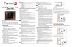
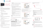
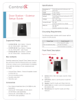
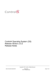
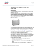
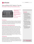
™
NOTE: Video Intercom using 802.11b is not
recommended or supported for Video
Intercom. Control4 recommends Wireless-N
for Video Intercom. See “Wireless Network
Limitations” and “Power and Network
7” In-Wall Touch Screen
with Camera
Installation Guide
Installation Options.”
• Option 1: Ethernet with PoE. The Ethernet
network connection is provided through the PoE
Injector. No additional wiring is needed.
• Option 2: Ethernet with AC. Connect the Touch
Screen to one of the RJ-45 LAN ports on the
gateway/router using the RJ-45 Ethernet cable.
• Option 3: WiFi with AC. The internal WiFi will
communicate with the LAN’s WAP. If the LAN has
a WAP set up, no additional wiring is needed.
Supported Models
Introduction
The Control4® 7” In-Wall Touch Screen with Camera
offers complete system control in an elegant and
compact design. This Touch Screen is equipped
with a capacitive Touch Screen and four (4)
programmable shortcut buttons plus Audio and
Video Intercom (with a built-in camera) using SIP.
The available power options are AC power or Powerover-Ethernet (PoE); the network options are WiFi
or Ethernet connections. This Touch Screen supports
new construction or retrofit installations.
• AC. AC power is used to power the Touch
Screen when using an Ethernet or WiFi network
connection.
• PoE. PoE is used to power the Touch Screen
• C4-TW7C0- BL - 7 Inch Wall Mount Capacitive
Touch Screen with Camera, Ethernet/WiFi, PoE/
Universal Voltage, Black
• C4-TW7C0- WH - 7 Inch Wall Mount Capacitive
Touch Screen with Camera, Ethernet/WiFi, PoE/
Universal Voltage, White
Associated SKUs:
• C4-TSWMC5-EG-WH – 5” In-Wall Touch Screen,
White (no camera)
• C4-TSWMC7-EG-WH – 7” In-Wall Touch Screen,
White (no camera)
• C4-TSWMC5-EG-BL – 5” In-Wall Touch Screen,
Black (no camera)
• C4-TSWMC7-EG-BL – 7” In-Wall Touch Screen,
Black (no camera)
Box Contents
when using an Ethernet or WiFi network
connection.
Carefully unpack the contents of the box, and make
sure the following items are included. If any item is
The following table shows the available network
missing or damaged, please contact your Control4
options with power.
Reseller.
• Ethernet with PoE
• 7” In-Wall Touch Screen with Camera
• Ethernet with AC
• Power box (used to power the Touch Screen)
• WiFi with AC
• Two (2) screws to attach the power box
• Warranty card
1
™
Dimensions
(H x W x D)
4.88” x 7.2” x .60” (124 mm x 183 mm x
15.24 mm)
Weight
1.15 lbs. (.52 kg)
Shipping Weight
1.8 lbs. (.81 kg)
Network
WiFi (802.11 b/g/n) wireless access
point (WAP) already configured
to communicate with a Control4
Controller (e.g., HC-800). Wireless-N is
recommended for Video Intercom.
7” In-Wall Touch Screen
with Camera
Installation Guide
Notes: (1) Intercom usage. 802.11b is not
recommended or supported for Video
Intercom. (2) Wireless-N is recommended
for Video Intercom. Even with Wireless-N,
broadcasting to several devices will
degrade Video Intercom response time and
images. Broadcasting to additional devices
will further degrade performance. See
“Wireless Network Limitations.”
Accessories
•
PoE. Control4 Power over Ethernet Injector, sold
separately (AC-POE1-B).
• Back Box Options. There are four (4) back
box options available for this Touch Screen’s
installation. Metal and plastic back boxes
are available for new construction or retrofit
Requirements
To install the 7” In-Wall Touch Screen with Camera,
Control4 requires the following:
installations.
•
5” and 7” In-Wall Touch Screen Back Box Kits New Construction
with a Control4® system.
•
Control4 7” Touch Screen custom back box
installed (OS 2.2.1 or later). See “Accessories.”
- 5” and 7” In-Wall Touch Screens Wall Box,
New Construction, Plastic (C4-NWB57C-P)
A Home Controller fully installed and configured
•
If using Ethernet with PoE power:
- Ethernet network installed and available that
- 5” and 7” In-Wall Touch Screens Wall Box,
includes a gateway/router/switch
New Construction, Metal (C4-NWB57C-M)
- Control4 PoE Injector (model #AC-POE1-B)
5” and 7” In-Wall Touch Screen Back Box Kit -
or another third-party PoE Injector or switch
Retrofit
(certified to UL/ANSI standards).
- 5” and 7” In-Wall Touch Screens Wall Box,
- Two (2) Ethernet CAT5 cables: (1) one that
runs from the Ethernet gateway/router/switch
Retrofit, Plastic (C4-RWB57C-P)
to the PoE Injector/switch and (2) one that runs
- 5” and 7” In-Wall Touch Screens Wall Box,
from the PoE Injector/switch to the Ethernet
Retrofit, Metal (C4-RWB57C-M)
See the Control4 5” or 7” In-Wall Touch Screen
Wall Box Installation Guide - New Construction or
connection in the Touch Screen’s back box.
•
If using Ethernet with AC power:
- Ethernet network installed and available that
5” or 7” In-Wall Touch Screen Wall Box Installation
includes a gateway/router/switch
Guide - Retrofit for back box installation details.
- Access to in-wall AC power (a neutral
connection is required)
Specifications
- One (1) Ethernet CAT5 cable that runs from
the Ethernet gateway/router/switch to the Touch
Screen
Wireless
7” 16:9 wide VGA Color LCD Module
Resolution: 800 x 480
Camera: 640 x 480 VGA
Brightness: 350 nits
Built In IEEE802.11 b/g/n Wireless LAN
Integral Antenna (b/g/n supported)
Authentication: WEP, WPA, WPA2
Screen
- A 14-gauge electrical wire long enough to pull
between the Touch Screen and the power source
•
If using wireless with AC power:
- Wireless network (WiFi 802.11 b/g/n) installed
and available with a wireless access point (WAP)
- Access to in-wall AC power (a neutral
2
connection is required)
Back View
- A 14-gauge electrical wire long enough to pull
between the Touch Screen and the power source
Figure 2. Back View - 7” In-Wall Touch Screen with
Camera and Power Box
Front and Rear Panel Descriptions
2
Front View
Figure 1. Front View - 7” In-Wall Touch Screen
3
4
1
1
1
Wire Connection. Hot (H) uses Black wire; Return
(R) uses White wire.
2
2
RJ-45 port for Ethernet Connection. Ethernet
port available for either a standard Ethernet
source that provides network communication
only OR a PoE source that provides power to the
device and network communication.
1
Display. 7” viewing area, Touch Screen with 800 x
Touch Screen Placement
480 resolution.
2
Shortcut buttons (4). For custom programming;
Place the Touch Screen in a convenient location at
to initiate an action or sequence of actions. Use
eye level, typically near the entrance of the room,
Composer Pro or Composer HE to configure
approximately 57 to 61 inches (145 cm to 155 cm)
these buttons.
from the floor (see Figure 3).
3
Green LED. Lets you know the camera is on.
4
Camera. For Video Intercom calls.
NOTE: Consider the camera on the panel and
the height of the people in the home who will
Dimensions
use the camera for Video Intercom.
- Front dimensions. 7” Touch Screen (H x W x D):
4.88” x 7.2” x .60” (124 mm x 183 mm x
Figure 3. Touch Screen Placement
15.24 mm)
- Back box dimensions. 7” Touch Screen
(H x W x D): 2.7” x 4.1” x 2.4” (68 mm x 104 mm
x 61 mm)
New Device
- Power box dimensions. 7” Touch Screen (H x W
x D): 2.8” x 4.5” x 1.8” (71 mm x 114 mm x 46 mm)
AC Power
(unless using PoE)
Touch Screen Removal
Use the small hole located under the Touch Screen to
remove the Touch Screen from the wall (for details,
see Figure 10 in “Troubleshooting”).
LED Indicator
The LED on the Touch Screen indicates the camera
status of the camera and booting information as
described in the next table.
3
Camera LED Color/
CAUTION! Do not attempt to use PoE and
Touch Screen Status
AC power at the same time. Choose only one
State
Off
- Camera is off
power option.
Green
- Camera is on
ATTENTION! Ne pas tenter d’utiliser PoE et
Green (blinks slowly)
- Booting up
AC en même temps. Choisir une seule option
Green (blinks
rapidly)
- Restoring (during a factory
restore)
Installation
WARNING! Before installing the Touch Screen,
switch off the circuit breaker or remove the
fuse from the fuse box.
AVERTISSEMENT! Pour l’endroit où vous
installez l’écran tactile, coupez le disjoncteur
ou enlevez le fusible de la boîte de fusible.
IMPORTANT! Before you can complete the
instructions below, you must have a 7” Touch
Screen back box installed according to the
documentation provided in the back box kit.
d’alimentation.
Option 1: Ethernet Connection with a PoE Injector or
a Third-Party Injector or Switch
PoE supplies DC power on the Ethernet cable using
a PoE Injector (model #AC-POE1-B) or a third-party
PoE solution to provide the Touch Screen with power
and a network connection. The Touch Screen works
with the Control4 PoE Injector or a third-party PoE
Injector.
To set up your PoE and Ethernet connection with a
PoE Injector, see Figure 4.
1
instructions in your PoE’s installation guide if
See “Accessories” for details.
provided. Control4 PoE Injector instructions are
IMPORTANT! En coupant l’ouverture pour la
boîte de mur, ne coupez pas l’ouverture trop
grande. Soyez conservateur et agrandissezavec précaution la comme nécessaire. Voyez
que <<Accessories>>.
IMPORTANT! When cutting the opening for
Attach the PoE Injector according to the
provided later in this document.
2
Pull the Ethernet cable from that location to
where you want to install the Touch Screen.
Figure 4. Ethernet with PoE - Requires Ethernet
Connection to PoE Injector
the back box, DO NOT cut the opening too
large. Be conservative and cautiously enlarge it
as needed.
IMPORTANT! En coupant l’ouverture pour la
boîte de mur, ne coupez pas l’ouverture trop
grande. Soyez conservateur et agrandissezavec précaution la comme nécessaire.
Power and Network Installation Options
This device uses an Ethernet or WiFi network
connection, and can be powered using PoE or AC
power.
Option 2: Ethernet Connection with AC
Choose one of the following options to install the
The Ethernet is connected directly to the switch
power and network communication.
4
(see Figure 5). This power connection requires both
neutral and hot connections.
Figure 5. Ethernet - Requires a Connection to
Figure 6. WiFi - Requires AC Power and WAP
Ethernet and AC Power
Option 3: WiFi Connection with AC
Power Installation
Prepare the plastic power box for installation into the
Place the Touch Screen above a power source, for
back box by inserting either the Ethernet cable or the
example, an outlet. Ensure that you have WiFi in the
AC power cable into the power box (see Figures 7
home (see Figure 6).
and 8), and then follow the instructions next.
NOTES: (1) Video Intercom. Although this
device supports b/g/n, 802.11 b is not
supported for Video Intercom use. (2)
AC Power Connection
The steps below represent a typical U.S. installation.
Wireless-N is recommended for Video
Intercom. See the Composer Pro User Guide
for details about the 7” In-Wall Touch Screen
1
the Touch Screen according to the national and
with Camera properties.
Wireless Network Limitations
Many WiFi Access Points handle Multicasts
local electrical codes. Installation may require
alternative wires and the use of a terminal block.
2
with Camera broadcasts video to all stations)
Thread the power cable through the bottom back
hole of the back box to the terminal block (see
(WiFi simultaneously sent to multiple devices,
for example, when the 7” In-Wall Touch Screen
Connect the wires to the AC power source for
Figure 7).
3
Strip the black and white power wire ends to 1/4”
as necessary. Using a flathead screwdriver, loosen
by slowing down transmission speed to the
the screws on the power box’s terminal block and
1 Mb basic rate. This can cause overall WiFi
connect the power wires to each terminal (see
congestion in the WiFi network during the
Figure 7).
broadcast. Video Intercom response times and
images may degrade at each device.
4
Cap the ground wire from the wall if you are
using a plastic back box. Attach the ground wire
to the back box if using a metal back box.
If a home requires a large number of WiFi
Video Intercom devices, ensure that you have
a robust WiFi network (possibly consisting of
Figure 7. AC Power Connection
multiple access points).
Power Box
Back Box
Terminal
Block
Power Cable
Connect
Wires
to Terminal
Block
5
5
Align and bend the wires carefully to fit them
Figure 8. Ethernet Connection
inside the back box.
6
Align and carefully slide the power box into the
back box.
7
Secure the power box into the back box using
Ethernet
Connection
Back Box
the screws provided.
Power Box
NOTE: Overtightening the power box screws
could result in a poor connection between the
Touch Screen and the power box and could
6
the screws provided.
also cause the Touch Screen to warp.
8
NOTE: Overtightening the power box screws
Align and slide the back of the Touch Screen into
could result in a poor connection between the
the power box. The Touch Screen is magnetic
Touch Screen and the power box and could
and should snap into place easily.
9
also cause the Touch Screen to warp.
(Optional) To secure the Touch Screen inside the
power box, remove the tape covering the bottom
security pin (see Figure 10) before attaching the
7
and should snap into place easily.
8
security pin (see Figure 10) before attaching the
Touch Screen to the power box.
and then connect it to the power box.
PoE Injector.
1
Connect the Control4 PoE Injector to an AC
outlet using the power cord.
2
Connect one of the RJ-45 LAN ports on the
gateway/router/switch to the PoE Injector’s LAN
port using the RJ-45 Ethernet cable.
3
Connect the PoE Injector’s PWR LAN-OUT
port to the RJ-45 Ethernet cable that will be
(Optional) To secure the Touch Screen inside the
power box, remove the tape covering the bottom
Connect the PoE Injector to power and the network,
The steps below describe how to install a Control4
Align and slide the back of the Touch Screen into
the power box. The Touch Screen is magnetic
Touch Screen to the power box.
Power Over Ethernet (PoE) Connection
Secure the power box into the back box using
Configuration
Configure for Wireless
(WiFi only) Connect to a WAP on the Touch Screen
(see Figure 9):
Figure 9. Wireless Configuration
connected to the Touch Screen.
4
Pull the Ethernet cable through the top back hole
of the back box to the Ethernet connector on the
top back of the power box, and then connect it
(see Figure 8).
5
Align and carefully slide the power box into the
back box until the Touch Screen is attached to
the power box.
1
After initialization, press and hold the large White
4 in the center of the Touch Screen to enter the
configuration screen.
2
6
Press the Network button on the Touch Screen’s
configuration page. The network configuration
screen displays.
3
Under Wireless, select Enable. If you don’t see
the network you want, select Other.
4
At Network Name, select to add the SSID or
wireless network when the keyboard appears.
Select Done.
5
Restore to Factory Default
If the camera’s LED blinks on and off for more than
30 seconds, the device will need to be restored.
To access the Factory Restore switch, you’ll first need
to remove the Touch Screen.
At Security, select None, WEP 64, WEP 128,
NOTE: If there’s tape on the bottom of the
WPA, or WPA2.
6
power box, simply lift the Touch Screen off
At Password, type the password on the keyboard
(see Steps 3 through 6). Remove the tape to
that appears. Press Done.
7
lock the Touch Screen in place. If there’s no
Select Connect. Notice that the IP settings
tape, the Touch Screen is locked into place. In
change. The IP address is set to DHCP by default.
8
this case, follow the instructions below.
(Optional) If you need to set a static IP address
instead, complete the following steps:
a
On the Network page, press Static.
b
Select each box one at a time and type the
1
Locate the small hole underneath the Touch
Screen’s faceplate (see Figures 10 - 13).
address: IP Address, Subnet Mask, Default
Gateway, Preferred DNS, and Alternate DNS.
c
Figure 10. Touch Screen Underside - Pin and Pinhole
When the keyboard appears, type the
Security pin
address, and then press Done.
9
Press OK to return to the Network page. You can
now connect to a Control4 Director running on a
Control4 device on the network.
Speaker
10 Press OK.
Configure in Composer Pro
2
Insert paper clip here to
remove Touch Screen
Using a small unbent paper clip, insert the paper
clip straight up and into the small hole (about
1/4”) or as far as you can. There’s another small
When the Touch Screen is physically installed and
hole inside the Touch Screen which the paper clip
appears on the home network, you can add and
needs to insert into also (see Figures 11 through
configure it for the Control4 System using Composer
13). You may need to wiggle the paper clip a bit
Pro. Choose the In-Wall 7” Touch Screen V2 driver in
to get it into the second small hole.
Composer and add it to your project.
See the Composer Pro User Guide for information
about how to add and identify the Touch Screen to
Figure 11. Locate Touch Screen Hole
Insert Paper Clip Here
Bottom of Touch Screen
the Control4 System.
Troubleshooting
Boot Up
Insert Paper Clip
Through this Hole
Too
When the device is booting up, it may take 30
seconds or longer before the Green LED turns on.
When it turns on, it blinks slowly for a time and then
turns off. After that, you will see an image on the
Touch Screen.
7
Figure 12. Insert Paper Clip Through Small Hole
change on the next power up, and will initiate the
restore process.
6
When you are finished with the restore, reattach
the Touch Screen into the power box in the wall—
top first—and then snap the bottom of the Touch
Screen back into place.
7
The Touch Screen will reboot and the factory
default firmware image will be installed. All
settings will reset to the factory default settings.
See “LED Indicator” for information about how
the LED behaves during a factory restore.
8
After a restore, the Touch Screen will need to be
updated to the same image version of the project
(e.g., OS 2.2.2 or later).
Figure 13. Paper Clip Needs to Engage Release Plate
Security plate
Warnings/Considerations
WARNING! The Touch Screen must be
protected by an external circuit breaker or
a fuse rated at 6A maximum when used in
Europe.
AVERTISSEMENT! Pour réduire le risque du
Pinhole
feu ou de choc électrique, n’exposez pas cet
appareil à la pluie ou à l’humidité.
WARNING! Do not place the Touch Screen
near sources of heat or expose to direct
sunlight for an extended period of time.
AVERTISSEMENT! Ne placez pas l’unité
près des sources de chaleur ou exposition
3
With both hands, tilt the bottom of the Touch
1:1 SCALE
C4-7” TOUCH SCREEN IN WALL-V2
Screen
out and gently remove the Touch
Screen.
4
On the back of the Touch Screen locate the small
switch (see Figure 14).
pour diriger la lumière du soleil pendant une
période prolongée.
IMPORTANT! Do not use pens or sharp
objects to navigate or make selections on
the Touch Screen. To select an item or scroll
Figure 14. Factory Restore Switch
Factory Restore
Switch
through a list, use your fingertip.
IMPORTANT! N’employez pas les stylos ou les
objets pointus pour diriger ou pour faire des
choix sur l’écran. Pour choisir un article ou un
rouleau par une liste, employez votre bout du
doigt.
IMPORTANT! Improper use or installation can
cause DAMAGE OF PROPERTY.
5
Using the tip of a straight pin or paper clip,
change the position of the switch, for example, if
the switch is in the down position, push it to the
up position. The Touch Screen will then sense the
8
IMPORTANT! L’utilisation ou l’installation
inexacte peut causer DAMAGE DE
PROPRIÉTÉ.
IMPORTANT! Using this product in a manner
product until you consult your physician.
other than outlined in this document voids
Magnetic fields can cause damage to
your warranty. Further, Control4 is NOT liable
magnetic storage media (for example, credit
for any damage incurred with the misuse of
cards, video tapes, computer hard drives, etc).
this product. See “Warranty.”
Keep all magnets at least 20 inches away from
IMPORTANT! Utilisant ce produit en quelque
all types of magnetic media. Certain electronic
sorte autre que décrit dans ce document vide
devices are sensitive to magnetic
votre garantie. De plus, Control4 n’est pas
FIELDS and may be damaged permanently or
responsable d’aucun dommage encouru avec
temporarily disabled if exposed to a magnetic
l’abus de ce produit. Voyez que «Warranty.»
field that is too strong. Consult the owner’s
manuals of your electronic devices for further
WARNING! Install in accordance with all
information. INGESTED magnets can cause
national, state, and local electrical
serious injuries and may result in death. If
CODES.
magnets have been ingested (or you suspect
AVERTISSEMENT! Installez selon tous les
they might have been), seek competent
national, état, et codes électriques locaux.
medical attention immediately.
WARNING! This product generates heat. The
AVERTISSEMENT! Aimants! Dans l’emballage
room must have adequate VENTILATION or
en plastique de ce produit sont inclus des
the ability to dissipate heat effectively.
aimants très puissants utilisés pour attacher
AVERTISSEMENT! Ce produit produit de la
les plaques de surface aux boites électriques.
chaleur. La salle doit avoir à VENTILATION
Si quelqu’un, manipulant ou utilisant ce produit
proportionnée ou la capacité d’absorber la
est muni d’un pacemaker, défibrillateur ou
chaleur efficacement.
autre dispositif d’ordre médical, il doit éviter
de se trouver à proximité (moins de 20
WARNING! This product must be grounded in
pouces) de ce produit avant d’avoir consulté
accordance with the National Electrical Code
son médecin. Les champs magnétiques des
(NEC) requirements.
aimants peuvent endommager le stockage
AVERTISSEMENT! Ce produit doit être fondu
d’information d’ordre magnétique (ex :
selon les conditions électriques nationales de
cartes de crédit, bandes vidéo, disques durs
code (NEC).
d’ordinateur, etc.) Gardez tous les aimants au
moins à 20 pouces de distance de tout type
WARNING! Use this product only in dry
de stockage d’information d’ordre magnétique.
locations.
Certains dispositifs électroniques sont
AVERTISSEMENT! Employez ce produit
sensibles aux champs magnétiques et peuvent
seulement dans des endroits secs.
être endommagés de façon permanente
ou être désactivés si ils sont exposés à un
CAUTION! This product is for residential use
champs magnétique trop puissant. Pour plus
only.
d’information, consultez le manuel d’utilisateur
ATTENTION! Ce produit est pour à l’usage
propre à votre pièce électronique.
résidentiel ou commercial seulement.
SI avalés, les aimants peuvent causer des
MAGNET WARNING! Located within the
blessures graves et aussi causer la mort. Si
plastic enclosures of this product are strong
des aimants ont été avalés (ou vous doutez
(rare earth) magnets that are used to
qu’ils ont pu l’être) obtenez les soins médicaux
attach the face plate to the electrical box. If
de personnes compétentes immédiatement.
someone handling or using the product has a
pacemaker, defibrillator, or similar electronic
device used for health purposes, avoid close
proximity (closer than 20 inches) to the
9
Third-Party Trademarks
Libertas
Libertas Firmware copyright statement for Touch Screens 6/26/09
About this Document
Part Number: 200-00288, Rev B, 6/11/2012
Copyright (c) 2006, One Laptop per Child and Marvell Corporation.
All rights reserved.
Redistribution. Redistribution and use in binary form, without modification, are
permitted provided that the following conditions are met:
* Redistributions must reproduce the above copyright notice and the following
disclaimer in the documentation and/or other materials provided with the
distribution.
* Neither the name of Marvell Corporation nor the names of its suppliers may
be used to endorse or promote products derived from this software without
specific prior written permission.
* No reverse engineering, decompilation, or disassembly of this software is
permitted.
* You may not use or attempt to use this software in conjunction with any
product that is offered by a third party as a replacement, substitute or
alternative to a Marvell Product where a Marvell Product is defined as a
proprietary wireless LAN embedded client solution of Marvell or a Marvell
Affiliate.
DISCLAIMER. THIS SOFTWARE IS PROVIDED BY THE COPYRIGHT
HOLDERS AND CONTRIBUTORS “AS IS” AND ANY EXPRESS OR IMPLIED
WARRANTIES, INCLUDING, BUT NOT LIMITED TO, THE IMPLIED WARRANTIES
OF MERCHANTABILITY AND FITNESS FOR A PARTICULAR PURPOSE
ARE DISCLAIMED. IN NO EVENT SHALL THE COPYRIGHT OWNER OR
CONTRIBUTORS BE LIABLE FOR ANY DIRECT, INDIRECT, INCIDENTAL,
SPECIAL, EXEMPLARY, OR CONSEQUENTIAL DAMAGES (INCLUDING, BUT
NOT LIMITED TO, PROCUREMENT OF SUBSTITUTE GOODS OR SERVICES;
LOSS OF USE, DATA, OR PROFITS; OR BUSINESS INTERRUPTION) HOWEVER
CAUSED AND ON ANY THEORY OF LIABILITY, WHETHER IN CONTRACT,
STRICT LIABILITY, OR TORT (INCLUDING NEGLIGENCE OR OTHERWISE)
ARISING IN ANY WAY OUT OF THE USE OF THIS SOFTWARE, EVEN IF
ADVISED OF THE POSSIBILITY OF SUCH DAMAGE.
GNU
GNU GENERAL PUBLIC LICENSE TERMS AND CONDITIONS FOR COPYING,
DISTRIBUTION AND MODIFICATION (Section 3.b.)
You may copy and distribute the Program (or a work based on it, under Section
2) in object code or executable form under the terms of Sections 1 and 2 above
provided that you also do one of the following:
Accompany it with a written offer, valid for at least three years, to give any
third party, for a charge no more than your cost of physically performing
source distribution, a complete machine-readable copy of the corresponding
source code, to be distributed under the terms of Sections 1 and 2 on a medium
customarily used for software interchange.
The complete text for this license is available on the Control4 website at: http://
www.control4.com.
Regulatory/Safety/Other
Information
To review regulatory information for your particular Control4
products, see the information located on the Control4 website at:
http://www.control4.com/regulatory/.
Patent Information
Protected under U.S. Patents 7,335,845, 7,106,261 and licensed under
U.S. Patents 5,905,442 and 5,982,103
Warranty
Limited 2-year Warranty. Refer to http://www.control4.com/warranty.
control4.com |
™
10
©2012 Control4. All rights reserved. Control4, the Control4 logo, the Control4 iQ logo and the Control4 certified logo are registered trademarks or trademarks of Control4 Corporation in
the United States and/or other countries. All other names and brands may be claimed as the property of their respective owners.