1
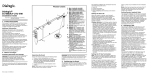
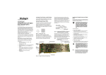
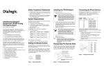
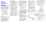
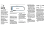
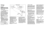
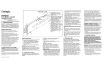
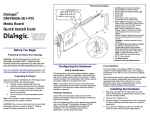
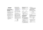
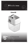
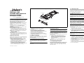
Physical Layout
Dialogic® DSI
SS7MDL440Q Network
Interface Board
Installation Guide
1. Product Description
The Dialogic® DSI SS7MDL440Q Network Interface
Board (“DSI SS7MDL440Q board” or “board”) is a
high performance, low profile, PCI Express form
factor SS7 signaling board designed for use in
telecommunications environments.
The board supports configurations of up to 124 SS7
signaling links, 4 framed HSL links, or 4 ATM cell
streams.
The DSI SS7MDL440Q board includes the following
components, shown in the Physical Layout
illustration:
End Bracket: Bracket supplied for both low profile
and full height installation.
Port 0 to Port 3: Four primary rate
telecommunication interface connectors that are
run-time configurable to operate as T1, E1, or J1
ports, with selectable line code and frame format.
LEDs: Each port is provided with a Green/Red bicolor LED to indicate status:
■ Green = Line Ok
■ Red = Line Alarm
Bus Interface: The DSI SS7MDL440Q board is a 4
lane PCI Express physical form factor with a single
lane connected, which can be installed in 4, 8, or
16 lane PCI Express slots.
Additional Information
Additional information about each DSI SS7MDL440Q
board and the specifications to which it conforms is
available in the following documents:
■ The Regulatory Notices document, packed with
each DSI SS7MDL440Q board, contains safety
warnings and international and national
requirements for proper installation and operation
of telecommunications equipment.
■ Dialogic® DSI SS7MD Network Interface Board
Programmer's Manual, available at http://
www.dialogic.com/support/helpweb/signaling,
provides information about the software used with
each DSI SS7MDL440Q board, including
Part number: 64-0360-01
Bus Interface
Port 0
Port 1
Port 2
Port 3
For restrictions, refer to the DSI SS7MD Network
Interface Board Programmer's Manual and the host
computer documentation. Ensure that the creepage
and clearance requirements are met, as specified in
the Regulatory Notices document.
5. Installing the Board
Bracket Retaining Screw
Copyright © 2009 Dialogic Corporation.
All rights reserved.
4. Choosing a Slot
CAUTION: These procedures assume familiarity
with the general terminology associated with
electronic equipment and with the safety practices
and regulatory compliance required for using and
modifying electronic equipment. These procedures
should be performed only by qualified technical
personnel.
Low Profile Bracket
WARNING! Unplug the equipment before
performing the procedures described here.
Failure to disconnect the power before you
open the chassis can result in personal injury.
Ensure that the system is disconnected from its
power source and from all telecommunications
links, networks, or modem lines whenever the
chassis cover is removed. Do not operate the
system with the cover removed.
Port Status LEDs
Full Height Bracket
(Optional)
CAUTION: Observe proper anti-static precautions at
all times while handling and installing the board.
■
■
■
configuration parameters and command
descriptions.
The product data sheet, available at
http://www.dialogic.com/products/list.asp,
provides a functional description as well as
information about applications and configurations,
features, and technical specifications.
The latest software, available at http://
www.dialogic.com/support/helpweb/signaling.
PCI Express Base Specification Rev 1.0a, available
at http://www.pcisig.com.
2. Before You Begin
Familiarize yourself with the safety aspects and other
essential or national requirements in the Regulatory
Notices document.
Protecting the Board from Damage
CAUTION: All computer boards are sensitive to
electrostatic discharge (“ESD”). Handle all staticsensitive boards and components at a static-safe
work area, and observe anti-static precautions at all
times.
If you are not familiar with ESD safety precautions,
visit http://www.dialogic.com/support/hwinstall to
learn more.
Unpacking the Board
CAUTION: Do not remove the board from the antistatic packaging until you are ready to install it.
Observe proper anti-static precautions at all times.
Inspect the packaging for any signs of damage that
may have occurred during transit. In the event of
damage or missing items notify both the carrier and
the supplier immediately.
Unpack the DSI SS7MDL440Q board according to the
following steps:
1. Prepare a static-safeguarded work area.
2. Carefully remove the board from the shipping
carton and anti-static packaging. Handle the
board by the edges and avoid touching the
board’s components.
3. Lay the board on the static-dissipative work
surface.
Note: Place board in static-shielding bag when
carrying board from station to station.
3. Configuring the Board
Software configurable parameters must be set, as
described in the DSI SS7MD Network Interface Board
Programmer's Manual. These include parameters
relating to T1/E1/J1 ports, pulse shape, line code,
and frame format.
To install the DSI SS7MDL440Q board, perform the
following steps:
1. Turn off the computer and disconnect the power
cable and network connections.
2. Remove the cover from the computer.
3. Select an empty, PCI Express slot and remove the
blanking plate (if fitted) by removing the retaining
screw at the top of the plate. Keep the blanking
plate for future use.
CAUTION: To prevent damage to the board or
computer, care should be taken to ensure correct
alignment of the connector and board guide before
final insertion.
4. The end bracket on the board may need to be
changed between either low profile or full height
to match the selected host PCI Express slot.
Instructions on how to do this are provided in
Section 6, Changing the End Bracket.
5. Using the board guides in the computer, align the
board with the slot and press the board firmly
until fully seated.
6. Secure the board using the retaining screw at the
top of the end bracket.
7. Replace the cover on the computer and reconnect
the power cable and network connections.
8. Turn on the computer.
6. Changing the End Bracket
Change the end bracket as follows:
1. Remove the retaining screw from the top of the
board and retain for re-use.
2. Rotate the top of the end bracket away from the
board to clear the underside of the connector.
3. Slide the end bracket down until the retaining
hook releases the connector.
4. Follow the reverse procedure to fit the new end
bracket.
5. Replace the retaining screw.
7. Connecting to External Equipment
Connecting T1, E1, or J1 Cables
Connect T1, E1, or J1 cables to the Port 0 to Port 3
connectors on the end bracket. Connector pinouts for
the Port 0 to Port 3 connectors are shown in the
following figure.
Note: Cables must be twisted pair.
Port 0 to Port 3 Connector Pinouts
Pin 1
Pin
1
2
3
4
5
6
7
8
Function
RCV_RING
RCV_TIP
N/C
XMIT_RING
XMIT_TIP
N/C
N/C
N/C
8. After Installing the Board
After installing the DSI SS7MDL440Q , refer to the
DSI SS7MD Network Interface Board Programmer's
Manual for software installation and configuration
instructions. Ensure that the configuration is
compliant with all local requirements.
Refer to the DSI SS7MD Network Interface Board
Programmer's Manual for software licensing
instructions.
9. Removing the Board
CAUTION: Components may be hot.
When the board is removed from a system, the board
may contain hot components. To avoid risk of burns,
the board should only be handled by the end bracket
until the components have had time to cool.
Removal of the board is essentially the reverse of the
installation procedure described in Section 5,
Installing the Board, as summarized in Step 1
through Step 6 below:
1. Observe anti-static precautions.
2. Disconnect the telephony cables.
3. Remove the computer’s power cord.
4. Remove the computer’s cover.
5. Remove and set aside the board’s retaining screw.
6. Remove the board and place it in static protective
packaging.
10.Warranty and Return Information
Warranty Period
For specific warranty information for this board, refer
to the Warranty section of the Products page, located
at this URL: http://www.dialogic.com/warranties/.
Contacting Technical Support
Dialogic provides technical support for its products
through a network of value added distributors who
are trained to answer technical questions on installing
and configuring Dialogic® products. If you are unsure
how to contact your support channel, please call
Dialogic in the United States at 973-967-6600 (9am5pm EST) and we will assist in obtaining the
appropriate support channel.
Outside the United States please refer to http://
www.dialogic.com/support/contact to obtain local
contact information. Dialogic also provides direct
support via Dialogic® Pro™ Services agreements. For
more details of direct support from Dialogic please
refer to: http://www.dialogic.com/support/
DialogicPro.
Returning a Product
To return a board for warranty repair or any other
returns, please refer to the following: http://
www.dialogic.com/support/hwfaults.
11.Sales Assistance
If you have a sales question, please contact your
local Sales Representative or the Regional Sales
Office for your area. Address, telephone and fax
numbers, are available at the Dialogic website
located at: http://www.dialogic.com/contact.htm.
To purchase Dialogic® products, please refer to the
following website to locate the appropriate supplier:
http://www.dialogic.com/purchase.htm.
Copyright © 2009 Dialogic Corporation. All Rights Reserved.
You may not reproduce this document in whole or in part
without permission in writing from Dialogic Corporation at the
address provided below.
All contents of this document are furnished for
informational use only and are subject to change
without notice and do not represent a commitment
on the part of Dialogic Corporation or its subsidiaries
(“Dialogic”). Reasonable effort is made to ensure the
accuracy of the information contained in the
document. However, Dialogic does not warrant the
accuracy of this information and cannot accept
responsibility for errors, inaccuracies or omissions
that may be contained in this document.
INFORMATION IN THIS DOCUMENT IS PROVIDED IN
CONNECTION WITH DIALOGIC® PRODUCTS. NO
LICENSE, EXPRESS OR IMPLIED, BY ESTOPPEL OR
OTHERWISE, TO ANY INTELLECTUAL PROPERTY
RIGHTS IS GRANTED BY THIS DOCUMENT. EXCEPT
AS PROVIDED IN A SIGNED AGREEMENT BETWEEN
YOU AND DIALOGIC, DIALOGIC ASSUMES NO
LIABILITY WHATSOEVER, AND DIALOGIC DISCLAIMS
ANY EXPRESS OR IMPLIED WARRANTY, RELATING TO
SALE AND/OR USE OF DIALOGIC PRODUCTS
INCLUDING LIABILITY OR WARRANTIES RELATING
TO FITNESS FOR A PARTICULAR PURPOSE,
MERCHANTABILITY, OR INFRINGEMENT OF ANY
INTELLECTUAL PROPERTY RIGHT OF A THIRD PARTY.
Dialogic products are not intended for use in medical,
life saving, life sustaining, critical control or safety
systems, or in nuclear facility applications.
Due to differing national regulations and approval
requirements, certain Dialogic products may be
suitable for use only in specific countries, and thus
may not function properly in other countries. You are
responsible for ensuring that your use of such
products occurs only in the countries where such use
is suitable. For information on specific products,
contact Dialogic Corporation at the address indicated
below or on the web at www.dialogic.com.
It is possible that the use or implementation of any
one of the concepts, applications, or ideas described
in this document, in marketing collateral produced by
or on web pages maintained by Dialogic may infringe
one or more patents or other intellectual property
rights owned by third parties. Dialogic does not
provide any intellectual property licenses with the
sale of Dialogic products other than a license to use
such product in accordance with intellectual property
owned or validly licensed by Dialogic and no such
licenses are provided except pursuant to a signed
agreement with Dialogic. More detailed information
about such intellectual property is available from
Dialogic’s legal department at 9800 Cavendish Blvd.,
5th Floor, Montreal, Quebec, Canada H4M 2V9.
Dialogic encourages all users of its products to
procure all necessary intellectual property
licenses required to implement any concepts or
applications and does not condone or
encourage any intellectual property
infringement and disclaims any responsibility
related thereto. These intellectual property
licenses may differ from country to country and
it is the responsibility of those who develop the
concepts or applications to be aware of and
comply with different national license
requirements.
Dialogic, Dialogic Pro, Brooktrout, Diva, Cantata,
SnowShore, Eicon, Eicon Networks, NMS
Communications, NMS (stylized), Eiconcard,
SIPcontrol, Diva ISDN, TruFax, Exnet, EXS, SwitchKit,
N20, Making Innovation Thrive, Connecting to
Growth, Video is the New Voice, Fusion, Vision,
PacketMedia, NaturalAccess, NaturalCallControl,
NaturalConference, NaturalFax and Shiva, among
others as well as related logos, are either registered
trademarks or trademarks of Dialogic Corporation or
its subsidiaries. Dialogic's trademarks may be used
publicly only with permission from Dialogic. Such
permission may only be granted by Dialogic’s legal
department at 9800 Cavendish Blvd., 5th Floor,
Montreal, Quebec, Canada H4M 2V9. Any authorized
use of Dialogic's trademarks will be subject to full
respect of the trademark guidelines published by
Dialogic from time to time and any use of Dialogic’s
trademarks requires proper acknowledgement.
The names of actual companies and products
mentioned herein are the trademarks of their
respective owners.