1
Dialogic® 4000 Media Gateway Series
Quickstart Guide
February 2011
64-1169-01
www.dialogic.com
Dialogic® 4000 Media Gateway Series Quickstart Guide
Copyright and Legal Notice
Copyright © 2011 Dialogic Inc. All Rights Reserved. You may not reproduce this document in whole or in part without permission
in writing from Dialogic Inc. at the address provided below.
All contents of this document are furnished for informational use only and are subject to change without notice and do not
represent a commitment on the part of Dialogic Inc. and its affiliates or subsidiaries ("Dialogic"). Reasonable effort is made
to ensure the accuracy of the information contained in the document. However, Dialogic does not warrant the accuracy of this
information and cannot accept responsibility for errors, inaccuracies or omissions that may be contained in this document.
INFORMATION IN THIS DOCUMENT IS PROVIDED IN CONNECTION WITH DIALOGIC® PRODUCTS. NO LICENSE, EXPRESS OR
IMPLIED, BY ESTOPPEL OR OTHERWISE, TO ANY INTELLECTUAL PROPERTY RIGHTS IS GRANTED BY THIS DOCUMENT. EXCEPT
AS PROVIDED IN A SIGNED AGREEMENT BETWEEN YOU AND DIALOGIC, DIALOGIC ASSUMES NO LIABILITY WHATSOEVER,
AND DIALOGIC DISCLAIMS ANY EXPRESS OR IMPLIED WARRANTY, RELATING TO SALE AND/OR USE OF DIALOGIC PRODUCTS
INCLUDING LIABILITY OR WARRANTIES RELATING TO FITNESS FOR A PARTICULAR PURPOSE, MERCHANTABILITY, OR
INFRINGEMENT OF ANY INTELLECTUAL PROPERTY RIGHT OF A THIRD PARTY.
Dialogic products are not intended for use in medical, life saving, life sustaining, critical control or safety systems, or in nuclear
facility applications.
Due to differing national regulations and approval requirements, certain Dialogic products may be suitable for use only in
specific countries, and thus may not function properly in other countries. You are responsible for ensuring that your use of
such products occurs only in the countries where such use is suitable. For information on specific products, contact Dialogic
Inc. at the address indicated below or on the web at www.dialogic.com.
It is possible that the use or implementation of any one of the concepts, applications, or ideas described in this document, in
marketing collateral produced by or on web pages maintained by Dialogic may infringe one or more patents or other intellectual
property rights owned by third parties. Dialogic does not provide any intellectual property licenses with the sale of Dialogic
products other than a license to use such product in accordance with intellectual property owned or validly licensed by Dialogic
and no such licenses are provided except pursuant to a signed agreement with Dialogic. More detailed information about such
intellectual property is available from Dialogic's legal department at 926 Rock Avenue, San Jose, California 95131 USA. Dialogic
encourages all users of its products to procure all necessary intellectual property licenses required to implement any concepts
or applications and does not condone or encourage any intellectual property infringement and disclaims any responsibility
related thereto. These intellectual property licenses may differ from country to country and it is the responsibility of those
who develop the concepts or applications to be aware of and comply with different national license requirements.
Dialogic, Dialogic Pro, Dialogic Blue, Veraz, Brooktrout, Diva, Diva ISDN, Making Innovation Thrive, Video is the New Voice,
Diastar, Cantata, TruFax, SwitchKit, SnowShore, Eicon, Eicon Networks, NMS Communications, NMS (stylized), Eiconcard,
SIPcontrol, TrustedVideo, Exnet, EXS, Connecting to Growth, Fusion, Vision, PowerMedia, PacketMedia, BorderNet, inCloud9,
I-Gate, Hi-Gate, NaturalAccess, NaturalCallControl, NaturalConference, NaturalFax and Shiva, among others as well as related
logos, are either registered trademarks or trademarks of Dialogic Inc. and its affiliates or subsidiaries. Dialogic's trademarks
may be used publicly only with permission from Dialogic. Such permission may only be granted by Dialogic's legal department
at 926 Rock Avenue, San Jose, California 95131 USA. Any authorized use of Dialogic's trademarks will be subject to full respect
of the trademark guidelines published by Dialogic from time to time and any use of Dialogic's trademarks requires proper
acknowledgement.
Microsoft is a registered trademarks or trademark of Microsoft Corporation in the United States and/or other countries. Other
names of actual companies and products mentioned herein are the trademarks of their respective owners.
Page 2
Overview
Overview
This document provides a high-level overview of how to connect power and network cabling for a Dialogic® 4000
Media Gateway Series. The term "DMG4000 Gateways" is used herein to refer collectively to the Dialogic® 4000
Media Gateway Series, and the term "DMG4000 Gateway" is used herein to refer to a gateway in the Dialogic®
4000 Media Gateway Series.
DMG4000 Gateways use a Dell PowerEdge R310 as a server system. For more information about this hardware,
see the Dell web site at http://www.dell.com.
To view a copy of the Software License Agreement for the DMG4000 Gateway, see:
http://www.dialogic.com/manuals/dmg30004000/default.htm
Available Dialogic® 4000 Media Gateway Series Versions
The following DMG4000 Gateways are available:
Version
Dialogic® Diva® Media
Boards installed
Channels Voice Channels T.38 Fax Channels Dialogic®
Diva® SIPcontrolTM
Software
DMG4008BRISBA
Diva 4BRI-8 PCIe
8
8
8
DMG4008LSSBA
Diva Analog-8 PCIe
8
8
8
DMG4030DTISBA
Diva V-1PRI PCIe HS
30
30
30
*
DMG4060DTISBA
Diva V-2PRI PCIe HS
60
12-60
DMG4060DTIV34SBA
Diva V-2PRI PCIe HS
60
60
60
60
*
DMG4120DTISBA
Diva V-4PRI PCIe HS
120
12-120
120
DMG4120DTIV34SBA
2 X Diva V-2PRI PCIe HS
120
120
120
*These
DMG4000 Gateways are shipped with a fax license for 12 channels. If you need more channels, you are
required to purchase a license. For information about licenses, see the Dialogic® 4000 Media Gateway Series
Reference Guide at http://www.dialogic.com/manuals/dmg30004000/default.htm.
Note: For Service update 4 (SU4), all DMG4000 Gateway versions support G.711 pass through fax only. It is
planned that T.38 capabilities will be added back in the next service update.
Page 3
Dialogic® 4000 Media Gateway Series Quickstart Guide
General Safety Instructions
For general safety instructions, refer to the the Dell Product Information Guide, which is included with the
DMG4000 Gateway kit, and to the following:
WARNING
• Never touch non-insulated telephone wires or terminals unless the telephone line
has been disconnected at the network interface.
• Use caution when installing or modifying telephone lines.
• Telephone companies report that electrical surges, typically lightning transients,
are very destructive to customer terminal equipment connected to AC power
sources. The use of a surge arrestor on the AC line is recommended.
Warning! Do not attempt to modify or use the supplied AC power cord if it is not
the exact type required.
Avertissement! Ne pas utiliser ni modifier le câble d'alimentation secteur fourni,
s'il ne correspond pas exactement au type requis.
Warnung! Versuchen Sie nicht, das mitgelieferte Netzkabel zu verändern oder zu
verwenden, wenn es sich nicht um genau den erforderlichen Typ handelt.
Avvertenza! Non modificare o utilizzare il cavo di alimentazione in c.a. fornito dal
produttore, se non corrisponde esattamente al tipo richiesto.
¡Advertencia! No intente modificar ni usar el cable de alimentación de corriente
alterna, si no corresponde exactamente con el tipo requerido.
• In some cases, the power cord supplied with this system may not be compatible
with the AC wall outlet in your region. If this is true, you must obtain a suitable
power cord that meets the following criteria:
• The cord must be rated for use at the AC voltage available, with a current rating
that is at least 125% of the current rating of the product (for current rating
information, refer to the regulatory label affixed to the product).
• The AC plug end must be terminated in a grounding-type male plug designed
for use in your region. The plug ends must be labeled or marked to indicate
they have been certified by an agency acceptable in your region.
• The power service must be connected through a properly grounded outlet.
• The connector at the product end must be an IEC 320, sheet C13, female
connector (or the equivalent EN 60 320 connector).
• The cord must be less than 14.8 feet (4.5 meters) long and, for use in Europe,
be created with <HAR> (harmonized) or VDE certified cordage.
• If power needs to be removed from this product, you must disconnect the
power cord; therefore, the socket-outlet shall be installed near the equipment
and shall be easily accessible.
INFORMATION
• To help protect your gateway from transient increases and decreases in electrical
power, use a surge suppressor, line conditioner, or uninterruptible power supply
(UPS).
• Keep your gateway away from radiators and heat sources. Also, do not block
cooling vents.
Dialogic® Diva® PRI Media Boards
Cables for Interface ports used for the Dialogic® 4000 Media Gateway Series shall
be shielded.
Page 4
Front Panel
Front Panel
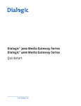
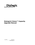
The following illustration shows the front panel of a DMG4000 Gateway:
Number
Description
1
Power-on indicator
Power button
2
NMI button
3
Video connector
4
Hard-drive activity indicator
5
LCD panel
6
System identification button
7
System status indicator
8
Two USB connectors
9
Two hard drives
10
System identification
Page 5
Dialogic® 4000 Media Gateway Series Quickstart Guide
Back Panel
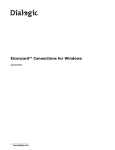
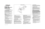
The following illustration shows the back panel of a DMG4000 Gateway
Number
Description
1
Slot for the first Dialogic® Diva® Media Board
2
Slot for the second Dialogic® Diva® Media Board
3
Two power supplies
4
Serial connector
5
Video connector
6
Two USB connectors
7
Two Ethernet connectors
8
Active ID CMA connector
9
System status indicator
10
System identification button
Installation
1. Take the DMG4000 Gateway, and identify its connectors. For information, see Front Panel on page 3, and
Back Panel, above.
2. Connect the mouse and keyboard to the USB connectors.
3. Connect one end of the Ethernet cable to the Ethernet connector 1 and the other end to the corporate
Ethernet. For fault tolerance and load balancing, also connect a cable to Ethernet connector 2 the same way.
See the above graphic above for the numbering of the connectors.
4. Connect the monitor to the video connector.
5. Connect your PRI, BRI, or analog telephone cables to the Diva Media Board in slot 1. Plug one end of the
cables into the ports of the Diva Media Board. Plug the other end into the ports of the PBX. The ports of the
Diva Media Board in slot 1 are numbered from 1 to 4 from the left to the right. The port numbers may be
important during the software configuration.
If the DMG4000 Gateway contains a second Diva Media Board in slot 2, connect this board as described
above. The ports of the Diva Media Board in slot 2 are numbered from 4 to 1 from the left to the right.
Note: The ports on the analog Diva Media Board included with the DMG4008LSSBA are numbered as follows
from left to right: 1/2 3/4 5/6 7/8.
6. Plug one end of the first power cord into one of the power supplies. Connect the other end to power source.
Connect the second power cord the same way. It is recommended to connect both power supplies for proper
functioning of the DMG4000 Gateway.
7. Switch on the DMG4000 Gateway.
Page 6
LCD Panel
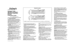
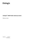
LCD Panel
The following LCD panel is integrated in the front panel of the DMG4000 Gateway:
Number
Button
Description
1
Left
Moves the cursor back in one-step increments.
2
Select
Selects the menu item highlighted by the cursor.
3
Right
Moves the cursor forward in one-step increments.
During message scrolling:
• Press once to increase scrolling speed.
• Press again to stop.
• Press again to return to default scrolling.
• Press again to repeat the cycle.
4
System ID
Turns the system ID mode on (LCD panel flashes blue) and off.
Press quickly to toggle the system ID on and off. If the system
hangs during POST, press and hold the system ID button for
more than five seconds to enter BIOS Progress mode.
The LCD panel provides messages that signify whether the system is operating correctly or if it needs attention:
• A blue light indicates a normal operation condition.
• An amber light indicates an error condition.
If there is an error, the LCD panel displays a message that consists of a status code followed by descriptive text.
The message refers to events recorded in the System Event Log (SEL). For information about LED panel status
messages and their corresponding corrective actions, see the documentation for the Dell PowerEdge R310 on
the Dell website (http://www.dell.com).
Page 7
Dialogic® 4000 Media Gateway Series Quickstart Guide
Hard-Drive Status Indicators
The following illustration shows the location of the hard-drive indicators:
Number
Description
1
Drive status indicator, which can be green or amber
2
Drive activity indicator, which is green when the drive is
accessed
3
Button to unlock the hard drive, when you want to replace it
in case of failure
The drive status indicator blinks as follows to indicate drive conditions:
Blink Pattern (RAID Only)
Condition
Blinks green two times per second
Identify drive/preparing for removal.
Off
Drive ready for insertion or removal.
The drive status indicator will remain off until all hard drives
are initialized after system power is applied. Drives are not
ready for insertion or removal during this time.
Blinks green, amber, and off
Drive predicted failure.
Blinks amber four times per second
Drive failed.
Blinks green slowly
Drive rebuilding.
Steady green
Drive online.
Blinks green three seconds, amber three Rebuild aborted.
seconds, and off six seconds
Page 8
Network Interface Controller (NIC Indicator) Codes
Network Interface Controller (NIC Indicator) Codes
The following illustration shows the location of the NIC indicators:
Number
Description
1
Link indicator
2
Activity indicator
The NIC indicators light up as follows to show NIC conditions:
Indicator
Condition
Link and activity indicators are off.
The NIC is not connected to the network.
Link indicator is green.
The NIC is connected to a valid network link at 1000 Mbps.
Link indicator is amber.
The NIC is connected to a valid network link at 10/100 Mbps.
Activity indicator is green and blinking.
Network data is being sent or received.
Power Indicator Codes
Each power supply on the DMG4000 Gateways has an indicator that shows whether power is present or whether
a power fault has occurred. The following illustration shows where the power supply status indicator is located
(marked by a 1):
Page 9
Dialogic® 4000 Media Gateway Series Quickstart Guide
The power supply status indicator lights up as follows to show power supply conditions:
Indicator
Condition
Not lit
AC power is not connected.
Green
In standby mode, indicates that a valid AC source is connected
to the power supply, and that the power supply is operational.
When the system is on, it also indicates that the power supply
is providing DC power to the system.
Amber
Indicates a problem with the power supply
Alternating green and amber
When hot-adding a power supply, this indicates that the power
supply is mismatched with the other power supply (a high
output power supply and an Energy Smart power supply are
installed in the same system). Replace the power supply that
has the flashing indicator with a power supply that matches
the capacity of the other installed power supply.
Technical Specifications
Environmental requirement:
Operating temperature range: 10 degrees Celsius to 35 degrees Celsius
Dialogic® 4000 Media Gateways
CPU
Intel Xeon 3430 series processor
Memory
8GB 1333MHz
Dimensions in mm
Height:
42.4
Width:
434
Length:
610
External interface
4 USB (2.0) ports
VGA port
RS232 Serial port
2x Gigabit-Ethernet ports
Power supply
2 power supplies; each with:
100-240 Vac
50/60 Hz
4/2 A
More Information
For more information about DMG4000 Gateways, see the following manuals, which are available at
http://www.dialogic.com/manuals/dmg30004000/default.htm.
For...
See the...
Information about configuring a DMG4000 Gateway
Dialogic® 4000 Media Gateway Series Reference Guide
Information about deploying a DMG4000 Gateway as a Deploying a Dialogic® 4000 Media Gateway as a Survivable
survivable branch appliance with Microsoft® Lync™
Branch Appliance for Microsoft® Lync™ Server 2010
Server 2010
Detailed information about Dialogic® Diva® System
Release software
Dialogic® Diva® System Release 9.5WIN Reference Guide
Detailed information about Dialogic® Diva® SIPcontrol™ Dialogic® 4000 Media Gateway Series Reference Guide or
software
the Dialogic® Diva® SIPcontrol™ Software 2.5 Reference
Guide
Page 10