1
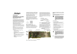
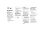
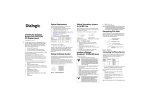
Setting the Module Number (SW1) Installing the Dialogic® Brooktrout® TR1034 Digital / Ethernet Fax Board (Single Span) Part Number: 931-101-05 The Dialogic® Brooktrout® TR1034 Digital/Ethernet combination PCI fax boards (“TR1034” or “TR1034 Fax Board(s)”) are full-sized, single slot, PCI bus compatible boards with T1/E1, Ethernet, and H.100 capabilities. The TR1034 delivers 33.6 Kbps (V.34) fax transmission speeds, up to 30 fax channels per fax board, Adaptive Call Progress, Error Correction Mode, MMR fax compression, and an onboard T1/E1 interface (see Figure 6). The Ethernet connector is used for T.38 Fax over IP. The Dialogic® Brooktrout® TR1034 Fax Board has access to off-board resources using the H.100 bus interface. Using a bus adapter (available separately), the H.100 can interoperate with an MVIP or SCbus interface. You must set each TR1034 Fax Board to a unique module number to identify the resources associated with a specific board in a multi-board system. SW1 (Figure 1) is a rotary switch (see location in Figure 4). Use it to set the module number for each TR1034 Fax Board. The available settings are 2 - F (0 and 1 are reserved). Rotary Switch - SW1 Using the H.100 Termination Switch (SW2) On a single TR1034 or on multiple TR1034 Fax Boards installed in the same chassis, leave SW2 in the OFF position. See Figure 4 for its location. Multiple TR1034 Fax Boards in the same system do not require the use of a connecting H.100 cable. If you have a TR1034 and other boards that need to be connected using an H.100 cable (not supplied), you must terminate the H.100 clock signal. Only the boards at each end of the cable must be terminated. All other boards must not be terminated (see Figure 2). Set H.100 switches on these boards to the OFF position. Setting Clock Termination in a Series of Boards Connected by an H.100 Bus Push switch toward board to turn ON. Figure 3 SW2 - H.100 Clock Termination Switch LEDs* H.100 Connector SW2 - H.100 Termination Switch Mounting Bracket SW1 - Rotary Switch Caution: A small amount of static electricity can destroy the sensitive components on your board. To prevent static damage, always connect yourself to ground using a ground strap before touching a circuit board. Handle boards only by the edges or metal mounting brackets and transport boards in an anti-static bag. Set the H.100 switch to the ON position. SW2 (see Figure 3) controls termination for the H.100 clock signals. Set the switch to ON to terminate the H.100 clock on a TR1034 Fax Board (see Figure 4 for the location of the switch on the board). The SW2 LED lights when SW2 is set to the ON position. D23 - Termination Switch Indicator LED You need a separate fax application to use the TR1034 Fax Board. Please contact your application provider for the correct operating system driver, supporting files, and firmware. To install the board: 1. Power off the computer. 2. Remove the computer cover. If the system has a board hold-down bar, remove it as well. 3. Locate an unused PCI expansion slot and remove the blank bracket. The TR1034 Fax Board comes with an extension bracket that allows it to fit snugly into an ISA form-factor chassis. If you have a PCI form-factor chassis, use a Phillips-head screwdriver to remove the extender bracket (see Figure 4). 4. Holding the TR1034 Fax Board at each top corner, insert the board firmly into the PCI slot, sliding the extender into the side of the chassis, if necessary. 5. Screw the board’s mounting bracket securely to the computer's frame. See Figure 4. 6. Attach the connector on the H.100 cable to the connector on the board, if needed. 7. Replace the computer cover. 8. Turn on the computer. The board status LED (see Figure 4) continuously flashes yellow when you turn the computer on. ISA length chassis extension bracket Warning: When installing the board, be sure that the mounting bracket is securely fastened to the chassis and the chassis is plugged into a grounded three prong plug. Improper chassis or bracket grounding can result in harmful or fatal electrical shock as well as component damage. LEDs* Operating/Environmental Specifications This device must be installed in an enclosure that meets the following electrical and mechanical requirements. Power requirements: Base: 4 A at 5 VDC = 20 W Base + Mezzanine: 5 A at 5 VDC = 25 W Temperature: 0°C - 50°C Humidity: 10% - 95% (noncondensing) Cooling: Direct forced-air flow is required. 33 MHz PCI 2.2 Universal card (3.3/5V signaling) Set the H.100 switch to the ON position. Figure 2 Figure 1 Installing the Dialogic® Brooktrout® TR1034 Fax Board T1/E1 Connector A T1/E1 Status LED A Note: * These LEDs are for manufacturing purposes only. Board Status LED Figure 4 Universal PCI Connector Dialogic® Brooktrout® TR1034 Digital/Ethernet PCI Fax Fax Board Dialogic® Brooktrout® fax boards should not be present in the computer during the installation of any operating system. The operating system can misinterpret the board as being some other device, with unpredictable consequences. Recognizing PCI Slots The PCI connectors in the computer chassis usually appear as white slots. The different variations of PCI connectors that can be used with the TR1034 board are shown in Figure 5. The TR1034 Fax Board can be inserted into any of the PCI slots shown in Figure 5. Universal PCI Board Edge Connector Pinouts for the T1/E1 Connector Dialogic® Brooktrout® Fax Board Status LED Serial Number and MAC Address Pins 1, 2, 4, and 5 on the RJ-48C telephone jack provide T1/E1 data paths to and from the board. The connector pins are configured as shown in the table below and in Figure 7. The Board Status LED indicates the overall status of the TR1034 Fax Board: You can find the board serial number (2 letters and 9 digits) and MAC address (00A08A and 6 more digits) on white labels on the back of the board. Board Status LED Indicates Getting Help Dialogic provides technical support for customers who have purchased hardware or software products from Dialogic. If you purchased products from a reseller, please contact that reseller for technical support. Signal Name RJ-48 Pin 3.3V 32-Bit Connector Transmit (TX) Tip 5 Off Board has no power. 5V 32-Bit Connector 3.3V 64-Bit Connector Transmit (TX) Ring 4 Flashing yellow Receive (RX) Tip 2 Board powered up and ready to load firmware. Receive (RX) Ring 1 Steady red Board powered up, but failed tests. Flashing yellow and green Board is downloading firmware. Flashing green Firmware is downloaded and the board is ready for use. 5V 64-Bit Connector Insert the connector into any of these slots. Figure 5 Pin PCI Slots 1 2 3 4 5 6 7 8 Connecting to the Telephone Service An RJ-48C telephone jack on the board mounting bracket (see Figure 6) provides the connection to the T1/E1 service. Figure 7 T1/E1 Connector A T1/E1 Status LED A Ethernet Ethernet Connector Board Status LED BOARD STATUS T1/E1 RJ48C Pinouts Front View of Mounting Bracket The TR1034 Fax Board, when used with a T1/E1 line, is approved as a DSX-1 device and must be connected to the telecommunications network through a PBX or CSU. Warning: Do not connect the Ethernet cable into the T1/E1 connector, or vice versa. It can cause serious damage to the board. The T1/E1 Status LED on the bracket represents the T1/E1 service status as shown: Off The software has not yet initialized the board with the telephony configuration. Green Normal error-free operation; layer 1 is up. Status Indicators Red Red alarm (loss of incoming network signal). Ethernet Status LEDs Yellow Yellow alarm (transmitting alarm – board is failing to synchronize with incoming signal). Green with flashing red Clocking error, bipolar violation, cyclic redundancy error, or other error. Media: 10BASE-T/100BASE-TX Connector: RJ-45 (Pin 1=TD+, Pin 2=TD-, Pin 3=TD+, Pin 6=RD-) Cabling: Category 5 UTP up to 100m (328 feet) Ethernet Status LEDs Indicates Activity (Flashing yellow) Activity on Ethernet. Link (Green) Link is established. If the equipment is causing harm to the telephone network, the telephone company might request that you disconnect the equipment until the problem is resolved. If you experience trouble with the TR1034 Digital/Ethernet board, for repair or warranty information, please use the contact information below. To obtain technical support, please use the website: www.dialogic.com/support Copyright and Legal Notice Indicates The Ethernet interface LEDs are located on the mounting bracket Ethernet connector (see Figure 6). Figure 6 T1/E1 Status LED T1/E1 Status LED Ethernet Activity LED Ethernet Link LED RX Ring RX Tip No connection TX Ring TX Tip No connection No connection No connection Ethernet Specifications T1/E1 -A Indicates This equipment contains no user-serviceable parts and is not intended for repair by unauthorized personnel. Using the TR1034 Fax Board Once you have installed the TR1034 Fax Board, install and configure your fax software application according to instructions included with the software. After you have set up your software to support the TR1034 Fax Board, you can send and receive faxes. Copyright © 2006-2008] Dialogic Corporation. All Rights Reserved. You may not reproduce this document in whole or in part without permission in writing from Dialogic Corporation at the address provided below. All contents of this document are subject to change without notice and do not represent a commitment on the part of Dialogic Corporation or its subsidiaries. Reasonable effort is made to ensure the accuracy of the information contained in the document. However, due to ongoing product improvements and revisions, Dialogic Corporation and its subsidiaries do not warrant the accuracy of this information and cannot accept responsibility for errors or omissions that may be contained in this document. INFORMATION IN THIS DOCUMENT IS PROVIDED IN CONNECTION WITH DIALOGIC® PRODUCTS. NO LICENSE, EXPRESS OR IMPLIED, BY ESTOPPEL OR OTHERWISE, TO ANY INTELLECTUAL PROPERTY RIGHTS IS GRANTED BY THIS DOCUMENT. EXCEPT AS EXPLICITLY SET FORTH BELOW OR AS PROVIDED IN A SIGNED AGREEMENT BETWEEN YOU AND DIALOGIC, DIALOGIC ASSUMES NO LIABILITY WHATSOEVER, AND DIALOGIC DISCLAIMS ANY EXPRESS OR IMPLIED WARRANTY, RELATING TO SALE AND/OR USE OF DIALOGIC PRODUCTS INCLUDING LIABILITY OR WARRANTIES RELATING TO FITNESS FOR A PARTICULAR PURPOSE, MERCHANTABILITY, OR INFRINGEMENT OF ANY INTELLECTUAL PROPERTY RIGHT OF A THIRD PARTY. Dialogic products are not intended for use in medical, life saving, life sustaining, critical control or safety systems, or in nuclear facility applications. It is possible that the use or implementation of any one of the concepts, applications, or ideas described in this document, in marketing collateral produced by or on web pages maintained by Dialogic Corporation or its subsidiaries may infringe one or more patents or other intellectual property rights owned by third parties. Dialogic Corporation or its subsidiaries do not provide any intellectual property licenses with the sale of Dialogic products other than a license to use such product in accordance with intellectual property owned or validly licensed by Dialogic Corporation or its subsidiaries. More detailed information about such intellectual property is available from Dialogic Corporation's legal department at 9800 Cavendish Blvd., 5th Floor, Montreal, Quebec, Canada H4M 2V9. The software referred to in this document is provided under a Software License Agreement. Refer to the Software License Agreement for complete details governing the use of the software. Dialogic Corporation encourages all users of its products to procure all necessary intellectual property licenses required to implement any concepts or applications and does not condone or encourage any intellectual property infringement and disclaims any responsibility related thereto. These intellectual property licenses may differ from country to country and it is the responsibility of those who develop the concepts or applications to be aware of and comply with different national license requirements. Dialogic, Dialogic Pro, Brooktrout, Cantata, SnowShore, Eicon, Eicon Networks, Eiconcard, Diva, SIPcontrol, Diva ISDN, TruFax, Realblocs, Realcomm 100, NetAccess, Dialogic Corporation © 1998-2008