1
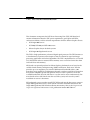
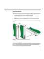
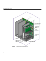
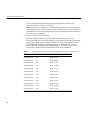
SGI™ Tensor Processing Unit (TPU)
XIO Board Introduction
Document Number 007-4222-002
CONTRIBUTORS
Written by Heidi Racanelli
Illustrated by Carlin Otto, Heidi Racanelli, and Sue Simet
Edited by Mary Geisert and Allison Gosbin
Production by Amy Swenson
Engineering contributions by Larry Mueller, Tom Wieseler, Curt Egner, Dan Bieno
© 1999 - 2000, Silicon Graphics, Inc.— All Rights Reserved
The contents of this document may not be copied or duplicated in any form, in whole
or in part, without the prior written permission of Silicon Graphics, Inc.
RESTRICTED RIGHTS LEGEND
Use, duplication, or disclosure of the technical data contained in this document by
the Government is subject to restrictions as set forth in subdivision (c) (1) (ii) of the
Rights in Technical Data and Computer Software clause at DFARS 52.227-7013
and/or in similar or successor clauses in the FAR, or in the DOD or NASA FAR
Supplement. Unpublished rights reserved under the Copyright Laws of the United
States. Contractor/manufacturer is SGI, 1600 Amphitheatre Pkwy, Mountain View,
CA 94043-1351.
SGI™ Tensor Processing Unit (TPU) XIO Board Introduction
Document Number 007-4222-002
FCC Warning
The equipment described in this guide has been tested and found compliant with the
limits for a Class A digital device, pursuant to Part 15 of the FCC rules. These limits
are designed to provide reasonable protection against harmful interference when the
equipment is operated in a commercial environment. This equipment generates,
uses, and can radiate radio frequency energy and, if not installed and used in
accordance with the instruction manual, may cause harmful interference to radio
communications. Operation of this equipment in a residential area is likely to cause
harmful interference, in which case users will be required to correct the interference
at their own expense.
If this equipment does cause harmful interference to radio or television reception,
which can be determined by turning the equipment off and on, the user is
encouraged to try to correct the interference by one or more of the following
measures:
Reorient or relocate the receiving antenna.
Increase the separation between the equipment and receiver.
Connect the equipment into an outlet on a circuit different from that to which the
receiver is connected.
Consult the dealer or an experienced radio/TV technician for help.
Caution: The user is cautioned that changes or modifications to the equipment not
expressly approved by the party responsible for compliance could void the user’s
authority to operate the equipment.
For additional FCC information, refer to the Interference Handbook 1993 Edition
prepared by the Federal Communications Commission. This booklet can be obtained
by writing to the U.S. Government Printing Office, Superintendent of Documents,
Mail Stop SSOP, Washington, D.C. 20402-9328, ISBN 0-16-041736-8.
International Special Committee on Radio Interference (CISPR)
This equipment has been tested to and is in compliance with the Class A limits per
CISPR publication 22, Limits and Methods of Measurement of Radio Interference
Characteristics of Information Technology Equipment.
Canadian Department of Communications Statement
This digital apparatus does not exceed the Class A limits for radio noise emissions
from digital apparatus as set out in the Radio Interference Regulations of the
Canadian Department of Communications standard NMB-003.
SGI™ Tensor Processing Unit (TPU) XIO Board Introduction
Document Number 007-4222-002
Attention
Cet appareil numérique de la classe A est conforme a la norme NMB-003 du Canada.
JAPAN - VCCI Class A Statement
KOREA - Korea Class A Statement
TAIWAN -CNS 13438 Class A Statement
Manufacturer’s Regulatory Declarations
This peripheral when integrated into the workstation conforms to several national
and international specifications and European directives as listed on the
“Manufacturer’s Declaration of Conformity,” which is included with each computer
system. The CE insignia displayed on each device is an indication of conformity to
the European requirements.
Your peripheral has several governmental and third-party approvals, licenses, and
permits. Do not modify this product in any way that is not expressly approved by
Silicon Graphics, Inc. If you do, you may lose these approvals and your
governmental agency authority to operate this device.
SGI™ Tensor Processing Unit (TPU) XIO Board Introduction
Document Number 007-4222-002
Silicon Graphics is a registered trademark and SGI and the SGI logo are trademarks
of Silicon Graphics, Inc. IRIX and Onyx2 are registered trademarks and Gigachannel
and Origin are trademarks of Silicon Graphics, Inc.
SGI™ Tensor Processing Unit (TPU) XIO Board Introduction
Document Number 007-4222-002
Contents
Contents
vii
List of Figures
ix
TPU XIO Board Introduction 1
Part Verification 2
Maximum Number of TPU Boards 2
Power Requirements 2
Panel Plate and LEDs 3
Software Installation and Configuration
Slot Selection 5
Startup 12
4
vii
List of Figures
Figure 1
Figure 2
Figure 3
Figure 4
Figure 5
Panel Plate and LEDs for the TPU XIO Board 3
I/O Items in the Origin 2000 Deskside Server 6
I/O Items in the Onyx2 Deskside Server 8
XIO Slots in Origin 200 Gigachannel Expansion Cabinet
(Rackmount Rear) 9
I/O Items in Origin 2000 Rackmount, SGI 2400, and SGI 2800
Server Processor Module 11
ix
0. TPU XIO Board Introduction
This document accompanies the SGI Tensor Processing Unit (TPU) XIO board and
contains information about the TPU power requirements, panel plate and LEDs,
software installation, and slot selection requirements for these Silicon Graphics chassis:
•
SGI Origin 2000 servers
•
SGI 2200, SGI 2400, and SGI 2800 servers
•
Silicon Graphics Onyx2 deskside systems
•
SGI Origin 200 Gigachannel servers
The TPU is a high-performance, advanced digital signal processor. The TPU functions as
a shared-memory coprocessor that improves time-to-solution for signal and image
processing applications and related algorithms. The TPU is implemented as a Crosstalk
I/O (XIO) board and uses mastered direct memory access to read and write data from
and to the host node memory.
XIO boards are optional products for Silicon Graphics platforms that are based on the
scalable shared-memory multiprocessing (S2MP) architecture. Each active XIO slot
provides up to 1.6 megabytes per second of bidirectional bandwidth (that is, 800
megabytes or 6.4 gigabits in each direction) through a crossbar switch that is located on
the system's midplane. Specific XIO products may use either a portion or all of this
available bandwidth. All of the XIO slots in a system can be active simultaneously. For
more details on how XIO slots fit into the rest of the system, refer to each system’s
installation or owner’s documents.
SGI authorized service providers install TPU XIO boards into the host server, except in
Origin 200 Gigachannel servers, which contain customer installable XIO boards. For
Origin 200 Gigachannel XIO board installation instructions, refer to the Origin 200 and
Origin 200 Gigachannel Maintenance Guide, publication number 007-3709-xxx.
1
TPU XIO Board Introduction
Part Verification
Open the XT-TPU-ORIGIN-1 box and verify that these components are included:
•
One SGI TPU XIO board in antistatic bag, part number 013-2590-xxx
•
One SGI Tensor Processing Unit (TPU) XIO Board Introduction, part number
007-4222-xxx (this document)
Maximum Number of TPU Boards
Table 1 summarizes the maximum number of TPU XIO boards that can be installed into
the different chassis and systems.
Table 1
Maximum Number of TPU XIO Boards That Can Be Installed
System
Per Node Board Per Chassis
Origin 2000 deskside,
SGI 2200
3
11
Origin 2000 rackmount, 3
SGI 2400, SGI 2800
11 per module with BaseIO installed or
Onyx2 deskside
3
3
Origin 200 Gigachannel 3
3
12 per module
Power Requirements
Table 2 summarizes the power consumption for the TPU XIO board.
Table 2
Power Requirements for TPU XIO Board
Requirements
Average
44 watts of power
Maximum 5 volts at 2.7 amps, and 3.3 volts at 11.0 amps
2
Panel Plate and LEDs
Unlike most XIO boards, the TPU XIO panel plate has no ports. It contains three round
LEDs. During normal operation, these LEDs illuminate green.
•
2.5 PWR: indicates that 2.5 voltage is supplied to the board.
•
3.3 PWR: indicates that 3.3 voltage is supplied to the board.
•
LINK UP LED: indicates that communications have been established with the
system.
If a problem occurs with power or communications to the board, the LEDs illuminate
amber.
3.3 LINK
2.5
PWR PWR UP
LEDs
2.5
PW
R
3.3
PW LIN
R
K
UP
2.5
PWR
LEDs
3.3 LINK
PWR UP
Figure 1
Panel Plate and LEDs for the TPU XIO Board
Troubleshooting Suggestion
If any LED fails to illuminate, ensure that the correct software is installed and configured;
refer to “Software Installation and Configuration” on page 4. If any LED still does not
illuminate, contact your SGI authorized service provider.
3
TPU XIO Board Introduction
Software Installation and Configuration
If your system is currently up and running, save yourself time and extra system reboots
by installing and configuring the correct version of IRIX before the board is installed.
Follow the instructions below:
1.
Verify that IRIX 6.5.5 or greater is installed:
% versions eoe
I eoe
I eoe.sw.base
date IRIX Execution Environment, version...
date IRIX Base Execution Environment
If these IRIX software subsystems are not installed or if the displayed version is
earlier than 6.5.5, reinstall IRIX from the CD (or other source).
2. Verify that the IP27 PROM revision is 6.25 or greater:
% hinv -mv | grep IP27prom
IP27prom in Module 1/Slot n1: Revision 6.25
IP27prom in Module 1/Slot n2: Revision 6.25
3. Become superuser:
% su
Password:
4. Edit the /var/sysgen/system/irix.sm file to change the TPU lines from EXCLUDE to
INCLUDE:
*
* Tensor Processing Unit support.
*
INCLUDE: tpu
INCLUDE: tpuidbg
INCLUDE: tpusim
DRIVER_ADMIN: tpu_
XBAR_CREDITS=3
DRIVER_ADMIN: tpusim_ NDEV=144
5. Enable large page sizes and remove the page lock limit with the following
commands:
# systune percent_totalmem_16m_pages 20
# systune percent_totalmem_256k_pages 20
# systune maxlkmem 0
6. Run the autoconfig command to build a new operating system (kernel) that includes
the new driver:
# autoconfig
4
Slot Selection
Follow the instructions in this section to select an appropriate XIO slot.
•
“Slot Selection Rules for Origin 2000 Deskside and SGI 2200 Servers” on page 5
•
“Slot Selection Rules for Onyx2 Deskside Systems” on page 7
•
“Slot Selection Rules for Origin 200 Gigachannel Servers” on page 9
•
“Slot Selection Rules for Origin 2000 Rackmount, SGI 2400, and SGI 2800 Servers”
on page 9
Slot Selection Rules for Origin 2000 Deskside and SGI 2200 Servers
Each node board accommodates a maximum of 3 TPU cards. In general, if an server has
a node board in slot N1 or N3 with BaseIO in XIO slot 1, then XIO slots 2–6 are available
(shown in Figure 2). If it has a node board in slot N2 or N4, XIO slots 7–12 are available.
If a module has at least two node boards, one in N1 or N3 and one in N2 or N4, then XIO
slots 2–12 are available. (For servers with 2 or more nodes, refer to Table 3 for the
recommended slot order of installation.)
5
TPU XIO Board Introduction
Upper panel plate
containment bar
slot 9
slot 11
slot 1
slot 3
slot 5
slot 7
Midplane
Compression
connector on
midplane
I/O cage
Middle
card guide
Compression
connector on
board
BaseIO
XIO board
Filler panel
t2 4
slo slot t 6 8
sloslot
0
t 1 12
slo s l o t
XIO board
Lower panel plate
containment bar
Rear of Module
Figure 2
6
I/O Items in the Origin 2000 Deskside Server
Slot Selection Rules for Onyx2 Deskside Systems
Each Onyx2 node board accommodates a maximum of 3 TPU cards. The Onyx2 deskside
system has 6 XIO slots. Slots 3, 5, and 6 (shown in Figure 3) are available for TPU XIO
boards. It is recommended that you fill available odd-numbered slots before filling
even-numbered ones, and that you fill lower-numbered slots before higher-numbered
ones. For example, fill slot 3 before filling either slot 5 or slot 6.
Note: Do not use Onyx2 XIO slots 2 or 4 for the XIO TPU card.
7
TPU XIO Board Introduction
Midplane
O)
seI
Ba
(
t1
s l o lot 3 5
s
t
slo
Upper panel plate
containment bar
Compression
connector for
slot 5
Middle
card guide
Lower card
guide
BaseIO
)
Blank panel
ble
usa able)
t
plates for
( no t us
t6
o
t2
slo
slot 2
sl o t 4 ( n
slo
Figure 3
8
I/O Items in the Onyx2 Deskside Server
Lower panel plate
containment bar
Slot Selection Rules for Origin 200 Gigachannel Servers
The Origin 200 Gigachannel expansion cabinet has 5 XIO slots, which are
numbered 11–15. A maximum of 3 of the 5 XIO slots are available for TPU cards; no
restrictions exist on which 3 of the 5 slots you select.
Retaining plate
Figure 4
XIO slots
XIO Slots in Origin 200 Gigachannel Expansion Cabinet (Rackmount Rear)
Slot Selection Rules for Origin 2000 Rackmount, SGI 2400, and SGI 2800 Servers
1.
If you are installing the board into a system of interconnected racks, determine the
rack into which you will install the board.
2. Within the selected rack, determine which module (that is, the upper or the lower)
you are going to work on.
3. Determine which XIO slots in the selected module are usable. Figure 1 illustrates the
XIO slots in a processor module.
Depending on the number of Node boards, the count of usable XIO slots in a
module can be 6 or 12. In modules that require the BaseIO board, XIO slots 2–6 or
2–12 are available.
9
TPU XIO Board Introduction
The server installation instructions provide information that can help you
determine which of the slots are activated.
Note: In general, if a module has a Node board in slot N1 or N3, then XIO slots 1-6
are available. If it has a Node board in slot N2 or N4, XIO slots 7-12 are available. If
a module has at least two Node boards (one in N1 or N3 and one in N2 or N4), then
all 12 XIO slots are available.
4. Select a slot for the TPU XIO board.
This board can be installed in any of the XIO slots–including slots 1 and 2
(illustrated in Figure 5)–that are designed to accommodate the BaseIO and Internal
PCI Adapter options. Refer to Figure 5. When you select a slot for the TPU board,
fill available odd-numbered slots before filling even-numbered slots, and fill
lower-numbered slots before higher-numbered slots. For servers with 2 or more
nodes, refer to Table 3 for the recommended slot order of installation.
Table 3
Installing TPU Boards to Equalize Bandwidth and Control (Two or More Nodes)
Order of Installation Start Loading XIO Slots Node Board that Controls the XIO Slot
10
First XIO Board
IO1
Nodes 1 and 3
Next XIO Board
IO7
Nodes 2 and 4
Next XIO Board
IO4
Nodes 1 and 3
Next XIO Board
IO8
Nodes 2 and 4
Next XIO Board
IO3
Nodes 1 and 3
Next XIO Board
IO9
Nodes 2 and 4
Next XIO Board
IO6
Nodes 1 and 3
Next XIO Board
IO10
Nodes 2 and 4
Next XIO Board
IO5
Nodes 1 and 3
Next XIO Board
IO11
Nodes 2 and 4
Next XIO Board
IO12
Nodes 2 and 4
Final XIO Board
IO2
Nodes 1 and 3
slot 1
slot 3
slot 5
slot 7
slot 9
slot 11
Midplane
Upper panel plate
containment bar
Compression
connector on
midplane
I/O cage
Middle
card guide
Compression
connector on
board
BaseIO
XIO board
Filler panel
t2 4
slo slot t 6 8
sloslot
0
t 1 12
slo s l o t
XIO board
Lower panel plate
containment bar
Rear of Module
Figure 5
I/O Items in Origin 2000 Rackmount, SGI 2400, and SGI 2800 Server Processor
Module
11
TPU XIO Board Introduction
Startup
When the board is installed and connected, follow the instructions in this section to start
operation.
1.
Power on the system. Follow the appropriate power-on instructions for the system's
configuration.
2. Log on.
3. Verify that the three LEDs on the board illuminate green.
If any LED fails to illuminate, ensure that the correct software is installed and
configured; refer to “Software Installation and Configuration” on page 4. If any LED
still does not illuminate, contact your SGI authorized service provider.
4. Verify that the board was located by the operating system during the bootup:
%hinv | grep Tensor
External Tensor Processing
External Tensor Processing
External Tensor Processing
External Tensor Processing
External Tensor Processing
External Tensor Processing
External Tensor Processing
External Tensor Processing
External Tensor Processing
Unit,
Unit,
Unit,
Unit,
Unit,
Unit,
Unit,
Unit,
Unit,
module
module
module
module
module
module
module
module
module
1
1
1
1
1
1
1
1
1
slot
slot
slot
slot
slot
slot
slot
slot
slot
11
8
10
7
9
4
6
5
3
The number after module and slot should correctly identify the chassis and XIO
slot into which you installed the board. There will be other lines in this display;
however, verify the line that corresponds to the board you installed.
Note: Device directories that correspond to the TPUs installed in the system reside
in /hw/tpu. Additionally, the TPU requires the device directory /hw/tpu/any.
12