1
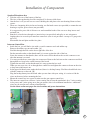
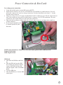
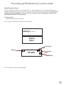
Estate Swing GSM Intercom and
Access Control System
Web Direct Brands, Inc., parent corporation of Estate Swing, warrantees all parts of the
Estate Swing GSM Intercom / Access Control System for a period of 1 year from the
date of purchase. The warranty applies to the original purchaser and is non-transferable.
The warranty applies only to defects in components and workmanship and NOT to damDJHGXHWRFDXVHVEH\RQGWKHFRQWURORI(VWDWH6ZLQJVXFKDVEXWQRWOLPLWHGWRLQFRU
rect voltage, lightning damage, mechanical shock, water damage, fire damage, damage
arising out of abuse and improper application of the equipment, or any acts of nature.
To address a warranty issue please call 1-800-640-4283 between 9-5 EST M-F to receive technical assistance and if deemed needed an RA number from a technician to
send the product or component in for evaluation. All RA must be returned with the RA
number on the outside of the package and with pre-paid postage.
Estate Swing
13100 State Road 54
Odessa, FL 33556
Introduction and Features
Call Button for visitors: The Estate Swing GSM intercom comes with a reception box
that a guest can call the resident from. The call button on the box, when pressed, directs
the system to dial the phone number of the administrator. If there is no answer the system will proceed to call the two manager numbers (if manager numbers exist).
Can hold 1000 authorized numbers: The Estate Swing GSM intercom can be programmed with up to 1000 phone numbers that are authorized users. These users will be
able to call the gate GSM phone number and when their phone number is recognized by
caller id as an authorized user the gate will open. The call is never answered by the
GSM so no minutes are used in this process.
Open the gate with your phone: As an administrator or manager you have many opening options for your gate.
• When you receive a call from a visitor you can open your gate from your phone.
• When entering the property yourself you can open the gate through a phone call to
the gate or an SMS text message to the gate.
• When entering the gate, if you wish to hold the gate open longer than its normal
pause time, for long trailers or trucks for example, you text a 1 time longer delay and
after the one opening it will go back to normal operation automatically.
• If you want to leave the gate open, you can enter party mode and text the gate to stay
open until it is texted again to close it.
Remote programming from phone: The Estate Swing GSM intercom can be programmed by an administrator or manager from their cell phone through a text message.
You can do this from any location. The system will return conformation of successful
programming through a text conformation.
Visual Diagnostic Screen Plug-in: The Estate Swing GSM intercom comes with a diagnostic screen you can plug into the control board to see battery charge, signal strength
and see visual confirmations of programming being performed.
Battery Backup: The Estate Swing GSM intercom comes with a built in battery backup. In the event of a loss of incoming power the system will automatically switch to battery backup. The administrators can also have an option turned on to be notified through
text message of the system switching to battery back up so they can address the lack of
incoming power issue. The back up battery will last approximately 8 hours.
1
Installation of Components
Speaker/Microphone box:
• Take the screw out of the bottom of the box.
• The face of the speaker/mic box lifts straight off, it does not slide down.
• One the face is off you will see two screws holding the mid plate to the rear housing. Remove those
screws.
• There are 4 mounting holes in the rear housing, use flat head screws (not provided) to mount the rear
housing to a pillar, post or fence (not provided).
It is suggested to put a dab of silicone over and around the heads of the screws to keep insects and
moisture out.
• Run the 4 colored wires through to a junction box (not provided) and splice or use wire nuts to
lengthen the wire to reach your intercom control box (wire is not provided—use up to 22 gauge wire
up to 50’)
Reassemble the mid plate and the face plate.
Intercom Control Box:
Inside the box you will find a wire with a coaxial connector and a red rubber cap.
Remove the rubber cap, nut and washer. [A]
Feed this through the hole on the lower right side of the box.
Put the nut and washer on the threads until it is secure against the side of the box.
Screw the antenna on the threads; there will be some visible thread on the coaxial connector even
after the antenna is secured.
• You were provided two water tight wire connectors. Remove the back nut on the connectors and feed
through the two large holes on the bottom of the board.
Tighten the nuts back on the threads until it is snug against the box wall.
When you run your wire, do so through these connectors and tighten the connector down on the wire
to keep water and insects out.
• In the upper left hand corner, under the board, there is a backup battery. Find the red and black wires
with the connector on the end. [B]
Plug the backup battery into the board when you are done with your wiring, it is easier to fish the
wires out however before mounting the box.
• Mount the control box in a secure location near the gate opener control box.
• The intercom control box will have 4 wires coming into it from the speaker/mic box, 2 wires coming
in for power and 2 wires going out to the gate opener. (this is for minimum installation—additional
wires may be used in more advanced installations)
See the chart on the next pages for wire locations and power instructions.
•
[A]
[B]
2
Important: Speaker box splice
Wiring
Speaker/Microphone box to Control Box:
• Black wire to terminal 10
• Red wire to terminal 11
• Green wire to terminal 12
• Yellow wire to terminal 13
• Run between speaker/mic box and control box should not exceed 50’
Splice must be done weatherproof. For
an easy splice use UR telephone wire
connectors.
1. Insert un-stripped wires in
connector.
2. Press down on connector with a
pair of pliers.
Control Box to Gate Opener:
• E-S 1100, E-S 1102, E-SC 1102, E0SL 1200
Terminal 3 of intercom to Terminal 13 of gate opener
Terminal 16 of intercom to Terminal 1 of gate opener
•
•
E-S 1600, E-S 1602, E-SC 1600, E-SC 1602, E-SU2200, E-SU2202, ESL
1800
Terminal 3 of intercom to Terminal COM of gate opener
Terminal 16 of intercom to Terminal OPEN A of gate opener
3. Button will be depressed cutting
into wire and releasing a sealing
gel.
E-S 300, E-S 302, E-S 500, E-S502, E-S 400, E-S 402, E-S 1000D/H
Terminal 3 of intercom to Terminal P1 of gate opener
Terminal 16 of intercom to Terminal V+ of gate opener
3
Power Connection & Sim Card:
Low voltage power connection:
• Verify the On/Off switch is in the OFF position (LEFT)
• In the bottom of the box you will see a red and black wire attached to a round connector. You will
utilize this connector for your low voltage connection. Cut the red and black wire about 2 - 3 inches
from the round connector.
• Using low voltage wire (16-20 gauge stranded direct burial 2 conductor) up to 500 feet connect the red
wire of the connector to the positive and the black to a negative of a 12V DC transformer. The wire
connections can be made using wire nuts inside the control box.
• Plug in the back up battery (upper right side of board, white connector) and plug in the round low
voltage connector.
• Do not turn the On/Off switch
to On until specified by the
directions.
NOTE: Some models have a Black wire with white dashes paired with a solid Black wire:
Dashes: Positive lead
Solid: Negative Lead
SIM Card:
• Slide back the SIM door and lift it
up
• Slide the SIM card into the SIM
door making sure that the clipped
corner of the SIM card lines up
with the clipped corner of the SIM
holder
• Close the SIM door
• Slide the SIM door to lock the SIM
card in place
4
Powering up/Verification of system ready:
Digital Diagnostics Board:
The plug in LED board that comes with the unit is for diagnostic purposes. It is recommended that you
have the installed when you first turn on the system so you can check your system statuses. After you feel
confident with programming or when you close the control box; take the diagnostic display off the
board and store it in a safe dry location.
Turn System on:
Flip the On/Off switch to the right.
•
Once you turn on the system you will see the following
Settings: >>>>
Search
Wait...
Functional
Signal
WT-9002
Power
Battery
Now the system is ready for programming.
5
Initial Setup
Administrator must initially be a cell phone, after programming you can switch the administrator to a land line if you would like that phone to be the first call from the intercom.
Send the following 3 SMS Commands:
FIRST:
*TEL1#1112223333
ALL CAPS MUST BE USED WHEN
SENDING THE UNIT TEXT
MESSAGES.
Replace 1112223333 with the administrator
cell phone.
Wait for the text back from the unit, the text will be:
TEL1=1112223333
__________________________________________________________________________________
SECOND:
*ANY?#1
Wait for the text back from the unit, the text will be:
ANY-ON
__________________________________________________________________________________
THIRD:
*TEL?#1
Wait for the text back from the unit, the text will be:
TEL-ON
If you do not get a text response from the unit try:
• Turning the ON/OFF switch off and then back on, this will reconnect it to the cellular network.
• Checking the diagnostics display and be sure all the indications from the previous
page are on.
• Checking your phones security settings to make sure it shows a caller id when
used.
• Checking your SIM card to be sure it is a GSM format SIM card and that it has
phone and text minutes available and it is activated.
• Do a full unit reset: turn the ON/OFF switch off and unplug the incoming power
and battery. Have a helper hold down the CALL button on the intercom door station. While holding the CALL button reapply power and turn the ON/OFF switch
to on. Wait for the diagnostics display to show OK.
6
Programming Managers
A manager is the second or third phone that will be called if the administrator is unreachable when a person is using the intercom function. A manager can add and remove user numbers and administrator numbers. They can also perform all the Access
Management functions in this manual.
Send the following 2 SMS Commands:
*TEL2#1112223333
Replace 1112223333 with the first manager’s
cell phone.
ALL CAPS MUST BE USED WHEN
SENDING THE UNIT TEXT
MESSAGES.
Wait for the text back from the unit, the text will be:
TEL2=1112223333
__________________________________________________________________________________
*TEL3#1112223333
Replace 1112223333 with the second manager’s
cell phone.
Wait for the text back from the unit, the text will be:
TEL3=1112223333
If you wish to have your cell phone that is currently Administrator be a manager and
the house phone be the Administrator:
1. Do this as your last step after you have reviewed the rest of the manual and you do
not have any more functionality changes you wish to make while you have a cell
phone as manager.
2. Leave the manager spot open that you wish to use as your cell phones position.
3. From the other cell phone that is set up as a manager text the gate the administrator
number using the following command: *TEL1#1112223333
4. Then from that same manager cell phone text the unit the TEL2 or TEL3 position
that you wish to have the cell phone in that was previously administrator. Use the
directions above to text that position.
7
Organizing User Access Phone Numbers:
User access numbers can open the gate by calling the gates phone number and the call id of the unit will
recognize their number and open the gate for them. In order for the system to rapidly sort recognized numbers it stores them in lists 0 through 9. There is the ability to keep up to 99 numbers in each list. It will be
much easier if you organize your phone numbers by list and slot number before programming. The last digit
of the phone number determines its list. Example: if the number ends in 2 then the number has to be in list
2. The slot number (01-99) in list 2 is up to you.
Example of a user list
List 0
none
List 1
Slot 1
Slot 2
684-727-1991
305-700-2261
jack
larry
List 2
Slot 1
734-253-5832
mel
List 3
Slot 1
813-343-0913
karen
List 4
none
List 5
none
List 6
Slot 1
Slot 2
Slot 3
312-348-6546
422-311-9846
422-875-2116
helen
troy
steve
list 7
Slot 1
813-945-8537
tom
List 8
Slot 1
213-253-9748
sue
List 9
none
8
Programming User Access Phone Numbers by SMS:
Users are people that can call the GSM intercom number and make it open the gate. They have no
other abilities.
Example:
To program phone number: 3333333331
Sends SMS command *BOOK#3333333331
Hence 33333333331 is listed in List 1
Returned Message: BOOK<< 3333333331
For phone number: 4444444448
Sends SMS command *BOOK#4444444448
Hence 4444444448 is listed in List 8
Returned Message: BOOK<< 4444444448
Repeat the above for all the numbers you wish to program to open
the gate.
If number is programmed but call is not opening the gate.
Some networks only recognize numbers with a 1 in front of the numbers. Please reset
your system and reprogram all codes including the administrator using a 1 in front of
the numbers being programmed.
9
Programming User Access Phone Numbers by
programming mode:
Programming mode is a function in which users
can be programmed into the white list by their
caller id. When they call the gate the caller id
recognizes the phone number of the guest and
records it for future entry.
Please make sure all the users have their caller id
turned on. If when they call another phone the
caller id displays “private number” their caller id
is turned off.
To enter programming mode:
1. Turn the power off to the unit with the power switch.
2. Using a 12V DC power source (a battery works well). Connect the positive of the power
to terminal 15 and the negative to terminal 11 (4 is also a ground).
3. Turn the power back on to the unit.
You will see the screen to the right. Once it displays
input guest the unit is in programming.
You can now have users call the GSM sim card
number. You only have the allotted amount of time
in the countdown before it automatically exits programming mode.
When the guest calls you will see the guest’s
phone number and the position they are in.
Then it will display OK and reset the timer for
the next guest to call.
If the countdown reaches 0 before the next guest calls turn the power off and then back on to re-enter programming mode.
After you have finished programming turn off the unit and remove the 12V source from terminal 15 and ground. Then turn it
back on for normal operation.
10
Deactivating and Deleting a phone number or group
of numbers:
Deactivating a number
Example:
To deactivate phone number: 6666666667
Send a SMS Command *DEL>#6666666667 to the unit and it will search for number (6666666667) in the list and
deactivate it.
Returned Message:
Delete-OK
____________________________________________________________________________________________
Deactivating all numbers
Send a SMS Command *DELB# to the unit and it will deactivate all user numbers,
Returned Message:
Del-Book
____________________________________________________________________________________________
Restoring deactivated numbers
This will restore any numbers that have been deactivated by the *DEL> or **DELB# command. However if new
numbers were already programmed into the previous slot of the deactivated numbers the deactivated numbers will
not be restorable.
Send a SMS Command *DARE#0 to the unit and it will deactivate all user numbers.
Returned Message:
Recovery-OK
____________________________________________________________________________________________
Permanently deleting all user numbers - non-recoverable
This will delete any user numbers.
Send a SMS Command *DARE#1 to the unit and it will permanently delete all user numbers.
Returned Message:
Delete-OK
11
Phone Call From Gate
When a person presses the call button at the gate the #1 administrator will receive a phone call from the
front gate.
If they do not answer it will roll to the #2 and then to the #3.
______________________________________________________________________________________
In order to open the gate through Relay 1 (this is the primary relay that is normally hooked to the
gate opener) the administrator should press:
*0#
_________________________________________________________________
In order to open a secondary device through Relay 2 (this is the relay that is normally hooked to a pedestrian gate lock or other device) the administrator should press:
*1#
In order to disconnect the call from the gate without opening the gate (this would be if you did not want to
let the person in) the administrator should press:
*4#
This can also be used before hanging up after opening the gate to be sure that the network doesn’t hold the
call from the gate and waste minutes.
12
Administrator and Manager Alt Relay Activation:
Activating relay 2:
There is a second relay which can control another device like a pedestrian gate. You can activate it using
text messaging from an administrator or manager cell phone. (as well as relay 1)
Send either of the following 2 SMS Command:
1) *ECL1#
2) *ECL2#
Returned Message:
ECLK1<OK>
ECLK2<OK>
__________________________________________________________________________________
Party Mode:
You can latch relay 1 or 2 to stay on until commanded to turn off, which can be used to open the gate and
hold it open.
Send either of the following 2 SMS Command:
1) *FRL1#1 – Latch Relay1 to stay ON
2) *FRL2#1 – Latch Relay2 to stay ON
Returned Message:
FRL1<ON>
FRL2<ON>
Send either of the following 2 SMS Command to turn OFF:
1) *FRL1#0 – Switch OFF Relay1
2) *FRL2#0 – Switch OFF Relay2
Returned Message:
FRL1<OFF>
FRL2<OFF>
13
Administrator and Manager Alt Relay Activation:
(cont):
Temporary longer latch:
You can extend the time the gate pauses in the open position by extending the relay latch time for a single
use. This is helpful if you are driving a slow moving or long vehicle. It can be held for up to 65000 seconds.
Example:
Temporary latch Relay 1 for 60 seconds or
Temporary latch Relay 2 for 180 seconds
Simply send either of the 2 SMS command as below:
*RLY1#00060
*RLY2#00180
Example of Returned Message:
RELAY1=00060
RELAY2=00180
14
Administrator Only Special Functions:
Text Reporting to Administrator or Mangers:
It is possible to turn ON/OFF the request of report message when inputs triggered from the unit by sending the following SMS
command to the unit.
Example of sending the below command:
*RERN#100 (Factory Default)
Only Administrator number 1# will receive a report message after setup
Returned Message:
RERN:<100>
*RERN#110
Administrator number 1# and 2# will receive a report message after setup
Returned Message:
RERN:<110>
*RERN#111
All the Administrators will receive a report message after setup
Returned Message:
RERN:<111>
Sending the below command will turn Off this feature:
*RERN#000
__________________________________________________________________________________
Check signal strength:
To check the signal strength (0-31), you would send the following SMS command to the unit.
*CSQ?#
Example of Returned Message:
CSQ=<27>
15
Administrator Only Special Functions (cont):
Text report of gate opening or other event:
You can utilize input terminals 14 and/or 15 to text message the administrators when an event occurs by
using a 12V signal. Some common ways to do this is through a photo eye and a relay or through an output
terminal for a gate lock if it is on a model that puts out 12V DC. Basically you can get notified of any event
or two events as long as the event can be associated to something that generates a temporarily output of 12V
DC (1 to 4 seconds in length). For suggestion on how to accomplish this with your system please call Estate
Swing at 1-800-640-4283.
Notification Message for Input 1:
OUT1<ON>
Notification Message for Input 2:
OUT2<ON>
First, turn on the terminal you wish to use your event device with through SMS text:
Terminal 15 (Input 1)
Terminal 14 (Input 2)
*CTR1#1
*CTR2#1
Returned message: INCTR1=ON
Returned message: INCTR2=ON
Second, activate the TEXT notification for the terminal through SMS text:
Terminal 15 (Input 1)
Terminal 14 (Input 2)
*CTC1#5
*CTC2#5
Returned message: CTC1=<5>
Returned message: CTC2=<5>
__________________________________________________________________________
To turn this function off:
Terminal 15 (Input 1)
*CTR1#0
Terminal 14 (Input 2)
*CTR2#0
Returned message: INCTR1=OFF
Returned message: INCTR2=OFF
16
Administrator Only Special Functions (cont):
Adjusting time ringing to Admin or Manager:
The unit will call the administrator and then the managers if the administrator doesn’t answer. Use this function to change how
long it will try each number before it rolls to the next number. If it reaches voicemail it will not distinguish that from someone
answering the phone.
Example: Change ring time to 15 seconds
Send the following SMS Command
*TETI#15
Example of Returned Message:
TETI:<15>
__________________________________________________________________________________
Turn on or off audible alarm at call box:
When the unit loses main power and is on back up power an alarm will sound at the call box. This function will turn that on or
off.
Turn ON
*ALAC#1
Example of Returned Message:
ALAC-ON
Turn OFF
*ALAC#0
Example of Returned Message:
ALAC-OFF
__________________________________________________________________________________
Changing the time the alarm will sound for:
You can adjust the amount of time the alarm will sound for. The alarm must be active - see above command. Default is 600
seconds.
Example: Sending the following SMS Command
*ALTM#00060 – The alarm will sound for 60 seconds.
Example of Returned Message:
ALTM:<00060>
17
Administrator Only Special Functions (cont):
Power Loss Report:
The unit is able to send alert message to the administrator in the event the main power is out / turned off. When the main power is
restored it can notify the administrator again the main power is on.
When main power OFF
The unit will send a message: ACP-OFF
Note: At the same time, it will send an ALWAYS high pulse out from I/O port. Alarm will sound.
When main power restored
The unit will send a message: ACP-ON
__________________________________________________________________________________
Intercom Volume:
It is possible to adjust the volume (from level 1 to 6) of the intercom by sending the following SMS command. Factory Default:
4
Example: Sending the following SMS Command
*SOUD#5 – Adjust the volume to 5
Example of Returned Message:
SOUND:<5>
__________________________________________________________________________________
Microphone Volume:
It is possible to adjust the volume (from level 1 to 9) of the intercom by sending the following SMS command. Factory Default:
2
Example: Sending the following SMS Command
*MIC0#5 – Adjust the volume to 5
Example of Returned Message:
MIC0:<5>
NOTE: after the C in the above SMS command it is a ZERO, not an O
18
Troubleshooting:
An alarm keeps sounds repeatedly and/or power loss text keeps being sent after switching
unit on:
•
Check to be sure the transformer is a DC transformer. AC power will repeatedly turn the power on and off and
create multiple text messages. AC power may also do irreversible damage to the control board.
Text messages are not being returned:
•
Turn the power off for 5 seconds and then turn back on. This will reconnect your SIM card with the network.
•
Check to see who is an administrator, if you are no longer an administrator you will not receive text
notifications.
•
•
Check to see what # administrators are programmed to receive notification: if any at all. (under special
functions)
Check to make sure your SIM card is a GSM SIM card. Some companies like Sprint Nextel or Track phones
do not use GSM technology with their SIM cards. Our recommended brand is T Mobile (Go Phones work well
and provide a number and a SIM card in one purchase)
I need to reset my entire unit:
•
Turn the unit off. Plug in the digital read out. Press and hold the “Call” button on the gate. Turn the unit back
on and wait approximately 10 seconds while holding the call button on the unit. The unit display will read
“Wait…” and when finished will read “OK”. At this point the unit is reset and your password is returned to
*123456#
I cannot get my SIM card to react to programming:
•
Many SIM cards have an initial 4 digit security PIN code. This must be disabled. This can be done by placing
the card in an unlocked cellular phone and checking to see if the SIM requested a PIN. If there is a PIN
requested, it can be disabled through the phones security settings.
•
Some pay as you go phones have promotions with free minutes. Some of these prmoti0ons lock the SIM card
to the pay as you go phone until the promotional minutes are used.
Everything programmed with the correct text responses - but when I call the system or a
user calls the system it shows NO GUEST
•
Some networks only recognize numbers with a 1 in front of the numbers. Please reset your system and
reprogram all codes including the administrator using a 1 in front of the numbers being programmed.
•
Some networks send both name and phone number with the caller id. Call your service provider and asked to
only send phone number with caller id.
•
Check phone that is calling the intercom and verify that the private setting is off. Private setting is when you
phone does not transmit caller id.
19
Troubleshooting:
I cannot not get my gate opener to activate when I call:
•
View the display when you call:
No Guest indicates caller id not recognized. See above.
No reaction indicates the system is not connecting to the network, turn power off and back
on.
Password on the display indicates the ANY and TEL programming was not done or not
received by the system.
•
Check wiring to gate opener:
The terminals on the gate opener that the wires from intercom relay 1 are leading to - if you
remove the two wires from the intercom, and make momentary contact between them the
gate should open. If it does not you may have the wrong terminals selected on your gate
opener or your gate opener is malfunctioning.
Power your intercom off a separate power supply from your gate opener. Some gate openers
use a shared ground throughout the board for both the accessory power output and the
grounds of the relay inputs. The intercom does as well and this creates a conflict between
the intercom and the gate opener that prevents the relay from triggering the gate opener.
____________________________________________________________________________________________
If you call in for technical support or warranty support: before any control board or
motor will be permitted to be sent in for testing or warranty you will be required to e-mail
digital photos to the technician.
This is done in your best interest to save unnecessary shipping expenses and time lost. Many
times we can come up with solutions to issues by seeing pictures that relay information that is
impossible to relay through a phone conversation.
20
Auxiliary: Land Line Only
NOTE: With land line only usage Administrator functions are not available, just Manager functions.
Programming Managers via phone call:
The manager numbers can be programmed individually or all in one call
using the following [Example numbers are (1111558888), (2222669999), and (3333770000) - substitute
real phone numbers in your programming]. Only
one manager needs to be established to begin using the system.
Diagnostic display read out below
Example:
Once the call has connected… (With a short beep ~ prompt the
manager to enter password, the initial set up password is 123456 by
default)
After enter password… (Another short beep ~ Password Correct)
Press *3# (you should hear a short beep ~ success)
Continue press 1# to add the first manager number (another short
beep ~ success)
Then enter the manager number 1111558888# (you will hear a
short beep ~ the manager number is setup successfully)
Continue...
Press *3# (you should hear a short beep ~ success)
Continue press 2# to add the second manager number (another
short beep ~ success)
Then enter the manager number 2222669999# (you will hear a short beep and the number has been changed
to 2222669999
Continue...
Press *3# (you should hear a short beep ~ success)
Continue press 3# to add the third manager number (another short beep ~ success)
Then enter the manager number 3333770000# (you will hear a short beep and the number has been changed
to 3333770000
If the change has not been successful you will hear 3 beeps and must re-enter again.
21
Auxiliary: Land Line Only (cont)
Programming USER via phone call:
To program [Example number 2222222226 into position 03] in the list:
Press *5# (A short beep ~ success)
Diagnostic display read out below
Guest:
Then you can input the phone number 2222222226# (A short beep ~ success)
And 2222222226 is programmed into list 6
Guest:
2222222226
If the change has not been successful you will hear 3 beeps and must re-enter again.
__________________________________________________________________________________
Changing Passcode via phone call:
The system only allows the 3 manager numbers as authorized user to change the 6 digits password.
To change the password from the factory default 123456 to 654321 (Example) you can just call the unit and when the unit replies,
you can use the following commands using the keypad prompts on your telephone.
Once the call has connected … (With a short beep ~ prompt the administrator to enter password, the initial set up password is
123456 by default)
After enter password… (Another short beep ~Password Correct)
Press *2# (A short beep ~ success)
Then input the current password 123456# (you should hear a short beep ~success)
Continue to enter new password 654321# for 2 times (another short beep if password entered correctly)
If the change has not been successful you will hear 3 beeps and must re-enter again.
__________________________________________________________________________________
Resetting forgotten passcode
To manually reset the unit, you can press and hold on the “Call” button and turn on the unit for 10 seconds. The unit will displays
Wait… and then OK, the unit is reset.
In order for a call into the gate to open the gate without a passcode you will need to set
up a cell phone temporarily as a Administrator and text the unit *ANY?#1
22
Auxiliary: Land Line Only (cont)
Gate Control:
When a person presses the call button at the gate the #1 manager will receive a phone call from the front
gate. If they do not answer it will roll to the #2 and then to the #3.
______________________________________________________________________________________
In order to open the gate through Relay 1 (this is the primary relay that is normally hooked to the
gate opener) the administrator should press:
*0#
_________________________________________________________________
In order to open a secondary device through Relay 2 (this is the relay that is normally hooked to a pedestrian gate lock or other device) the administrator should press:
*1#
In order to disconnect the call from the gate without opening the gate (this would be if you did not want to
let the person in) the administrator should press:
*4#
This can also be used before hanging up after opening the gate to be sure that the network doesn’t hold the
call from the gate and waste minutes.
__________________________________________________________________________________
Temporary longer latch:
You can extend the time the gate pauses in the open position by extending the relay latch time for a single
use. This is helpful if you are driving a slow moving or long vehicle. It can be held for up to 65000 seconds.
Once the call has connected… (With a short beep ~ prompt the administrator to enter password, the initial set up password is
123456 by default)
After enter password… (Another short beep ~ Password Correct)
Press *6# (A short beep ~ success)
Continue press 1# for relay 1 (A short beep ~ success)
Then input value 00030# (A short beep ~ success)
Relay 1 will now latch for 30 seconds and after 30 seconds it will switch off and sends a message back to the administrator informed that Relay 1 has closed.
__________________________________________________________________________________
Display Manager Numbers:
Call the unit while someone is at the gate with the diagnostic screen plugged in. Press *7#.
23