1
06/2009
Overview of alarms
NCK alarms
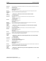
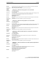
Program Continuation:
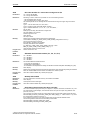
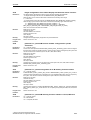
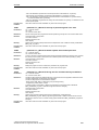
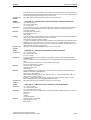
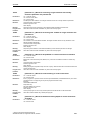
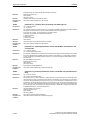
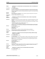
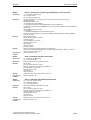
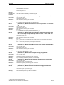
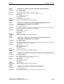
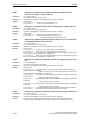
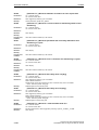
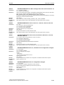
10747
Clear alarm with NC START or RESET key and continue the program.
[Channel %1: ] Block %2 retraction direction not defined for WAB
Parameters:
%1 = Channel number
%2 = Block number, label
Definitions:
In a WAB retraction block with quarter circle or semi-circle (G248 or G348), the end point in the
machining plane was not programmed, and either G143 or G140 without tool radius compensation is
active.
Reaction:
Correction block is reorganized.
Local alarm reaction.
Interface signals are set.
Alarm display.
NC Stop on alarm at block end.
Remedy:
Modify part program. The following changes are possible:
- Indicate end point in the machining plane in the WAB block.
- Activate tool radius compensation (effective for G140 only, not for G143).
- State retraction side explicitly with G141 or G142.
- Perform retraction with a straight line instead of a circle.
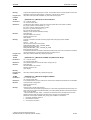
Program Continuation:
Clear alarm with NC START or RESET key and continue the program.
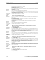
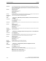
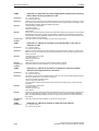
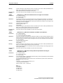
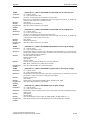
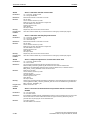
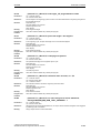
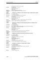
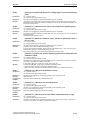
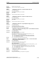
10748
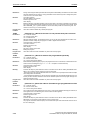
[Channel %1: ] Block %2 illegal retract plane with WAB
Parameters:
%1 = Channel number
%2 = Block number, label
Definitions:
By means of DISRP a position of the retraction plane has been programmed which is not situated
between the safety distance (DISCL) and the starting point (during approach) and/or end point (during
retraction) of the WAB movement.
Reaction:
Correction block is reorganized.
Local alarm reaction.
Interface signals are set.
Alarm display.
NC Stop on alarm at block end.
Remedy:
Modify part program
Program Continuation:
Clear alarm with NC START or RESET key and continue the program.
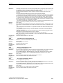
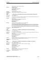
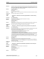
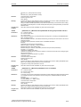
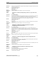
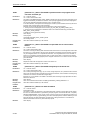
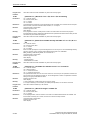
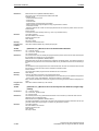
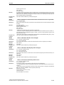
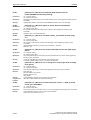
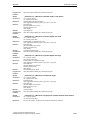
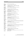
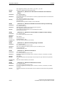
10750
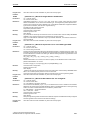
[Channel %1: ] Block %2 tool radius compensation activated without tool
number
Parameters:
%1 = Channel number
%2 = Block number, label
Definitions:
A tool T... must be selected so that the control can make allowance for the associated compensation
values.
A correction data block (D1) containing the correction values (parameter P1 - P25) is automatically
assigned to each tool (T number). Up to 9 correction data blocks can be assigned to a tool by specifying the required data block with the D number (D1 - D9).
The cutter radius compensation (CRC) is allowed for if function G41 or G42 is programmed. The correction values are contained in parameter P6 (geometry value) and P15 (wear value) of the active correction data block Dx.
Reaction:
Correction block is reorganized.
Interpreter stop
Local alarm reaction.
Interface signals are set.
Alarm display.
Remedy:
Before calling the CRC with G41/G42, program a tool number under the address T...
Program Continuation:
Clear alarm with NC START or RESET key and continue the program.
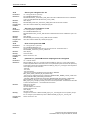
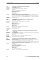
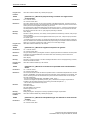
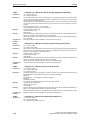
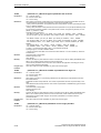
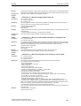
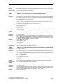
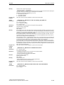
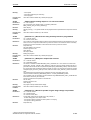
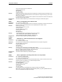
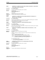
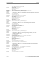
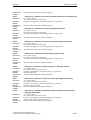
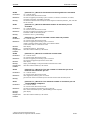
10751
Parameters:
[Channel %1: ] Block %2 danger of collision due to tool radius
compensation
%1 = Channel number
© Siemens AG 2009 All Rights Reserved
SINUMERIK 802D sl, Diagnostics Manual, 06/2009
2-51