1
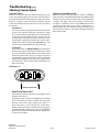
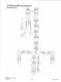
Troubleshooting (cont) Checking Individual Components ConSole MAGneTiC hAll-effeCT SpeeD AnD flow SenSorS CAUTION: Improper connection or voltage could damage the Halleffect sensor. The only way to field test a console is to connect it to a harness on a vehicle with a known working console or install it on an E-POP (Electronic Point of Purchase) display stand. The Hall-effect sensor works similar to a reed switch, but requires power in order to function. Also, this particular type of Hall-effect sensor requires alternating magnetic polarities in order to switch. This means that the north pole of a magnet will “open” the Hall effect and the south pole of a magnet will “close” the Hall effect. hArneSS The harness can be checked using an ohmmeter or continuity tester. The main wiring diagram shows the pin out of all connectors. See page 7 and 9. 25 and 26. eleCTriCAl inTerferenCe Ground pin C (black) and connect clean 12 volts to pin B (white) of the Hall-effect sensor cable. Connect the positive lead (red) of an ohmmeter or continuity tester to pin A (red) and the negative lead (black) of the ohmmeter or continuity tester to pin C of the Hall-effect sensor cable. Erratic operation of the system may be the result of electrical interference from ignition wires or inductive loads (electrical clutch, fan, solenoid, etc). Always try to route wires as far away from suspect areas as possible. If problems occur, you may need to relocate the console and/or wiring harness, or install a noise suppressor. Holding the tip of the sensor up to the north pole of a magnet should result in a very high resistance (infinite), while holding the tip of the sensor up to the south pole of a magnet should result in a very low resistance (around 300 ohms). power Check power source with a test light. If there is no power, trace cable toward battery looking for breaks. Also check any fuses or circuit breakers that supply power to the console. vAnSCo rADAr SpeeD SenSor Carefully check your installation and operating instructions. The following are tips for troubleshooting; ACCeSSory power The speed, flow and run/hold cables all have an accessory power wire. Check for 12 volts between B (usually white) and C (usually black) of these connectors. If power is not present, make sure the accessory power wire is not open or shorted to ground or to another wire. If this wire has a problem, the console may exhibit erratic behavior or not function at all. 1. Disconnect the radar adapter cable from the console harness. 2. Check for 12 VDC between pins B and C of the main harness connector (yellow tie). If not present, console or harness may be defective. rUn/holD hAll-effeCT SenSor CAUTION: Improper connection or voltage could damage the HallEffect sensor. The Halleffect sensor works similar to a reed switch, but requires power in order to function. This particular type of Halleffect sensor “closes” when near the south pole of a magnet and is otherwise “open”. 3. Using a jumper wire (paper clip bent into a “U”), rapidly short together positions A and C of the main harness speed connector (yellow tie) several times. The console should respond with some speed reading. If not, the console or harness may be defective. Ground pin C (black) and connect clean 12 volts to pin B (white) of the Hall-effect sensor cable. Connect the positive lead (red) of an ohmmeter or continuity tester to pin A (red) and the negative lead (black) of the ohmmeter or continuity tester to pin C (black) of the Hall-effect sensor cable. 4. Reconnect the radar adapter cable to the main harness speed connection (yellow tie). 5. Disconnect the radar from the radar adapter cable. 6. Check for 12 VDC between pins 1 and 3 of the radar adapter connector. If it is not present but was present in step 2, the radar adapter cable may be defective. Holding the tip of the sensor up to the south pole of a magnet should result in a very low resistance (around 300 ohms). Taking the sensor away from the magnet should result in a very high resistance (infinite). 7. Using a jumper wire (paper clip bent into a “U”), rapidly short together positions 2 and 3 of the radar connector (round 4-pin) several times. The console should respond with some speed reading. If not but had a reading in step 3, the radar adapter cable may be defective. 8. If system passes all above tests, the radar may be defective. CrustBuster DrillMaster Quick Start Guide 346-001150 30 Pg 21 Revised 11/2010